requires the block size to be smaller. To provide both high throughput and low latency, we have developed an FPGA based data protection system called sAES.
sAES: A High Throughput and Low Latency Secure Cloud Storage with Pipelined DMA Based PCIe Interface Yongzhen Chen, Yi Wang, Yajun Ha
Miguel Rodel Felipe, Shuqin Ren, Khin Mi Mi Aung
ECE Department National University of Singapore Singapore 117576 email: {elecyz, elewyi, elehy}@nus.edu.sg
Storage Institute A*STAR, Singapore email: {Rodel FM, REN Shuqin, Mi Mi AUNG}@dsi.a-star.edu.sg
Abstract—Modern cloud storage requires a high throughput and low latency data protection system, which is usually implemented with an Advanced Encryption Standard (AES) hardware accelerator connected with CPU through PCI Express (PCIe). However, most existing systems cannot simultaneously achieve high throughput and low latency, as they impose conflicting requirements to the block size of packets used in PCIe. High throughput requires the block size to be larger, while low latency requires the block size to be smaller. To provide both high throughput and low latency, we have developed an FPGA based data protection system called sAES. It uses a highly pipelined Direct Memory Access (DMA) based PCIe interface. It can achieve 10.4 Gbps throughput when the block size is 512 bytes, which is 51 times higher than the state-of-the-art Speedy PCIe interface [1]. The worst latency of sAES is only 4.368 µs when its block size is 512 bytes.
I.
I NTRODUCTION
Cloud storage is a model of networked online storage where data is stored in virtualized storage pools that are generally hosted by third party providers. Under the multitenant environment, storage server must respond to the requests from so many tenants at the same time, security becomes a big challenge [2]. We usually use an encrypting file system to protect data in storage devices like hard disks and Solid State Disks(SSD) [3]. Most encrypting file systems need to partition the data into smaller units and issue multiple crypto requests (one per sector) to an operating system kernel [4]. AES is often used to function as the cryption of most encrypting file systems [5], and is implemented in a CPU-based platform. But using CPU to encrypt or decrypt data is not efficient. There have been some previous works to improve the AES computing performance by using GPU as an accelerator [6] [8]. Q. Li et al.’s system can achieve 60 Gbps throughput when the data is on a GPU board. But when considering the data transfer cost and decrypting a file with 256K block size, its throughput will drop to 11 Gbps. Some designs have proved that FPGA was suitable for the AES arithmetic operations [5] [6]. But system also needs a platform which takes in charge of the communication between FPGA and CPU [7]. There also has several FPGA based accelerator platforms using PCIe to communicate with CPU [1] [9]. M. Jacobsen et al. have built up a reusable integration framework for an FPGA based accelerator [9]. They only used a 1× Gen1.1 PCIe interface. 978-1-4799-2198-0/13/$31.00 ©2013 IEEE
−374−
The bandwidth from FPGA to CPU can reach 1.448 Gbps at most. But the bandwidth from CPU to FPGA can only reach 0.2 Gbps at most. R. Bittner et al. have developed a on FPGA PCIe platform called speedy PCIe [1]. They used a 8× Gen1.1 PCIe interface. Their platform can achieve the peak throughput when the block size is larger than 19 Mbytes. The peak throughput of their platform is 12.67 Gbps when the data transfer is from FPGA to CPU, and is 12.06 Gbps when the data transform is from CPU to FPGA . But when the block size decreases to 512 bytes, the throughput can only be 0.203 Gbps and 0.207 Gbps in two the directions, respectively. The existing PCIe based FPGA accelerators have two main features. First, most existing PCIe platforms work in the synchronous mode, they can achieve higher throughput with larger block sizes. But with the small block size, their throughput is unacceptable. Second, a DMA write operation has better throughput than a DMA read operation (The DMA read means the data transfer from CPU to the accelerator, the DMA write means the data transfer from the accelerator to CPU). The DMA read operation needs one more step. The latency of PCIe interface is quite large [11]. The extra step for DMA read operation will introduce more latency, which is more obviously in a system with a small block size. In order to have a high throughput and low latency accelerator for AES, we cannot use the existing PCIe interface. This paper describes a prototype system named “sAES”, which uses FPGA as an AES accelerator. We use the PCIe interface for the communication between CPU and FPGA. In order to obtain a high throughput system, we propose a highly pipelined DMA based PCIe interface. By using this PCIe interface, the asynchronous mode sAES can achieve 10.4 Gbps throughput when the block size is 512 bytes. This is 51 times higher than the throughput of Speedy PCIe interface [1] with the same block size. The worse case latency of sAES is only 4.368 µs when the block size is 512 bytes. sAES with our optimized PCIe interface can provide a high throughput and low latency data protection for cloud storage. The remainder of the paper is organized as follows. Section II describes the sAES architecture and the optimization of both system software and hardware. Section III presents experimental results of the synchronous mode asynchronous mode. Section IV makes conclusions.
II.
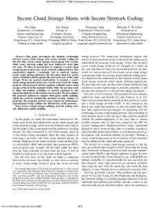
The system architecture of the sAES.
Fig. 2.
P ROPOSED H IGH P ERFORMANCE S AES S YSTEM
To achieve high throughput and low latency at the same time, we propose a highly pipelined PCI interface for sAES. Fig. 1 shows the sAES system architecture. The CPU is the master of the system. The FPGA is an accelerator of the CPU. The software on CPU has four layers: the user application layer, the encrypting file system layer, the device driver layer and the PCIe driver layer. The file read and write requests from user application will firstly send to a file system. The file system divides one request into several commands, adds the encryption or decryption instruction, and sends them to the device driver layer. The device driver reconstructs several new commands, and sends out commands to the PCIe driver. The PCIe driver sends the command to FPGA. At the same time, CPU arranges the polling of a status register on FPGA. Through the polling the status register, CPU knows which commands having been executed, and informs the file system. On FPGA, we implement a PCIe endpoint IP core, a DMA controller, an ingress Block RAM (BRAM), an egress BRAM and an AES module. The PCIe endpoint IP core is compatible with the PCIe protocol. The FPGA uses the PCIe endpoint IP core to receive or send PCIe packages. After the FPGA receives a command through PCIe, it decodes the command and sends out the read requests to get the data from CPU. The data is stored in the ingress BRAM. After all the data required by one command has been received, the AES module begins to encrypt or decrypt data. The result is stored in the egress BRAM. Finally, The FPGA sends the result back to the CPU once the data has been encrypted or decrypted. Although most accelerators are based on this architecture, we have made substantial improvements on both software and hardware. In the next two sections, we will describe more design details. A. Software Optimization The software optimization has mainly been done for the device driver layer. The optimized device driver is shown in the Fig. 2. There are a command queue, a command scheduler, command table, a TX buffer and an RX buffer in the device driver. All the works of the device driver can be separated into
−375−
Fig. 1.
The block diagram of the device driver.
two parts. One includes the operations before the acceleration. The other includes the operations after the acceleration. 1) The pre-operations before enctyption/decryption: We define the biggest block size in our system to be 4 Kbytes. We design a command queue which can store 64 commands at most. The encrypting file systems divide one file request into several commands and stored the command in the command queue. We allocate a 256 Kbytes TX buffer and a 256 Kbytes RX buffer on the CPU. We divided each of the two buffers into 64 units. The size of each unit is 4 Kbytes. We define 64 command’s IDs and arrange every command with a unique command’s ID. When there is at least one free command’s ID, the command scheduler reads one command from the command queue and arranges a command’s ID for the command. After arranging the command’s ID, command scheduler calculates the address of the TX buffer units. We allocate the TX buffer using “pci alloc consistent” function, the base address of the TX buffer is fixed. The addresses of the TX buffer can be calculated by Equation (1). tx addr = tx base addr + command� sID × 4k,
(1)
In Equation (1), the tx addr is the addresses of the TX buffer. The tx base addr is the base address of the TX buffer. After the command scheduler obtains the address of the TX buffer, it should move the data required by the command to the related TX buffer unit and move the command with the command’s ID to the command table. Then the command scheduler issues a new command and sends it to the FPGA. Because the CPU sends the base addresses of the TX buffer and the RX buffer at the system initial stage. The new command only includes 16 bits length information, 6 bits command’s ID and 1 bit control signal. The PCIe driver only needs one PIO operation to transfer one command. 2) The post-operations after encryption/decryption: After the commands are sent to the FPGA, the command scheduler begins to polling the status register of the FPGA. The status register maintains the command’s ID of the last finished command. Through polling the status register and checking the command table, the command scheduler notices the executed commands. The command scheduler obtains the command’s ID of the executed command, calculates the RX buffer address by
Fig. 3.
3) Receiving the data from the CPU: The RX CplD module reads a command from the instruction FIFO and calculates the ingress BRAM’s address using Equation (3).
In Equation (3), the Ingress BRAM addr is the address of the targeted ingress BRAM unit. After all the data required by one command is received, the DMA controller delivers the command to the instruction FIFO of the AES module, and prepares for the next command.
Egress BRAM addr = command� sID × 4k,
The block diagram of the DMA controller.
using Equation (2), and moves the results from the RX buffer to the target which is defined in the command. rx addr = rx base addr + command� sID × 4k,
(3)
4) Encrypting or decrypting the data: The AES module reads out one command, calculates the data’s address, reads the data from the ingress BRAM and encrypts/decrypts the data. The results are sent to egress BRAM unit. The address of the egress BRAM is calculated using Equation (4).
Ingress BRAM addr = command� sID × 4k,
(2)
In Equation (2), the rx addr is the addresses of the RX buffer. The rx base addr is the base address of the RX buffer. After all those operations finished, the command scheduler informs the file system the completion and releases the command’s ID. B. Hardware Optimization The main improvement of the hardware is on the DMA controller. Fig. 3 shows the block diagram of the DMA controller. The PIO Wr module is used to receive the commands from the CPU. The received commands are stored in the command FIFO. The Memory Read (MRd) module reads the command from the command FIFO, decodes the command and sends the read requests to the CPU. The RX CplD module is used to receive the CplD package from the CPU. The received data is stored in the ingress BRAM. The Memory Write (MWr) module is used to send the results to the CPU. When the FPGA receives the read request from the CPU, the read requests are sent to PIO Rd module. The DMA controller uses the TX CplD module to send the CplD package to the CPU. The DMA controller almost involved in all the operations on the FPGA. The operations related with the DMA controller can be separated into 5 steps which are shown below. 1) Receiving the commands from the CPU: The PIO Wr module receives the commands from the CPU and stores the commands into the command FIFOs. The command FIFO on the FPGA can store 64 commands at most. 2) Decoding the commands and sending the read requests to the CPU: The MRd module reads out one command, obtains the command’s ID of the command, and calculates the TX buffer address of the CPU. The MRd module should divide one command into several read requests. We develop a tag manager. The tag manager uses 32 tags to control the sending of read requests for avoiding the overflow of the CPU’s read request buffer. Once any read request is sent, this corresponding command must be sent to the instruction FIFO in the RX CplD module.
−376−
(4)
In Equation (4), the Egress BRAM addr is the address of the targeted Egress BRAM unit. After all the data required by the command is encrypted/decrypted and the results are moved to the egress BRAM, the AES module sends the command to the instruction FIFO of the MWr module. 5) Sending the data to the CPU: The MWr module reads one command from the instruction FIFO, obtains the command’s ID, calculates the address of the egress FIFO and the address of RX buffer, and divides the command into several DMA write operations. Then the MWr module reads the data from egress BRAM and sends the data to the RX buffer of the CPU. After all the data required by the command has been sent out, the FPGA updates the content of the status register on the FPGA. The status register maintains the command’s ID of the last finished command. After completing step1) to 5), we call “one command is executed”. III.
E XPERIMENTAL R ESULTS
Some applications need sAES to work in the synchronous mode, while some other systems need sAES system to work in the asynchronous mode. We will test the system performance in both modes. Our evaluation system uses an X86 workstation and a ML605 FPGA board. In the workstation, there are an Intel Core i7 quad-core CPU running at 2.93 GHz, with 8 GB physical DRAM, 8 MB L2 cache, two 16× PCIe sockets and two 8 × PCIe sockets. The Xilinx ML605 board supports the 8× Gen1.1 PCIe interface. A. The Synchronous Mode Test In the synchronous mode, we send a new command only after the execution of the previous one completed. We execute 64 commands and use the CPU to record the execution time, then calculate the throughput using Equation (5). Bs ∗ N (5) T In Equation (5), the Bs indicates the block size in one command. The N indicates the number of commands have been sent out. The T is the total execution time of all the commands. The maximum block size of our system is 4 Kbytes. We test the system performance with the block sizes of no more than 4 Kbytes. Fig. 4 shows the throughput and the latency of T hroughput =
Fig. 4. The throughput and latency results vs. the packet block size for the synchronous mode sAES.
Fig. 5. The throughput, best latency and worst latency vs. the packet block size for the asynchronous mode sAES.
our sAES system working in the synchronous mode. We can see that, as the block size increases, the throughput increases straightly. The latency is small when the block size is no more than 512 bytes. But once the block size is larger than 512 bytes, the latency increases rapidly.
When the block size is 512 bytes, Our proposed sAES achieves 10.4 Gbps throughput, the latency is 3.368 µs and 4.368 µs in the best case and worst case, respectively. The experimental results show that our proposed system achieves higher throughput and low latency with smaller block size. R EFERENCES
B. The Asynchronous Mode Test In the asynchronous mode, we fix the polling interval to 1 µs and send the commands continuously. We execute 512 commands for every different block sizes, and record the execution times. The throughput is computed using Equation (5). The maximum block size of our system is 4 Kbytes. When the block size is bigger than 4 Kbytes, the throughput is the same with the 4 Kbytes one. The Speedy PCIe only reaches a throughput of 11 Gbps with a more than 8 Mbytes block size. With a small block size, the throughput of Speedy PCIe decreases very quickly. Compare with the Speedy PCIe, the throughput of the asynchronous mode sAES can achieve 10.4 Gbps when the block size is 512 bytes, . This is 8.5 times larger compared to that of the synchronous mode sAES, and 51 times compare to the Speedy PCIe with the same block size of 512 bytes. We define the latency in the synchronous mode system is latency s. In the asynchronous mode, if just after one command is finished, the polling request comes in, the latency of the asynchronous mode is the same with latency s. This is the best case. But the command is finished just after the CPU polls the status register, the finish of this command only can be known by the CPU’s next polling operation, the latency is latency s + 1 µs. This is the worst case. Therefore, the latency is usually between the best case latency and the worst case latency. The throughput, the best case latency and the worst case latency are shown in Fig. 5. IV.
[1] [2] [3]
[4] [5] [6]
[7] [8] [9]
[10]
C ONCLUSION
We propose a high throughput and low latency data protected system. In our system, we use FPGA as the accelerator. The CPU communicates with the FPGA through PCIe interface. After the optimizations have been done at both software and hardware levels, we obtain a fully pipelined PCIe interface.
−377−
[11]
R. Bittner, “Speedy bus mastering PCI express.” In Field Programmable Logic and Applications (FPL), 2012 22nd International Conference on (pp. 523-526). IEEE. A. Behl, and K. Behl, “An analysis of cloud computing security issues.” In Information and Communication Technologies (WICT), 2012 World Congress on (pp. 109-114). IEEE. D. Modi, R. K. Agrawalla, and R. Moona, “TransCryptDFS: A secure distributed encrypting file system.” In Ultra Modern Telecommunications and Control Systems and Workshops (ICUMT), 2010 International Congress on (pp. 187-194). IEEE J. Kim, J. M. Kim, S. H. Noh, S. L. Min and Y. Cho, ”A space-efficient flash translation layer for compactflash systems.” Consumer Electronics, IEEE Transactions on 48.2 (2002): 366-375. Y. Wang, and Y. Ha, “FPGA-Based 40.9-Gbits/s Masked AES With Area Optimization for Storage Area Network.” Circuits and Systems II: Express Briefs, IEEE Transactions on 60.1 (2013): 36-40. Q. Li, and C. Zhong, “Implementation and Analysis of AES Encryption on GPU.” In High Performance Computing and Communication & 2012 IEEE 9th International Conference on Embedded Software and Systems (HPCC-ICESS), 2012 IEEE 14th International Conference on (pp. 843848). IEEE. C. Li, Q. Zhou, Y. Liu, and Q. Yao, “Cost-efficient data cryptographic engine based on FPGA.” In Ubi-Media Computing (U-Media), 2011 4th International Conference on (pp. 48-52). IEEE. S. A. Manavski, ”CUDA compatible GPU as an efficient hardware accelerator for AES cryptography.” In Signal Processing and Communications, 2007. ICSPC 2007. IEEE International Conference on (pp. 65-68). IEEE. M. Jacobsen, Y. Freund, and R. Kastner, “RIFFA: A reusable integration framework for fpga accelerators.” In Field-Programmable Custom Computing Machines (FCCM), 2012 IEEE 20th Annual International Symposium on (pp. 216-219). IEEE. G. Marcus, W. Gao, A. Kugel, and R. Manner, “The MPRACE framework: An open source stack for communication with custom FPGAbased accelerators.” In Programmable Logic (SPL), 2011 VII Southern Conference on (pp. 155-160). IEEE. D. J. Miller, P. M. Watts, and A. W. Moore, “Motivating future interconnects: a differential measurement analysis of pci latency.” In Proceedings of the 5th ACM,2009/IEEE Symposium on Architectures for Networking and Communications Systems (pp. 94-103). ACM.