checking whether the formula is true in the model provided by the design [1]. The .... describes the SAT-based verification methods, while their applications for ...
SAT-Based Verification Methods and Applications in Hardware Verification Aarti Gupta, Malay K. Ganai, and Chao Wang NEC Laboratories America, Princeton, USA {agupta, malay, chaowang} at nec-labs dot com
Abstract. Verification methods based on Boolean Satisfiability (SAT) have emerged as a promising alternative to BDD-based symbolic model checking methods. This paper provides a tutorial on various SAT-based verification methods we have developed for verifying large hardware designs. We focus separately on methods for finding bugs and for finding proofs for correctness properties, along with highlighting the many common themes that benefit these methods. We also describe practical experiences with these methods implemented in our verification platform called VeriSol (formerly DiVer), which has been used successfully in industry practice.
1 Introduction With the growing size and complexity of hardware designs, functional verification has become a bottleneck in the hardware and system development cycle. The cost of detecting bugs late in the design cycle is very high, both in terms of design re-spins and time lost to market. Simulation continues to be the primary workhorse for functional verification, primarily due to its scalability in performing dynamic analysis for a given testcase. However, its main problems are the prohibitive cost of exhaustive coverage and the practical difficulty in assessing good coverage. Formal verification techniques provide a complementary benefit to simulation, where static analysis is performed on a formal mathematical model of the given design, to check its correctness with respect to a given specification under all possible input scenarios. This provides exhaustive coverage, without any testcases, but at the expense of higher complexity of analysis. Model checking is a formal verification technique for property checking, in which the design is typically modeled as a labeled state transition system, the correctness property is specified as a temporal logic formula, and verification is performed by checking whether the formula is true in the model provided by the design [1]. The practical application of model checking is limited by the state explosion problem, i.e. the state space to be searched grows exponentially with the number of state components in the design. Symbolic model checking techniques [2, 3] typically use methods based on Binary Decision Diagrams (BDDs) [4] to symbolically manipulate sets of states and transitions without explicit enumeration. Though this improves scalability to some degree, these techniques are unable to handle the large problems M. Bernardo and A. Cimatti (Eds.): SFM 2006, LNCS 3965, pp. 108 – 143, 2006. © Springer-Verlag Berlin Heidelberg 2006
SAT-Based Verification Methods and Applications in Hardware Verification
109
encountered in current industrial practice, mainly due to an explosion in memory requirements for BDDs. As an alternative, verification methods based on Boolean Satisfiability (SAT) have emerged as a promising solution. The success of SAT-based verification methods is due primarily to the many recent advances in SAT-solvers [58] that have enabled significantly larger problems to be solved in the last decade than ever before [9]. This paper provides a tutorial on the SAT-based verification methods we have developed for the purpose of verifying large scale industry designs. We focus mainly on property checking and model checking methods. (Sequential equivalence checking can be formulated in terms of model checking, and most of the methods described here can apply equally well in that context.) We describe the main technical ideas in relationship to SAT, along with pointers to related work. For a more comprehensive survey on SAT-based verification methods, the interested reader is referred to [10]; a discussion of SAT-based combinational equivalence checking techniques can be found in [11]. Our main classification is based on whether the methods are used for finding bugs (falsification) or for finding proofs (verification)1. In the former category, we discuss primarily Bounded Model Checking (BMC) [12] and its enhancements [13-15], while the latter category includes methods based on induction [16, 17], Unbounded Model Checking (UMC) [18-21], and proof-based iterative abstraction [22, 23]. In our experience, both falsification and verification methods are required for handling hardware verification problems in an industry setting. Furthermore, there are many common themes that benefit methods in both categories. In particular, we highlight the benefits of using an efficient circuit representation that supports on-the-fly simplifications [24]. We also exploit a hybrid SAT solver [25] that combines the benefits of circuit-based and CNF-based SAT solving techniques. It is useful for the circuit representation to also support symbolic manipulation through BDDs, and we describe many methods that combine SAT and BDDs to derive their complementary benefits in significantly enhancing the performance or scalability of the overall application. Another common theme is the use of bounded unrolling of the design (also called time frame expansion in related work on automatic test pattern generation [26]) to cast the associated problem as a SAT problem. This has been utilized by many falsification as well as verification methods. We use this feature most effectively for handling embedded memories, where our Embedded Memory Modeling (EMM) techniques abstract out the explicit memory elements, but add the data forwarding and other memory modeling constraints at each step of the unrolling [27]. This avoids the state space explosion of modeling the memory state, while preserving the accuracy of verification. Again, the EMM techniques have been used in both falsification [27] as well as verification methods [28]. We also describe practical experiences with these methods implemented in our verification platform called VeriSol (formerly DiVer), which has been used successfully in industry practice for the last four years to verify large hardware designs [29]. In addition to verifying correctness properties specified by a user on 1
Although these categories correspond quite naturally to bounded and unbounded verification, respectively, we would like to avoid overloading the term bounded, since many verification methods we describe here use bounded design unrolling for unbounded verification.
110
A. Gupta, M.K. Ganai, and C. Wang
RTL (Register Transfer Level) designs, it has also been used for checking automatically generated properties. Specifically, VeriSol has been integrated within a high level behavioral synthesis system called Cyber [30]. The Cyber system automatically generates RTL designs from high-level behavioral descriptions. In addition, it automatically generates correctness properties for these RTL designs also. The back-end property checking for Cyber can be performed by VeriSol. We have also added the capability of generating automatic correctness properties for typical Verilog RTL designs. More recently, we have also used many of our SAT-based verification methods for performing the back-end verification in a system called F-Soft, which is targeted for verifying software programs [31, 32]. The F-Soft verification platform combines several recent advances in formal verification, including SAT-based verification, static analyses, and predicate abstraction. Basically, we accurately model the program behavior as a finite state symbolic model (under assumptions of finite data and control), use static analyses to reduce the size of the verification model, and perform back-end model checking using VeriSol. Although we will not describe the software verification applications in this paper, it is interesting to note that by adding several customized heuristics for software, our SAT-based methods in VeriSol could be applied successfully for verifying models generated from software programs. Finally, we would like to note that there has been a lot of interest in applying SAT solver techniques to decision procedures for richer logics, such as quantifier-free fragments of first order logic [33, 34] . In our own work, we have proposed new solvers for difference logic, called SLICE [35] and SDSAT [36]. Since SAT solvers and such decision procedures provide essential components of many theorem provers, the SAT-based verification methods described here can be naturally extended to provide a bridge from model checking to theorem proving applications. The paper is organized as follows. Section 2 briefly reviews the terminology and background for the basic SAT algorithms and model checking techniques. Section 3 describes the SAT-based verification methods, while their applications for hardware verification in a practical industry setting are described in Section 4. Finally, we conclude in Section 5.
2 Background 2.1 Boolean Satisfiability (SAT) Problem The Boolean Satisfiability (SAT) problem is a well-known constraint satisfaction problem, with many applications in the fields of VLSI Computer-Aided Design (CAD) and Artificial Intelligence. Given a propositional formula, the Boolean Satisfiability problem is to determine whether there exists a variable assignment under which the formula evaluates to true. The SAT problem is known to be NP-Complete [37]. In practice, there has been tremendous progress in SAT solver technology over the years, summarized in a survey [9]. Most SAT solvers use a Conjunctive Normal Form (CNF) representation of the Boolean formula. In CNF, the formula is represented as a conjunction of clauses, each clause is a disjunction of literals, and a literal is a variable or its negation. Note that in
SAT-Based Verification Methods and Applications in Hardware Verification
111
order for the formula to be satisfied, each clause must also be satisfied, i.e., evaluate to true. A Boolean circuit can be encoded as a satisfiability equivalent CNF formula [38]. Alternatively, for SAT applications arising from the circuit domain, the SAT solver may be modified to work directly on the Boolean circuit representation.
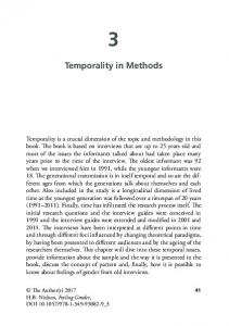
SAT_Solve(P=1) { // Check if constraint P=1 satisfiable? while(Decide()=SUCCESS) //Selects a new variable while(Deduce()=CONFLICT)//BCP till conflict/no-conflict if (Diagnose()=FAILURE) //Add conflict learnt clause(s) return UNSAT;//Conflict found at decision level 0 return SAT;} //No more decision to make
Fig. 1. DPLL style SAT Solver
Most modern SAT solvers are based on a DPLL-style [39] as shown in Figure 1 with three main engines: decision, deduction, and diagnosis. All these engines have seen remarkable progress in the last few years, e.g. the VSIDS decision heuristic and the lazy two-literal watching scheme for deduction in Chaff [6], and the conflict analysis and conflict-driven learning in Grasp [5]. Conflict-driven learning results in addition of conflict clauses to the SAT problem in order to prevent the same conflict from occurring again during the search. Additionally, information recorded during conflict analysis has been used very effectively to provide a proof when a formula is determined to be unsatisfiable by the SAT solver. This proof can be independently checked to verify the SAT solver itself [40, 41]. These techniques can also be easily adapted to identify a subset of clauses from the original problem, called the unsatisfiable core [40, 42], such that these clauses are sufficient for implying unsatisfiability. The use of such techniques in verification methods are described in more detail in Section 3.2.2. 2.2 Circuit-Based and Hybrid SAT Solvers SAT has many applications in the logic circuit domain, such as automatic test pattern generation (ATPG), verification, timing analysis. The Boolean problem in these applications is typically derived from the circuit structure. This has also led to interest in circuit-based SAT solvers [43-45] that work directly on the circuit structure, and use circuit-specific heuristics to guide the search. In general, attempts to include circuit structure information into CNF-based SAT solvers have been unsuccessful due to their significant overhead. Before we compare circuit-based and CNF-based SAT solvers, it is instructive to consider how each performs Boolean Constraint Propagation (BCP) which constitutes the core of most deduction engines, and typically consumes 80% of the SAT runtime. Circuit-based BCP is typically performed by using a lookup table for fast implication propagation [45]. Based on the current values of the inputs and output of the circuit node, the lookup table determines the next “state” of the gate where the state
112
A. Gupta, M.K. Ganai, and C. Wang
encapsulates any implied values and the next action to be taken for the node. The implication algorithm is iterated over the entire circuit graph. For each vertex, it determines new implied values and the direction for further processing. As an example, Figure 2 (from [45]) shows some cases from the implication lookup table for a two-input AND gate. Note that only one case, a logical 0 at the output of an AND vertex, requires a new case split to be scheduled for justification. All other cases either cause a conflict and backtracking, or further implications, or a return to process the next element to be justified. Due to its low overhead, this table lookup-based implication algorithm is very efficient in practice. Next
Current 1
Action
1 X
X
X
STOP
X
0
0 1
X
1
CONFLICT
0
CASE_SPLIT
X
X
X 0
X
X
0
0 X
X
X
X
1 1
X
0
PROP_FORWARD
1
PROP_LEFT_RIGHT
1
...
...
...
Fig. 2. Lookup Table for Fast Implication Propagation on a 2-input AND Gate
For CNF-based BCP, consider the lazy two-literal watching scheme proposed by Chaff [6] : • • •
For each clause, only two literals are monitored for state change. The clause state is updated lazily when a variable is assigned, i.e., only when the two monitored literals coincide. It does not require state change for clauses during the backtracking process, thus unassigning a variable takes constant time.
For clauses with many literals, this lazy update works significantly better than other BCP schemes like those in SATO [7], and GRASP [5]. It avoids unnecessary lookups for a clause, thereby significantly improving the underlying cache behavior and the resulting performance. To get back to the comparison between circuit-based and CNF-based BCP, note that there is an inherent overhead built into the translation of circuit gates into clauses. A two-input gate translates to three clauses in the CNF approach, while in the circuitbased approach a gate is regarded as a monolithic entity. Therefore, in the circuit approach an implication across a gate requires a single table lookup, while in the CNF approach it requires processing multiple clauses. In addition, the CNF-based BCP in Chaff does not keep track of the clauses that have been satisfied in order to reduce overheads. However, there is an inherent cost associated with visiting the satisfied clauses. Specifically, even if a clause gets satisfied due to an assignment to some
SAT-Based Verification Methods and Applications in Hardware Verification
113
un-watched literal, the watched literal pointers could still get updated. Overall, for the generally small clauses arising from circuit gates, these differences translate to significant differences in BCP time, usually in favor of the circuit-based approach. On the other hand, learned conflict clauses arising from conflict analysis are typically much larger than those arising from two-input gates. Adding a large learned clause as a gate tree can lead to a significant increase in the size of the circuit. This in turn, can increase the number of implications, thereby negating any potential gains obtained from circuit-based BCP. For such clauses, it is more useful to maintain them as monolithic clauses and take advantage of CNF-based two-literal watching and lazy update to process them efficiently. Based on these observations, we proposed a hybrid SAT solver [25] to combine the relative benefits of CNF-based and circuit-based SAT solvers. In our scheme, the original circuit problem is represented as a gate-level netlist, while the learned conflict clauses are represented in CNF. The hybrid BCP engine consists of table lookups for the gates, and a Chaff-style two-literal watching scheme for the conflict clauses, thereby combining the advantages of both. Furthermore, a hybrid representation of the Boolean problem also allows exploitation of both circuit-based and CNF-based decision heuristics. In particular, we effectively exploit the justification frontier heuristic [43], which restricts the decision nodes to be those that justify the values on their fanout node. The use of this heuristic further improves performance in many practical instances of SAT problems arising in circuit applications. We typically obtained speedup by a factor of two, in comparison to a pure CNF-based approach. Since SAT is a core engine in many verification applications like equivalence checking and BMC, a consistent speedup can prove to be very significant in practice. Furthermore, any future improvements in the performance of circuit-based and CNF-based SAT solvers can directly translate into improvements of the hybrid SAT solver as well. In related work, Kuehlmann et al. [46] used circuit-based SAT in combination with other useful techniques like BDD sweeping and dynamic circuit transformation for combinational equivalence checking. However, they did not propose any effective way to perform conflict-driven learning with conflict clauses represented as large ORtree circuits. Other more recent efforts have also combined the advantages of multiple symbolic representations including circuit graphs, SAT, and BDDs [47, 48], and used these ideas along with additional conflict-driven learning, in order to improve the SAT solver performance [11]. 2.3 Model Checking In model checking [1], the design is typically modeled as a labeled state transition system, the property is specified as a temporal logic formula, and verification consists of checking whether the formula is true in that model. Temporal logics are very useful for specifying dynamic behavior over time. Different variants of temporal logics have become popular, such as Linear Temporal Logic (LTL) and Computation Tree Logic (CTL), depending on whether a linear or a branching view of time is considered, respectively. In this paper, we focus mainly on simple safety properties, denoted as AGp. This formula specifies that on all(A) paths of a system, globally (G) in each state of the path, the property p holds. Such properties can be verified by an exhaustive
114
A. Gupta, M.K. Ganai, and C. Wang
traversal of the state space to check that p holds in every reachable state. This state space traversal forms the computational core of most model checking techniques. Explicit state model checkers, such as SPIN [49], use an explicit representation of the states and transitions in the system, and enumerate all reachable states explicitly. They utilize many additional techniques such as state hashing for compaction of state representations, and partial order methods to avoid exploring all interleavings of concurrent processes. The scalability issue in explicit state enumeration makes these checkers unsuitable for hardware designs, although they have found practical success in verification of controllers and software. In contrast, symbolic model checkers, such as SMV [3], avoid an explicit enumeration of the state space by using symbolic representations of sets of states and transitions. They typically use BDDs, which provide a canonical representation of Boolean formulas and efficient symbolic manipulation algorithms. For hardware designs, where these symbolic representations effectively capture the regularity in the state-space, symbolic model checking has significantly extended the ability to handle large state spaces. The core steps in symbolic model checking are the image/pre-image computations, which compute the set of states reachable in one step from/to a given set of states via the transition relation, as follows: Img(Y) = SN(Y) = ∃ X,W. SC(X) ∧ T(X,Y,W)
(1)
PreImg (X) = SC(X) = ∃ Y,W. SN(Y) ∧ T(X,Y,W)
(2)
Here, the variable sets X, Y, W, denote the present state, next state, and primary input variables, respectively; and SC , SN and T denote the next states, the current states, and the transition relation, respectively. When these state sets and the transition relation are represented symbolically as BDDs (or its variants), these computations can be performed symbolically by using the BDD-based operations for conjoining and existential quantification. However, for many large designs, these BDD-based operations can cause a blow up in memory size. A basic algorithm for symbolic model checking simple safety properties can be formulated as shown in Figure 3. Let B be the set of bad states, in which property p does not hold, and I the set of initial states. It represents sets of states symbolically, and searches for bad states in breadth first order starting from the initial states. 1. model-check(I,T,B) 2. SC =∅; SN = I; 3. while SC ≠ SN do 4. SC = SN ; 5. if B ∩ SC ≠ ∅ then 6. return ``found counter-example''; 7. SN = SC ∪ Img(SC); 8. done; 9. return ``no bad state reachable'';
Fig. 3. Forward model checking algorithm for simple safety properties
SAT-Based Verification Methods and Applications in Hardware Verification
115
This forward model checking algorithm starts at the initial states and searches forward along the transition relation, relying on the symbolic image computation described earlier. Similarly, there are backward model checking algorithms, which search backward from the bad states, and rely on the symbolic pre-image computation.
3 SAT-Based Verification Methods We start by describing methods specialized for finding bugs in hardware designs. Most of these are based on the Bounded Model Checking (BMC) framework proposed by Biere et al. [12]. In the second half of this section, we focus on methods targeted for finding proofs. Many of these use our efficient BMC framework and add techniques on top to provide completeness of verification. We also describe additional techniques for proof-based abstraction and unbounded model checking using SAT. 3.1 Methods for Finding Bugs Despite the considerable benefits of symbolic model checking using BDDs, the basic verification approach of exhaustive analysis does not scale well in practice. An alternative is the use of falsification approaches which focus primarily on the search for finding bugs. One of the most popular falsification approaches is Bounded Model Checking (BMC) [12]. We describe the basic BMC framework, followed by various performance enhancements, and a distributed BMC framework useful for overcoming memory limitations of a single workstation environment. We also describe EMM techniques which allow efficient handling of embedded memories in hardware designs for BMC applications. 3.1.1 Bounded Model Checking (BMC) In BMC, the problem of searching for a counter-example of length k is translated to a Boolean formula such that the formula is satisfiable if and only if there exists a counter-example of length k. Effectively, the translation to a Boolean formula is performed by unrolling the transition relation of the design for k time frames, and adding appropriate constraints due to the property. The satisfiability check is typically performed by using a Boolean SAT solver in the back-end. In this paper, we consider the following notation and formulation of BMC. The design is described as a Kripke structure M = (S, I, T, L), with a finite set of states S, a set of initial states I, a transition relation between states T, and a labeling L of states with atomic propositions. Let T(x,y,w,z) denote the symbolic transition relation in terms of present state variables x, next state variables y, primary input variables w, and intermediate variables z. Let yk denote the symbolic state (in terms of latch variables) after k time frames in the unrolled design. In addition, we can also consider environmental constraints on variables (signals) e in the design, which are required to hold in every time frame. Definition 1. We use the following Boolean formula, denoted BMC(M,f,k), to check the existence of a k-length witness for property f: BMC(M, f, k) = I(y0) ∧ 1≤ j ≤ k [ T(xj,yj,wj,zj) ∧ ( y j-1 = xj )] ∧ 0 ≤ j ≤ k [Env(ej)] ∧ 〈 f 〉k
116
A. Gupta, M.K. Ganai, and C. Wang
Here, the different sets of constraints are described as follows: 1. 2. 3.
4. 5.
I(y0) : Initial state constraints on initial state y0 T(xj, yj, wj, zj) : Transition relation constraints for time frame j, 1 ≤ j ≤ k (yj-1 = xj ) : Latch interface propagation constraints, 1 ≤ j ≤ k, which capture the propagation of latch inputs in one time frame to the latch outputs in the next time frame Env(ej) : Environmental constraints on signals e in each time frame j, 0 ≤ j ≤ k 〈 f 〉k : Constraints due to property translation of formula f in time frames up to k
Verification typically proceeds by looking for witnesses or counter-examples (CE) of increasing length until some completeness threshold [12, 50] is reached. The overall algorithm of a SAT-based BMC procedure for checking (or falsifying) a simple safety property AG p is shown in Figure 4, where Unroll corresponds to an unrolling of the symbolic transition relation of the design, and P corresponds to the circuit representation of the proposition p. Note that the SAT problems generated by the BMC translation procedure grow bigger as k increases. Therefore, the practical efficiency of the backend SAT solver becomes critical in enabling deeper searches to be performed. BMC(k,P){//Falsify safety property AG p within bound k for (int i=0; i