Review
TRENDS in Biotechnology
Vol.22 No.7 July 2004
Scaffold-based tissue engineering: rationale for computer-aided design and solid free-form fabrication systems Dietmar W. Hutmacher1, Michael Sittinger2 and Makarand V. Risbud3 1
Division of Bioengineering and Department of Orthopaedic Surgery, National University of Singapore, 119260, Singapore German Rheumatism Research Center and Experimental Rheumatology and Tissue Engineering Laboratory, Department of Rheumatology and Clinical Immunology, Charite´, Humboldt University of Berlin, 10117 Berlin, Germany 3 Graduate Program in Cell and Tissue Engineering and Department of Orthopaedic Surgery, Thomas Jefferson University, Philadelphia 19107, USA 2
One of the milestones in tissue engineering has been the development of 3D scaffolds that guide cells to form functional tissue. Recently, mouldless manufacturing techniques, known as solid free-form fabrication (SFF), or rapid prototyping, have been successfully used to fabricate complex scaffolds. Similarly, to achieve simultaneous addition of cells during the scaffold fabrication, novel robotic assembly and automated 3D cell encapsulation techniques are being developed. As a result of these technologies, tissue-engineered constructs can be prepared that contain a controlled spatial distribution of cells and growth factors, as well as engineered gradients of scaffold materials with a predicted microstructure. Here, we review the application, advancement and future directions of SFF techniques in the design and creation of scaffolds for use in clinically driven tissue engineering. Currently, scaffold-based tissue engineering strategies are expanding to encompass cells, bioactive molecules and structural matrices. Each of these components is combined into a ‘construct’ that promotes repair and – in the best case scenario – regeneration of damaged or diseased tissues. Because many scaffold-based tissue-engineering approaches are still experimental, it is not yet clear what defines a so-called ‘ideal scaffold’. Factors governing scaffold design are complex and include considerations of matrix architecture, pore size and morphology, mechanics versus porosity, surface properties and degradation products. Moreover, because scaffolds are often composite structures, other confounding variables include the composition of biological components and variation of these and other factors with time. It could be argued that there is no ‘ideal scaffold’ design per se, instead each tissue requires a specific matrix design with defined material properties. Scaffold design should therefore begin with at least a set of minimum biochemical and physical requirements [1]. The scaffold must provide sufficient mechanical strength and stiffness to substitute initially for wound contraction forces, and later for the Corresponding author: Dietmar W. Hutmacher (
[email protected]).
remodelling of the tissue. Furthermore, scaffold architecture should enhance initial cell attachment and subsequent migration into the matrix; it must also enhance the mass transfer of metabolites and provide sufficient space for remodelling of the organized tissue matrix and development of a vasculature. To achieve this goal, the scaffold degradation profile should be designed so that it supports the construct until neotissue (cells plus organized extracellular matrix without vascularization) is formed [1]. A second important consideration is that if the degradation profile is slow the 3D matrix will maintain structural integrity and mechanical properties during the in vitro and/or in vivo remodelling process. Factors affecting the rate of remodelling include the type of tissue and the anatomy and physiology of the host tissue [2]. The external size and shape of the construct must also be considered, particularly if the scaffold or cell construct is customised for an individual patient. It is also imperative that scaffolds are manufactured in a reproducible, controlled, and cost-effective fashion with the flexibility to accommodate the presence of biological components, such as cells and growth factors, in certain applications [3,4]. To date, two methods of incorporating cells into scaffolds are being explored: (i) seeding of cells onto the surface of the scaffold following fabrication and (ii) the incorporation of cells into the scaffold fabrication process. In terms of organ printing, the second process is of considerable interest. However, early results reflect success with printing cell monolayers and not a complete 3D tissue or organ [5]. Basic considerations for scaffold fabrication by SFF Advanced mouldless manufacturing techniques, commonly known as solid free-form fabrication (SFF), rapid prototyping (RP) or, more colloquially, art to part technology [6] have recently been used for fabricating complex shaped scaffolds. Unlike conventional machining, which involves constant removal of materials, SFF builds parts by selectively adding materials, layer by layer, as specified by a computer program. Each layer represents the shape of the cross-section of the model at a specific level. Today, SFF is viewed as an efficient way of reproducibly generating scaffolds of desired properties on a large scale [4,7,8]. In
www.sciencedirect.com 0167-7799/$ - see front matter q 2004 Elsevier Ltd. All rights reserved. doi:10.1016/j.tibtech.2004.05.005
Review
TRENDS in Biotechnology
addition, one of the potential benefits of SFF technology is the ability to create parts with highly reproducible architecture and compositional variation. Over the past two decades, .20 RP systems were developed and commercialised [9] with a focus on the rapid manufacturing of prototypes for non-biomedical applications. Very recently, biomaterial scientists used these technologies to fabricate scaffolds for tissue engineering. SFF techniques offer unique ways to precisely control matrix architecture (size, shape, interconnectivity, branching, geometry and orientation) yielding biomimetic structures varying in design and material composition, thereby enhancing control over mechanical properties, biological effects and degradation kinetics of the scaffolds. RP techniques can be easily automated and integrated with imaging techniques to produce scaffolds that are customised in size and shape allowing tissue-engineered grafts to be tailored for specific applications or even for individual patients (Figure 1). A recent milestone in scaffold fabrication by SFF was the development of solvent-free and aqueous-based systems. By allowing inclusion of bioactive components, such as growth factors, cells and drugs, these systems offer new opportunities in tissue engineering and regenerative medicine. In the following sections we discuss the state of the art in SFF techniques applied to scaffold fabrication. We have classified the SFF systems based on their processing technology. Future directions in the design and manufacturing of novel and patient-specific matrices (a)
for clinically relevant bone-engineering applications will also be discussed. SFF techniques used in scaffold fabrication Systems based on laser technology Stereolithography apparatus. Stereolithography (SLA) is often considered the pioneering RP technique with the first commercial system introduced in 1988 by 3D Systems Inc. (www.3dsystems.com). This technique is based on the use of a UV laser that is vector scanned over the top of a bath of a photopolymerisable liquid polymer material. As polymerisation is initiated, the laser beam creates a first solid plastic layer, at, and just below the surface of the bath. This laser polymerisation process is repeated to generate subsequent layers by tracing the laser beam along the design boundaries and filling in the 2D crosssection of the model, layer-by-layer. Once the model is complete, the platform is raised out of the vat and the excess resin is drained. The model is cured in a UV oven and finished by smoothing the surface irregularities. Resolution of a standard SLA layer is determined by the elevator layer resolution (up to 1.3 mm) and laser spot size (80 –250 mm) [10]. The use of SLA in the biomedical industry is currently limited to the creation of anatomical models for surgical planning or teaching [11,12]. Because of curing and shrinkage after post-processing a shortfall of the SLA model is compromised resolution [13]. Also, due to absorption and scattering of the laser beam, a pronounced
(b)
(d)
355
Vol.22 No.7 July 2004
(c)
(e)
(f)
(g) defect
TRENDS in Biotechnology
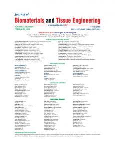
Figure 1. Tissue engineering of patient-specific bone grafts. This innovative treatment protocol uses medical imaging, computational modelling and bioresorbable scaffold fabricated with rapid prototyping (RP) technique. CT scan data of the patients bone defect (a) are used to generate a computer-based 3D model (b). This model is then imported into RP system software to be ‘sliced’ into thin horizontal layers, with the tool path specified for each layer (c). The ‘sliced’ data are used to instruct the RP machine (d) to build a scaffold (e) layer by layer, based on the actual shape of the computer model (c). RP technology produces excellent templates for the treatment of intricate bone defects (a and f). Custom-made scaffold and cell constructs (g, see arrows) exactly follow the complex shaped 3D contour of the skull. www.sciencedirect.com
356
Review
TRENDS in Biotechnology
‘deformation’ occurs when smaller and more intricate objects are fabricated. Generally, the manufactured part is weak at the time of removal and needs post-processing for further curing [10,13]. It is noteworthy that there is a limited choice of photopolymerisable biomaterials that have the required biodegradability and biocompatability, mechanical stability and other prerequisite properties for scaffold applications. Examples of photopolymerisable macromers include derivatives of polyethylene glycol (PEG) acrylate, PEG methacrylate, polyvinyl alcohol (PVA) and modified polysaccharides such as hyaluronic acid and dextran methacrylate. Polypropylene fumarate, anhydride and polyethylene oxide (PEO) precursor systems could be explored because investigations are underway for their clinical use as curable bioadhesives or injectables. Cooke et al. recently demonstrated the feasibility of using the SLA process to build and control 3D multilayer parts made from a biodegradable, biocompatible resin polypropylene fumarate [14]. Likewise, Matsuda and Mizutani have developed a biodegradable, photocurable copolymer, acrylated capped poly-1-caprolactone-co-trimethylene carbonate to be used with the SLA apparatus to prepare photoconstructs such as microneedles, a microcylinder and microbanks on surfaces [15]. Based on such encouraging results micro stereolithography (mSL) in particular offers great potential for the production of 3D polymeric structures with micrometer resolution. Recently, mSL was also tested for fabricating high aspect ratio and complex 3D microstructures [16,17]. Selective laser sintering. The selective laser sintering (SLS) technique uses a CO2 laser beam to sinter thin layers of powdered polymeric materials, forming solid 3D objects. During SLS fabrication, the laser beam is selectively scanned over the powder surface following the crosssectional profiles carried by the slice data. The interaction of the laser beam with the powder raises the powder temperature and sintering occurs at just beyond the glass transition temperature causing the particles to fuse together to form a solid mass. Subsequent layers are built directly on top of previously sintered layers with new layers of powder being deposited by a roller [18]. Rimell and Marquis have reported the fabrication of clinical implants using a simplified selective laser sintering apparatus and ultra high molecular weight polyethylene (UHMWPE) [19]. It was observed that solid linear continuous bodies could be fabricated, but material shrinkage occurred when a sheet-like structure was desired. The porosity of the material formed was also a concern. The material exposed to the laser beam was seen to undergo degradation in terms of chain scission, cross-linking and oxidation. It was concluded that to apply this technology to the fabrication of UHMWPE devices requires the development of improved starting powders with increased density. Lee and co-workers were the first to use SLS to manufacture ceramic bone implants [20]. The augmentation of alveolar ridge defects in canines was conducted to assess the safety and efficacy of these SLS-fabricated calcium phosphate (CaP) implants [21]. Histological evaluation revealed that the implant material was biocompatible and mineralized bone was formed in the macro pores. Griffith www.sciencedirect.com
Vol.22 No.7 July 2004
and Halloran have reported the fabrication of ceramic parts using suspensions of alumina, silicon nitride and silica particles in a UV photocurable monomer by SLA [22]. Using a similar technique, a suspension of hydroxyapatite (HA) in a photocurable monomer was formulated to produce scaffolds for orbital floor prosthesis [23]. It was concluded that for bone graft applications HA scaffolds provide a superior cosmetic appearance compared with conventional techniques [23]. Porter et al. formulated suspensions of calcium polyphosphate (CPP) and a photocurable monomer for forming bioresorbable skeletal implants using SLA [24]. Sintering CPP at 6008C for 1 h produced a crystalline material (average porosity of 22.9%) exhibiting superior bend strength and toughness compared with amorphous CPP. Tan et al. used different compositions of non-degradable polyetheretherketone (PEEK)/HA powder blends to assess their suitability for SLS processing. [25]. System based on print technology – 3D printing. 3D printing (3DP) technology was developed at MIT [3] and became one of the most investigated SFF techniques in tissue engineering and drug-delivery applications [26 –31]. An advantage of 3DP is that it can be performed in an ambient environment. The 3D printer constructs the 3D model by first spreading a layer of fresh powder over a building platform. An ‘inkjet’ print head prints or deposits the binder solution onto the powder bed. After the 2D layer profile is printed, a fresh layer of powder is laid down. The printing cycle continues and the layers merge together when fresh binder is deposited until the whole part is completed. After the binder has dried in the powder bed, the finished component is retrieved and unbound powder removed. However, if the part is designed to be porous, one drawback of a powder-supported and powder-filled structure is the difficulty in removing internal unbound powder. The resolution of the 3D printer is also limited by the nozzle size and the degree of control allowed over the position controller that defines print head movement. In addition, the particle size of the powder governs the layer thickness (usually 80 – 250 mm). In the context of tissue-engineering scaffolds, base biomaterials are not usually available in powder form and require special preprocessing for 3DP [26– 28]. The surface roughness and aggregation properties of the powdered materials also affect the component resolution and efficiency of removal of trapped materials [29,31]. Work by Lam et al. demonstrated the feasibility of using natural biopolymers (starch, dextran and gelatin) and distilled water as the binder [31]. This aqueous system eliminated the problem linked to the use of an organic solvent. However, the scaffold is bound by water and is therefore water-soluble, necessitating a lengthy postprocessing step to ‘waterproof ’ the product. This work also showed that owing to non-elimination of all the microspaces and gaps present between the fused powdered particles, scaffolds manufactured by 3DP possessed a second tier of porosity referred to as ‘microporosity’. This microporosity is probably created at random and could be integral in the degradation kinetics of the scaffold.
Review
TRENDS in Biotechnology
Assembly technology-based systems Shape deposition manufacturing. The term shape deposition manufacturing (SDM) was initially introduced for the fabrication of scaffolds for bone tissue engineering [32]. It involves the fabrication of a layered scaffold in a customised geometry by processing the clinical imaging data and translating it to the desired scaffold layer (,1 mm) by a computer-numerically-controlled cutting machine (http://www-2.cs.cmu.edu/People/tissue/front_page.html). This technique employed the simultaneous addition of cells to the matrix during 3D scaffold fabrication. In a published study, the scaffolds were incrementally built up from prefabricated cross-sectional layers of foams [,1 mm thick, made from blends of polycaprolactone (PCL) and poly D,L lactide-co-polyglycolide (P[D]LGA) combined with HA granules]. Layers were manually stacked up and joined to form 3D discs with biodegradable or nonbiodegradable fasteners. Each prefabricated layer was first seeded with cells and growth factors before final assembly. Although unique, this technique is dependent on the quality of the fabricated foam, which is generated by a conventional method. Similarly, because this technique is still in its infancy, assembly is not automated. Furthermore, to avoid trapping of seeded cells within each layer, the assembly process needs to be controlled so that there is sufficient pore interconnectivity. The concept of a novel robotic micro-assembly technique was first published in 2000 [1] and recently the first prototype system was developed and fabricated and the parts were successfully made [33,34]. The principle of micro-assembling a functional tissue-engineering scaffold is based on the same concept as assembling a structure using small building-block units like Legow. Building blocks of different designs are first fabricated using lithography, or other microfabrication technologies. Then the blocks are assembled by a computer-controlled, dedicated precision robot with four degrees of freedom and micro-gripping capabilities (Figure 2). The final result is a tissue graft built out of cells and different materials with the required biochemical and physical properties. The application of advanced microfabrication techniques such as silicon micro-machining and polymer replica moulding for tissue engineering of complex tissues has been described [35,36]. The goal of this work was to produce organ templates having feature resolution of 1m, well in excess of that necessary to fashion the capillaries comprising the microcirculation of the organ. Initial efforts have resulted in high-resolution polymer scaffolds produced by replica moulding from silicon micro-machined template wafers. These scaffolds have been successfully seeded with endothelial cells in channels with dimensions as small as the blood capillaries [35,36]. Extrusion technology-based systems. Techniques such as fused deposition modelling (FDM), 3D plotting, multiphase jet solidification (MJS) and precise extrusion manufacturing (PEM) employ extrusion of a material in a layered fashion to build a scaffold. Depending on the type of machine, a variety of biomaterials can be used for scaffold fabrication. www.sciencedirect.com
Vol.22 No.7 July 2004
357
A traditional FDM machine consists of a head-heated liquefier attached to a carriage moving in the horizontal xy plane [37]. The function of the liquefier assembly is to heat and pump the filament material through a nozzle directly on to the build platform following a programmed path. Once a layer is built, the platform moves down one step in the z direction to deposit the next layer. Parts are made layer by layer with the layer thickness varying in proportion to the nozzle diameter. FDM is restricted to the use of thermoplastic materials with good melt viscosity properties; cells cannot be encapsulated into the scaffolds during the fabrication process. An interdisciplinary group in Singapore has studied and patented the parameters for processing PCL and several composites (PCL/HA, PCL/TCP etc.) by FDM [38]. These first generation scaffolds (PCL) have been studied for more than three years with, and without, cells in a clinical setting (http://www.osteopore-intl.com). The second generation scaffolds for bone engineering using FDM were made of polymer and CaP composites because they confer favourable mechanical and biochemical properties, including strength via the ceramic phase, toughness and plasticity via the polymer phase, favourable degradation and resorption kinetics and graded mechanical stiffness. Other advantages include improvement of cell seeding, and the enhanced incorporation and immobilization of growth factors. Endres et al. [39] and Rai et al. [40] have tested these PCL/CaP composite scaffolds for bone engineering and reported encouraging results (Figure 3). Woodfield et al. used a FDM-like technique for producing scaffolds made of polyethylene glycolterephthalate-polybutylene terepthalate (PEGT/PBT) [41,42]. By varying PEGT/PBT composition, porosity and pore geometry, scaffolds were produced with a range of mechanical properties for engineering of articular cartilage. A variation of the FDM process, the precision extruding deposition (PED) system, was developed and tested at Drexel University [43]. The major difference between PED and conventional FDM is that the scaffolding material can be directly deposited without filament preparation. Pelletformed PCL is fused by a liquefier temperature provided by two heating bands and respective thermal couples and is then extruded by pressure created by a turning precision screw. Several groups [44– 51] and companies (Envisiontec; http://www.envisiontec.de, Sciperio; http://www.Sciperio. com) have developed SFF machines that can perform extrusion of strands or filaments and/or plotting of dots in 3D (Figure 4). These systems are built to make use of a wide variety of polymer hotmelts as well as pastes or slurries, solutions and dispersions of polymers and reactive oligomers. One such technique, MJS, involves the extrusion of a melted material through a nozzle, which has a jet-like design. The MJS process is usually used to produce metallic or ceramic parts via a lost-wax method. Poly (D,L)-lactide structures for bone and cartilage tissue engineering have been fabricated using a MJS machine built by the Frauenhofer Institue, Stuttgart [44]. The scaffolds had a pore size of 300– 400 mm and supported ingrowth of human bone tissues. Calvert et al. built an
Review
358
TRENDS in Biotechnology
Vol.22 No.7 July 2004
(b)
(a) Articular cartilage
60µm 500µm
Defect Bone 200µm Introduce bone cells from the patient
90µm Biometric surface
Scaffold
60µm
(c)
Grow into an artificial bone Transplantation
(d)
(e)
Visual feedback through a microscope θ
Micro-gripper 60µm Haptic interface
y x x-y-z table TRENDS in Biotechnology
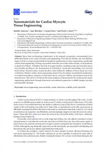
Figure 2. Hutmacher’s group is developing a novel method based on robotic micro-assembly to fabricate scaffold and cell constructs for a variety of tissue-engineering applications (a). The concept is based on the assembly of microscopic Legow-like building blocks into a scaffold (b,c). The computer-controlled and automated system allows the control of distribution of growth factors and living cells within the scaffold in 3D (d) so that scaffold and cell constructs with customised biological and physical properties can be developed. The micro-assembly is carried out using an in-house designed precision robot. u represents the angle that the gripper can rotate round its own axis (3608) A two-finger microgripper (e, arrow) was developed to grasp, move and assemble the microparts. Building blocks were fabricated using micro stereolithography (mSLA) and a micro-electro-mechanical systems (MEMS) technique (c), which has the capability of mass production of micro-objects with complex shapes and high precision at an economical cost [33,34].
in-house extrusion-based system that could fabricate scaffolds with a resolution of , 0.5 mm and typical layer heights of 0.2 – 1.0 mm [45 –47]. Xiong et al. have developed a RP machine termed PEM and fabricated porous poly L-lactic acid (PLLA) with tricalcium phosphate (TCP) scaffolds for bone tissue engineering [48]. Landers et al. [49] used the term ‘bioplotter’ to describe the fabrication of scaffolds of different composition. Versatility of this technique was demonstrated in several other studies [50 – 52]. A study compared 3DP and 3D bioplotting for the manufacture of biodegradable polyurethane scaffolds using aliphatic polyurethanes based on lysine ethyl ester diisocyanate and isophorone diisocyanate [53]. Layer-by-layer construction of the scaffolds www.sciencedirect.com
was performed by 3DP (i.e. bonding together starch particles followed by infiltration and partial crosslinking of starch with lysine ethyl ester diisocyanate). Alternatively, the 3D bioplotting process permitted 3D dispensing and reactive processing of oligoetherurethanes derived from isophorone diisocyanate, oligoethylene oxide, and glycerol. A rapid prototyping robotic dispensing (RPBOD) system that works on the same principles as the 3D bioplotter was described by Ang et al. [54]. These investigators produced 3D chitosan and chitosan –HA scaffolds using the RPBOD. For this purpose, solutions of chitosan or chitosan – HA were extruded into a sodium hydroxide and ethanol bath. It was noted that the
Review
TRENDS in Biotechnology
(a)
359
Vol.22 No.7 July 2004
(b)
(f) (c)
(d)
(e)
TRENDS in Biotechnology
Figure 3. (a-f) In vitro studies of polycaprolactone calcium phosphate (PCL/CaP) composites made by fused deposition modeling (FDM) showed that bone-marrow-derived precursor cells are able to attach, migrate, proliferate and differentiate. Cells are able to span across the large pores and pore interconnections (a, F-actin staining, 100 £ magnification) and produce mineralised extracellular matrix (b, von Kossa staining, 100 £ magnification). Scanning electron micrographs (c) reveal that after 3 weeks the entire scaffold architecture is filled with neotissue. In preliminary in vivo studies the PCL/CaP scaffolds showed good tissue integration as well as a minimal foreign body reaction in the subcutaneous (d) as well as intramuscular (e) tissue when implanted into rabbits. MicroCT analysis (courtesy, Dr. Robert Guldberg, Georgia Institute of Technology) of a second generation FDM scaffold for bone engineering shows the homogenous distribution of the CaP particles in the PCL matrix and on the scaffold surface (f).
concentration of sodium hydroxide controlled the adhesion between layers. In another study, Vozzi et al. have achieved resolution as low as 10 mm on a 2D structure through the use of a system built by a computer-controlled, three-axis micropositioner, microsyringes and electronically regulated air pressure valves [55,56]. The advantage of all these extrusion systems is their versatility. However, current encapsulation [57] and organ printing techniques [4] that use this SFF technique are restricted to the mm scale and might not yet permit fabrication of a true 3D tissue construct. Solid ground curing. The wider application of solid ground curing (SGC) in designing scaffolds is mainly driven by developments of photochemically driven gelation technology of biomacromolecules that are chemically modified with photodimerizable groups. Recent reviews summarize the chemistry and rationale for using these polymers in scaffold-based tissue engineering [58,59]. Photopolymerizable and biodegradable polyethyleneglycol-based macromers, acrylated polyethyleneglycol derivatives including polyethylene glycol-co-polyhydroxy acid diacrylate and polyethylene glycol-polylysine diacrylate, both of which are end-capped with acryloyl groups, have been studied in detail by Matsuda’s group [60]. Using SCG technology, tubular photoconstructs were prepared by photocopolymerization of vinylated polysaccharide and vinylated gelatin [61]. The mixing of diacrylated polyethylene glycol with vinylated polysaccharide www.sciencedirect.com
improved the burst strength of photogels against the gradual infusion of water. These photocurable polysaccharides might be used as photocured scaffolds in tissue-engineered devices [61]. Liu and Bhatia describe the development of a photopatterning technique that allows localized photoencapsulation of live mammalian cells to control the tissue architecture. Cell viability was characterized using HepG2 cells, a human hepatoma cell line. The utility of this method was demonstrated by photopatterning hydrogels containing live cells in various single layer structures, patterns of multiple cellular domains in a single ‘hybrid’ hydrogel layer, and patterns of multiple cell types in multiple layers. The authors observed that UV exposure itself did not cause cell death at the doses and time scale studied, although the photoinitiator 2,2-dimethoxy2-phenyl-acetophenone was itself cytotoxic in a dosedependent manner. Furthermore, the combination of UV and photoinitiator was the least biocompatible condition presumably due to formation of toxic free radicals. [62]. Indirect SFF in scaffold fabrication A key factor used to enhance the versatility of scaffold fabrication by RP or SFF is construction of a scaffold matrix using a wide variety of biomaterials. One emerging method, which adds another level of versatility to SFF, is to fabricate a negative mould based on the scaffold design and cast the scaffold using desired polymeric and/or ceramic biomaterials. This alternative technique is termed
Review
360
TRENDS in Biotechnology
(a)
(b)
z axis z axis
Rotation about z axis (c)
(d)
(e)
(f)
(g)
(h)
TRENDS in Biotechnology
Figure 4. A group at the National University of Singapore designed and built a rapid prototyping (RP) machine (a-d) and software, which is specifically dedicated to scaffold fabrication. The machine is based on an extrusion dispenser head (multiple heads are also possible) by a 3-axis robot (a). The process generates a scaffold from a computer file (STL etc.) by building micro strands or dots. Depending on the machine set up a tissue engineer can make use of a wide variety of polymer pastes and solutions (b, chitosan), hot melts (e-h) as well as and dispersions and chemical reactive systems (e.g. fibrin glue). Recently, the group processed and studied several novel di- and tri-block copolymers (Hutmacher et al., unpublished data). PEG-PCL, PCL-PEG-PCL, PCL-PLA-PEG and PCL-urethane-PEG scaffolds with a 4 (e, g) and 6 (f, h) angle pattern were studied via confocal laser microscopy (g, h) using a life (2 mg/mL fluorescein diacetate FDA, green) death (0.1 mg/mL propidium iodide PtdIns, red) assay. Abbreviations: PCL-PEG-PCL, poly(1-caprolactone) (PCL)-poly(ethylene glycol)-Poly(1-caprolactone); PCL-PLA-PEG, poly(1-caprolactone) poly(DL-lactide) (PCL)-poly(ethylene glycol); PEG-PCL, poly(1-caprolactone) (PCL)-poly(ethylene glycol); STL, stereolithography.
‘indirect’ SFF [63]. Chu et al. created HA scaffolds with interconnecting pores based on a lost mould technique by combining epoxy resin moulds made by SLA and computeraided design (CAD) data [64]. Despite a few fabrication inaccuracies, in vivo experiments demonstrated osteoconductivity and biocompatibility of these scaffolds in a minipig model. Taboas et al. have created a series of biomimetic scaffolds by mould removal in combination with conventional sponge fabrication [65]. The fabricated scaffolds had interconnected pores ranging from www.sciencedirect.com
Vol.22 No.7 July 2004
500– 800 mm as specified by the pre-fabricated mould, and when local pores were formed they ranged from 10 – 300 mm depending on the local pore creating method. Similarly, Wilson et al. [66] have developed an indirect SFF method for ceramic scaffolds with defined and reproducible 3D porous architectures; they report ectopic bone formation for all scaffold and cell constructs. Manufacturing of collagen-based scaffolds by using the SFF technique to fabricate a mould has also been reported [67]. The mould was dissolved away with ethanol and the collagen scaffold was then critical-point dried with liquid CO2. SLA models derived from x-ray computer tomography have been used to generate biocompatible and biodegradable heart valve scaffolds from poly-4-hydroxybutyrate (P4HB) and polyhydroxyoctanoate (PHOH) by thermal processing [68]. Use of thermoplastic elastomers, P4HB and PHOH, allowed moulding of a complete trileaflet heart valve scaffold without the need for suturing or other post-processing, and demonstrated the ability of indirect SFF to reproduce complex anatomical structures. Taken together, these studies demonstrate that indirect SFF adds a greater degree of versatility and detail to scaffold design [69]. The previous restriction on casting was the inability of moulds to produce complex geometry and internal architecture but with indirect SFF conventional casting processes with these SFF moulds can meet specific tissue-engineering requirements, including the need for mechanical integrity and customised shapes. In addition, indirect SFF allows use of a wider range of biomaterials or a combination of materials (composites and/or co-polymers). However, some drawbacks still exist with this technology, including the use of organic solvents and the resolution of the SFF method. For example, the cast model inherits errors and defects from the mould, such as cracks and dimensional changes. Also, a method must be developed to remove the mould precisely while preserving the cast scaffold intact without compromising its properties. Conclusions In many ways, remodelling of a graft generated by scaffoldbased tissue engineering can be considered analogous to guided wound healing in that most constructs become extensively remodelled as part of the normal tissue-repair process. Therefore, it might not be necessary to produce very precise structures or replicas of biological tissues (e.g. trabecular bone structures) when designing a scaffold. RP and SFF techniques provide CAD-supported manufacturing processes that are capable of reproducibly fabricating scaffolds from a variety of biomaterials with different physical and biochemical properties. These techniques offer the right balance of capability, practicality and cost benefit that make them suitable for fabrication of constructs in sufficient quantity and quality for clinically driven tissue-engineering applications. References 1 Hutmacher, D.W. (2000) Polymeric scaffolds in tissue engineering bone and cartilage. Biomaterials 21, 2529– 2543 2 Reece, G.P. and Patrick, C.W., Jr (1998) Tissue engineered construct
Review
3
4
5 6 7
8
9
10 11
12
13 14
15
16
17
18
19
20
21 22 23
24
25
26
TRENDS in Biotechnology
design principles. In Frontiers in Tissue Engineering (Patrick Jr. C.W. et al., eds), pp. 166 – 196, Elsevier Science Inc Patents, U.S. US5204055: Three-dimensional printing techniques, Sachs E.M., Haggerty J.S., Cima M.J., Williams P.A., [inventors], Massachusetts Institute of Technology, Cambridge, MA [applicant], issued/filed dates: April 20, 1993/Dec. 8, 1989 Hutmacher, D.W. (2001) Scaffold design and fabrication technologies for engineering tissues - State of the art and future perspectives. J. Biomater. Sci. Polym. Ed. 12, 107 – 124 Mironov, V. et al. (2003) Organ printing: computer-aided jet-based 3D tissue engineering. Trends Biotechnol. 21, 157 – 161 Pham, D.T. and Gault, R.S. (1998) A comparison of RP technologies. Int. J. Mach. Tools Manuf 38, 1257 – 1287 Sacholos, E. and Czernuszka, J.T. (2003) Making tissue engineering scaffold work. Review on the application of solid freeform fabrication technology to the production of tissue engineering scaffolds. Eur. Cell. Mater. 5, 29 – 40 Hollister, S.J. et al. (2000) An image based approach to design and manufacture craniofacial scaffolds. Int. J. Oral Maxillofac. Surg. 29, 67 – 71 Leong, K.F., et al. (2003) Classification of rapid prototyping systems. In Rapid Prototyping, Principles and Applications (Leong, K.F. et al., eds), pp.19 – 23, World Scientific Publishing, Singapore Harris, R.A. et al. (2003) Part shrinkage anomalies from stereolithography injection mould tooling. Int. J. Mach. Tools Manuf 43, 879– 887 Cohen, M. and Letelier, J.L.C. (2003) Clinical applications of stereolithography in ear surgery. Otolaryngol. Head Neck Surg. 129, 225 Vrielinck, L. et al. (2003) Image-based planning and clinical validation of zygoma and pterygoid implant placement in patients with severe bone atrophy using customized drill guides. Preliminary results from a prospective clinical follow-up study. Int. J. Oral Maxillofac. Surg. 32, 7 – 14 Wang, W.L. et al. (1996) Influence of process parameters on stereolithography part shrinkage. Mater. Des. 17, 205– 213 Cooke, M.N. et al. (2002) Use of stereolithography to manufacture critical-sized 3D biodegradable scaffolds for bone ingrowth. J. Biomed. Mater. Res. 64B, 65 – 69 Matsuda, T. and Mizutani, M. (2002) Liquid acrylateendcapped biodegradable poly(e-caprolactone-co-trimethylene carbonate). II. Computer-aided stereolithographic microarchitectural surface photoconstructs. J. Biomed. Mater. Res. 62, 395 – 403 Mauro, S. and Ikuta, K. (2002) Submicron stereolithography for the production of freely movable mechanisms by using single-photon polymerization. Sens. Actuators A Phys. 100, 70 – 76 Sun, C. and Zhang, X. (2002) The influences of the material properties on ceramic micro-stereolithography. Sens. Actuators A Phys. 101, 364 – 370 Paul, B.K. and Baskaran, S. (1996) Issues in fabricating manufacturing tooling using powder-based additive freeform fabrication. J. Mater. Process. Technol. 61, 168 – 172 Rimell, J.T. and Marquis, P.M. (2000) Selective laser sintering of ultra high molecular weight polyethylene for clinical applications. J. Biomed. Mater. Res. 53, 414– 420 Lee, G. and Barlow, J.W. (1993) Selective laser sintering of bioceramic materials for implants. Proceedings of Solid Freeform Fabrication Symposium, Austin, TX, August 9 –11, pp. 376– 380 Vail, N.K. et al. (1999) Materials for biomedical applications. Mater. Des. 20, 123 – 132 Griffith, M.L. and Halloran, J.W. (1996) Freeform fabrication of ceramics via stereolithography. J. Am. Ceram. Soc. 79, 2601– 2608 Levy, R.A. et al. (1997) CT-generated porous hydroxyapatite orbital floor prosthesis as a prototype bioimplant. Am. J. Neuroradiol. 18, 1522 – 1525 Porter, N.L. et al. (2001) Fabrication of porous calcium polyphosphate implants by solid freeform fabrication: A study of processing and in vitro degradation characteristics. J. Biomed. Mater. Res. 56, 504 – 515 Tan, K.H. et al. (2003) Scaffold development using selective laser sintering of polyetheretherketone – hydroxyapatite biocomposite blends. Biomaterials 24, 3115 – 3123 Kim, S.S. et al. (1998) Survival and function of hepatocytes on a novel
www.sciencedirect.com
Vol.22 No.7 July 2004
27
28
29
30 31 32
33
34
35
36
37
38
39
40 41 42
43
44
45
46 47 48
49
50 51
361
three-dimensional synthetic biodegradable polymer scaffold with an intrinsic network of channels. Ann. Surg. 228, 8 – 13 Curodeau, A. et al. (2000) Design and fabrication of cast orthopedic implants with freeform surface textures from 3-D printed ceramic shell. J. Biomed. Mater. Res. 53, 525 – 535 Giordano, R.A., et al. (1996) Mechanical properties of dense polylactic acid structures fabricated by three dimensional printing. J. Biomater. Sci. Polym. Ed., 8, 63 – 75 Sherwood, J.K. et al. (2002) A three-dimensional osteochondral composite scaffold for articular cartilage repair. Biomaterials 23, 4739– 4751 Zeltinger, J. et al. (2001) Effect of pore size and void fraction on cellular adhesion, proliferation and matrix deposition. Tissue Eng. 7, 557 – 571 Lam, C.X.F. et al. (2002) Scaffold development using 3D printing with a starch-based polymer. Mat. Sci. Eng. C. Biol. Sci. 20, 49 – 56 Marra, K.G. et al. (1999) In vitro analysis of biodegradable polymer blend/hydroxyapatite composites for bone tissue engineering. J. Biomed. Mater. Res. 47, 324 – 335 Zhang, H., et al. (2002) Robotic Micro-assembly of Scaffold/Cell Constructs with a Shape Memory Alloy Gripper. Proc of IEEE Int Conf On Robotics and Automation [ICRA’ 02], Washington DC, USA Zhang, H. et al. (2003) Robotic microassembly of scaffolds for tissue engineering (Video), IEEE Int. Conf. On Robotics and Automation (ICRA’ 03), Taipei, Taiwan Borenstein, J.T. et al. (2002) Microfabrication technology for vascularized tissue engineering. Biomed. Microdev. BioMEMS Biomed. Nanotechnol. 4, 167 Kaazempur-Mofrad, M.R. et al. (2001) Endothelialized microvascular networks for tissue engineering of vital organs. Ann. Biomed. Eng. 29 (Suppl 1), 154 Comb, J.W. et al. (1994) FDM technology process improvements. In Proc. of the Solid Freeform Fabrication Symposium (Marcus, H.L. et al., eds), 5, pp. 42 – 49 Zein, I. et al. (2002) Fused deposition modelling of novel scaffold architectures for tissue engineering applications. Biomaterials 23, 1169– 1185 Endres, M. et al. (2003) Osteogenic induction of human bone marrowderived mesenchymal progenitor cells in novel synthetic polymerhydrogel matrices. Tissue Eng. 9, 689 – 702 Rai, B. et al. The effect of rhBMP-2 on canine osteoblasts seeded onto 3D bioactive polycaprolactone scaffolds. Biomaterials (in press) Woodfield, T.B. et al. (2002) Scaffolds for tissue engineering of cartilage. Crit. Rev. Eukaryot. Gene Expr. 12, 209– 236 Woodfield, B.F. et al. (2004) Design of porous scaffolds for cartilage tissue engineering using a three-dimensional fiber-deposition technique. Biomaterials 25, 4149 – 4161 Wang, F. et al. Precision extruding deposition and characterization of cellular poly-e-caprolactone tissue scaffolds. Rapid Prototyp. J. (in press) Koch, K.U. et al. (1998) Creating of bio-compatible, high stress resistant and resorbable implants using multiphase jet solidification technology. In Time-Compression Technologies, Interactive Computing Europe, CATIA-CADAM Solutions, formation, International Business Machines Corporation – IBM: Time-Compression Technologies ’98 Conference London, GB: Rapid News Publications, pp. 209 – 214 Calvert, P. et al. (1998) Mineralization of multilayer hydrogels as a model for mineralization of bone. Mat. Res. Soc. Symp. Proc. Vol. 489, Materials Research Society Cesarano, J. and Calvert, P. Freeforming objects with low-binder slurry. US Patent 6027326, 2000 Calvert, P. and Crockett, R. (1997) Chemical solid free-form fabrication: making shapes without molds. Chem. Mater. 9, 650– 663 Xiong, Z. et al. (2001) The fabrication of porous poly [L-lactic acid] scaffolds for bone tissue engineering via precise extrusion. Scr Mater 45, 773 – 779 Landers, R. and Mu¨lhaupt, R. (2000) Desktop manufacturing of complex objects, prototypes & biomedical scaffolds by means of computer-assisted design combined with computer-guided 3D plotting of polymers & reactive oligomers. Macromol. Mat. Eng. 282, 17 – 21 Landers, R. et al. (2002) Fabrication of soft tissue engineering scaffolds by means of rapid prototyping techniques. J. Mater. Sci. 37, 3107 – 3116 Landers, R. et al. (2002) Rapid prototyping of scaffolds derived from
Review
362
52
53
54
55 56
57 58 59 60
TRENDS in Biotechnology
thermoreversible hydrogels and tailored for applications in tissue engineering. Biomaterials 23, 4437– 4447 Huang, M.H. et al. (2004) Degradation and cell culture studies on block copolymers prepared by ring opening polymerization of 1-caprolactone in the presence of poly(ethylene glycol). J. Biomed. Mater. Res. 3, 417 – 427 Pfister, A. et al. (2004) Biofunctional rapid prototyping for tissueengineering applications: 3D bioplotting versus 3D printing. J. Polym. Sci. 42, 624 – 638 Ang, T.H. et al. (2002) Fabrication of 3D chitosan-hydroxyapatite scaffolds using a robotic dispensing system. Mater. Sci. Eng. C 20, 35 – 42 Vozzi, G. et al. (2003) Fabrication of PLGA scaffolds using soft lithography and microsyringe deposition. Biomaterials 24, 2533– 2540 Vozzi, G. et al. (2002) Microsyringe-based deposition of two-dimensional and three-dimensional polymer scaffolds with a well-defined geometry for application to tissue engineering. Tissue Eng. 8, 1089 – 1098 Desai, T.A. (2002) Microfabrication technology for pancreatic cell encapsulation. Expert Opin. Biol. Ther. 2, 633 – 646 Nguyen, K.T. and West, J.L. (2002) Photopolymerizable hydrogels for tissue engineering applications. Biomaterials 23, 4307– 4314 Jeong, B. et al. (2002) Thermosensitive sol-gel reversible hydrogels. Adv. Drug Deliv. Rev. 54, 37– 51 Mizutani, M. et al. (2002) Liquid, phenylazide-end-capped copolymers of epsilon-caprolactone and trimethylene carbonate: preparation, photocuring characteristics, and surface layering. Biomacromolecules 3, 668 – 675
Vol.22 No.7 July 2004
61 Matsuda, T. and Magoshi, T. (2002) Preparation of vinylated polysaccharides and photofabrication of tubular scaffolds as potential use in tissue engineering. Biomacromolecules 3, 942 – 950 62 Liu, V.A. and Bhatia, S.N. (2002) Three-dimensional photopatterning of hydrogels containing living cells. Biomed. Microdev. 4, 4257– 4266 63 Lin, C.Y. et al. (2004) A novel method for biomaterial scaffold internal architecture design to match bone elastic properties with desired porosity. J. Biomech. 37, 623– 636 64 Chu, T.M.G. et al. (2002) Mechanical and in-vivo performance of hydroxyapatite implants with controlled architectures. Biomaterials 23, 1283 – 1293 65 Taboas, J.M. et al. (2003) Indirect solid free form fabrication of local and global porous, biomimetic and composite 3D polymer-ceramic scaffolds. Biomaterials 24, 181– 194 66 Wilson, C.E. et al. (2004) Design and fabrication of standardized hydroxyapatite scaffolds with a defined macro-architecture by rapid prototyping for bone-tissue-engineering research. J. Biomed. Mater. Res. 68, 123 – 132 67 Sachlos, E. et al. (2003) Novel collagen scaffolds with predefined internal morphology made by solid freeform fabrication. Biomaterials 24, 1487 – 1497 68 Sodian, R. et al. (2002) Application of stereolithography for scaffold fabrication for tissue engineered heart valves. ASAIO J. 48, 12 – 16 69 Sun, W. and Lal, P. (2002) Recent development on computer aided tissue engineering: a review. Comput. Methods Programs Biomed. 67, 85 – 103
Elsevier.com – Dynamic New Site Links Scientists to New Research & Thinking Elsevier.com has had a makeover, inside and out. Designed for scientists’ information needs, the new site, launched in January, is powered by the latest technology with customer-focused navigation and an intuitive architecture for an improved user experience and greater productivity. Elsevier.com’s easy-to-use navigational tools and structure connect scientists with vital information – all from one entry point. Users can perform rapid and precise searches with our advanced search functionality, using the FAST technology of Scirus.com, the free science search engine. For example, users can define their searches by any number of criteria to pinpoint information and resources. Search by a specific author or editor, book publication date, subject area – life sciences, health sciences, physical sciences and social sciences – or by product type. Elsevier’s portfolio includes more than 1800 Elsevier journals, 2200 new books per year, and a range of innovative electronic products. In addition, tailored content for authors, editors and librarians provides up-to-the-minute news, updates on functionality and new products, e-alerts and services, as well as relevant events. Elsevier is proud to be a partner with the scientific and medical community. Find out more about who we are in the About section: our mission and values and how we support the STM community worldwide through partnerships with libraries and other publishers, and grant awards from The Elsevier Foundation. As a world-leading publisher of scientific, technical and health information, Elsevier is dedicated to linking researchers and professionals to the best thinking in their fields. We offer the widest and deepest coverage in a range of media types to enhance cross-pollination of information, breakthroughs in research and discovery, and the sharing and preservation of knowledge. Visit us at Elsevier.com.
Elsevier. Building Insights. Breaking Boundaries. www.sciencedirect.com