IEICE TRANS. ELECTRON., VOL.E82–C, NO.2 FEBRUARY 1999
213
PAPER
Joint Special Issue on Photonics in Switching: Systems and Devices
Scalable 3-Stage ATM Switch Architecture Using Optical WDM Grouped Links Based on Dynamic Bandwidth Sharing∗ Kohei NAKAI†a) , Eiji OKI† , and Naoaki YAMANAKA† , Members
SUMMARY This paper proposes a 3-stage ATM switch architecture that uses optical WDM (wavelength division multiplexing) grouped links and dynamic bandwidth sharing. The proposed architecture has two features. The first is the use of WDM technology which makes the number of cables used in the system proportional to system size. The second is the use of dynamic bandwidth sharing among WDM grouped links. This prevents the statistical multiplexing gain offered by WDM from falling even if switching system becomes large. A performance evaluation confirms the scaleability and cost-effectiveness of the proposed architecture. It is scaleable in terms of the number of cables and admissible load. We show how the appropriate wavelength signal speed can be determined to implement the switch in a cost-effective manner. Therefore, the proposed architecture will suit future high-speed multimedia ATM networks. key words: ATM, switch, WDM, bandwidth sharing, scaleability
1.
Introduction
Asynchronous transfer mode (ATM) is believed to yield the best high-speed multimedia infrastructure. ATM networks are able to handle various services, such as high-speed data communications, real-time video conferences, and HDTV (High-Definition Television) broadcasting. The demand for these services is now expanding. In this situation, ATM networks will require switching systems that offer 1 Tbit/s throughput [1],[2]. Most ATM switches today use several single-stage switching techniques. Single stage switches are relatively simple, but are limited as to the number of ports and total throughput that they can support effectively. For large systems, multistage switching systems are needed [3]. 3-stage switch architectures using unique basic switch elements are attractive. This is because they can be expanded easily using the same functional blocks [4]. We have reported a 640-Gbit/s switching system that consists of 24 modules each offering 80-Gbit/s switching [5]. However, it creates several problems when trying Manuscript received July 21, 1998. The authors are with NTT Network Service Systems Laboratories, Musashino-shi, 180-8585 Japan. a) E-mail:
[email protected] ∗ This paper is also published in IEICE Trans. Commun., Vol.E82-B, No.2, pp.265–270, February 1999. †
to implement a Tbit/s switching system. First, many cables must be used to link cabinets. When switching system size expands M times, the number of cables needed is proportional to M 2 . To realize a 5.2 Tbit/s system using 80 Gbit/s switching modules the system needs more than 8000 cables. Second, statistical multiplexing gain falls as switching system expands. A link must be divided into M links to expand the system size M times. A conventional ATM switching system would fix the bandwidth of the divided links. As a result, the link efficiency decreases due to poor statistical multiplexing gain. This paper proposes a new 3-stage ATM switch architecture that uses optical wavelength division multiplexing (WDM) grouped links and dynamic bandwidth sharing. The former reduces the number of cables necessary. The latter prevents the statistical multiplexing gain from falling as switching system increases. The remainder of this paper is as follows. Section 2 briefly reviews conventional 3-stage ATM switch architectures in which link bandwid this fixed. Section 3 presents a scaleable 3-stage ATM switch architecture using dynamic bandwidth sharing with optical WDM grouped links. Section 4 shows its performance. Finally, Sect. 5 summarizesthe key points. 2.
Conventional 3-Stage ATM Switching System Using Fixed-Bandwidth Links
3-stage ATM switching systems can be expanded easily by adding basic switch elements. An example of 3stage switching system is shown in Fig. 1. Each basic switch has N input ports and N output ports. Total throughput of this system is N times that of the basic switch. 3N basic switches are used in the switching system (3 stage). In this paper, we call the switching network shown in Fig. 1 the basic network. Recently, data traffic in the public network is expanding explosively necessitating an expansion of the switching system. Fortunately, the 3-stage switching system is size scaleable. This paper considers how to expand the basic network. The number of basic switches is directly proportional to the size of switching system. It is a merit of multistage switching systems. The expanding size shown in Fig. 2 is M for the basic network.
IEICE TRANS. ELECTRON., VOL.E82–C, NO.2 FEBRUARY 1999
214
Fig. 3
Fig. 1
3-stage switching architecture.
Cell loss ratio in the conventional switch.
Second, statistical multiplexing gain at a link decreases as the switching system expands if conventional management techniques are used. The bandwidth of links in conventional systems is fixed. So, when the basic network expands M times, one input/output port bandwidth (C bit/s) of basic switch is divided among M links. The bandwidth of each link becomes C/M bit/s in the expanding system as shown in Fig. 2. For example, to expand the basic network 8 times using basic switch whose input/output ports are 10 Gbit/s (C = 10 Gbit/s, M = 8), link bandwidth is reduced to 1.25 Gbit/s. As link bandwidth decreases, the more ATM cells are lost especially when the connections carry burst traffic such as Variable Bit Rate (VBR) services, as shown in Fig. 3. 3.
3-Stage ATM Switch Architecture Optical WDM Grouped Links Based on Dynamic Bandwidth Sharing
3.1 3-Stage ATM Switch Architecture Using WDM Grouped Links
Fig. 2
The expanding switch architecture.
3M N basic switches are used in the expanding system. The number of switches are M times more than the basic network. However, there are two problem for the basic network to expand large in a conventional manner. First, the number of cables is in proportion to M 2 . For example, in the basic network of N = 8, a total of 128 cables are used. To expand the system by 8 times (M = 8), total 8192 cables are needed. The cables interlink the cabinets. To overcome this problem, we propose optical WDM interconnection. Details are described later.
We propose a 3-stage ATM switch architecture that uses WDM grouped links and dynamic bandwidth sharing to solve the two problems discussed in Sect. 2. Figure 4 shows the proposed architecture. In the proposed switch architecture, connections are distributed in the first stage, and output to the other stages. Total throughput of this system is M N times larger than that of the basic switch. For example, 5.2 Tbit/s system capacity can be realized by using 8 × 8 80-Gbit/s basic switches (C = 10 Gbit/s, N = 8, M = 8). Each stage consists of N switch groups. Each switch group consists of M basic switches. We call the basic switch a member to more clearly explain the proposed switch architecture. The (n, m) basic switch is the mth member of the nth group. Each basic switch has N input ports and N out-
NAKAI et al: SCALABLE 3-STAGE ATM SWITCH ARCHITECTURE
215
Fig. 4
Fig. 5
Scaleable 3-stage ATM switch architecture using WDM grouped links.
The basic switch having
WDM groups.
put ports. Each port multiplexes M links corresponding to M wavelengths that are multiplexed into one optical fiber. The set of M wavelengths is called a W DM group. Each output port of the basic switch is connected to its intended switch group of the next stage. Each wavelength belonging to WDM group of an output port is connected with its intended member of switch in its intended switch group of the next stage using wavelength switching, as described in Sect. 3.3. An example of cell routing is shown in Fig. 4. Let us consider the routing of an ATM connection from the 1st-stage (1, 1) to the 3rd-stage (1, M ). In the first stage, cells are routed the N th port in (1, 1) basic switch, and converted wavelength λ1 and routed to 2ndstage (N, 1), using wavelength switching, as described in Sect. 3.3. In the second stage, cells are routed to the first port in (N, 1) basic switch, and converted to wavelength λM in a optical fiber to be routed to 3rd-stage (1, M ). 3.2 Dynamic Bandwidth Sharing Technique Each basic switch has N input/ output ports, and each port has one fiber carrying M wavelengths, as shown in Fig. 5. Each wavelength in WDM group has its intended member of switch in the interconnection of WDM grouped links, as described in Sect. 3.3. The bandwidth of the switch port is shared among
each link in the WDM group. The total bandwidth (effective cell transmission rate) of links in the WDM group is limited to the speed of the switch port (C bit/s). The bandwidth of each link changes dynamically. Statistical multiplexing gain is not reduced even if switching system scale is expanded. When the basic network expands M times, the maximum bandwidth of each link (C bit/s) is not divided into C/M bit/s. We consider the establishment of an ATM connection from the 1st-stage (n1 , m1 ) to the 3rd-stage (n3 , m3 ) by way of the 2nd-stage(n2 , m2 ). The cell loss inside the proposed switch is designed to occur mainly at the n2 th output port of the 1st-stage (n1 , m1 ), the n1 th input port of the 2nd-stage (n2 , m2 ), the n3 th output port of the 2nd-stage (n2 , m2 ), and the n2 th input port of the 3rd-stage (n3 , m3 ). In the proposed switch, admission control is executed at each of these cell-loss points so as not to exceed the specified cell loss ratios. We can also employ high-speed admission control, for example, that presented in [6]–[9]. We note that cell loss in the conventional 3-stage switching system occurs only at the output ports of the 1st and 2nd basic switches [4],[5]. On the other hand, cell loss in the proposed switching system can occur even at the input ports of the 2nd and 3rd basic switches due to the dynamic bandwidth sharing. However, the dynamic bandwidth sharing increases statistical multiplexing gain while the specified cell loss ratio can be guaranteed. 3.3 Interconnection of WDM Grouped Links Figure 6 shows ATM cell routing for the interconnection of WDM grouped links. The interconnection of WDM grouped links consists of Sender Port (SP), wavelength router, and Receiver Port (RP). The SP converts each cell to its destined wavelength signal, and multiplex it in optical fiber. Each SP has its own WDM group. In the wavelength router, each ATM cell is routed by wavelength. An AWG (Arrayed Waveguide Grating) with M input/output ports is used
IEICE TRANS. ELECTRON., VOL.E82–C, NO.2 FEBRUARY 1999
216
Fig. 6
Table 1
Cell routing in the interconnection of WDM grouped links.
Routing channel table of AWG input channel.
Fig. 7
SP Architecture.
Fig. 8
RP Architecture.
as the wavelength router [10]. Table 1 is the routing channel table of AWG input channel. The wavelength router reforms the WDM groups. The RP converts the optical signals into electronic signals, identifies ATM cells, and arbitrates them. SP architecture is shown in Fig. 7. It consists of an address filter, speed conversion buffers, E/O converters and a wavelength multiplexer. RP architecture is shown in Fig. 8. It consists of a wavelength demultiplexer, O/E converters, arbitration buffers and an arbiter. Wavelength signal speed (S bit/s) is slower than the speed of the switch port (C bit/s). This is because the proposed architecture distributes ATM connections in the first stage. The system changes the routing table constantly by asessing the average load of each link. When an ATM connection is to be established from the 1st-stage (n1 , m1 ) to the 3rd-stage (n3 , m3 ), the system selects a 2nd-stage basic switch with the goal of equalizing the average load carried by each wavelength. Thus the average load of each wavelength is less than C/M . S is determined by the traffic condition. This is one feature of the proposed switch architecture. Details are described in Sect. 4.2.
switch architecture. The proposed architecture is scaleable in terms of the number of cables. Figure 9 shows the number of cables versus expanding number M for N = 8. With the conventional architecture, the number of cables is proportional to M 2 . The proposed architecture makes the number of cables proportional to M through the use of WDM technology. The proposed architecture is scaleable in terms of admissible load. Figure 10 shows the admissible load Ladm versus the M for the required cell loss ratio CLR < 10−9 . With the conventional architecture, Ladm decreases as M increases. In the proposed architecture, Ladm does not decrease, even as M increases. This is because the bandwidth C is shared among each wavelength in each WDM group. Statistical multiplexing gain does not fall even if switching system expands strongly, so Ladm remains high.
4.
4.2 Wavelength Signal Speed
Performance Evaluation
4.1 Scaleability This section evaluates the scaleability of the proposed
Wavelength signal speed S can be slower than C because the proposed architecture distributes connections in the first stage. How to determine the appropriate S
NAKAI et al: SCALABLE 3-STAGE ATM SWITCH ARCHITECTURE
217
Fig. 9
Comparison of the number of cables.
Fig. 10
Comparison of admissible load.
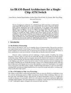
is shown below. Figure 11 shows admissible load Ladm for assuring the cell loss ratio CLR < 10−9 . Cell loss may occur when cells enter a WDM group from a basic switch† , when cells enter a speed conversion buffer at SP, and when cells enter the arbitration buffer in RP. As S exceeds C/M , Ladm becomes large as shown in Fig. 11. Ladm saturates if S is increased above the inflexion point. We call this point S0 . In the region where S is smaller than S0 , the bottleneck of Ladm is S. In this case, cell loss occurs at the speed conversion buffer. Our design policy for the proposed switching system is to increase the statistical multiplexing gain by using dynamic bandwidth sharing. Therefore, wavelength signal speed S should be fast, in order to avoid cell loss in the speed conversion buffer at SP and move the bottleneck to the other points. In the region from S0 , Ladm does not change. This is because the bottleneck of Ladm is the bandwidth of WDM group, which is C. S does not need to be fast. Note that cell loss at the speed conversion buffer may occur even in this region, but the cell loss ratio at
Fig. 11
Admissible load when S increases.
the speed conversion buffer is much smaller than the cell loss ratio when cells enter a WDM group from a basic switch. That is why Ladm does not change even if S0 increases in this region. CLR was evaluated by using the buffer-less approximation method presented in [11]. We assumed that the buffer size in the proposed switch is large enough to absorb several simultaneously arriving cells (bursty traffic) within one cell-time slot [6],[12]. For this purpose, buffer size need not be large, and the buffer-less approximation method is valid. When the peak rate of the accommodated connections becomes large, S0 increases. To implement SP and RP cost-effectively, we should design S0 to be as slow as possible under the worst traffic condition in the switching system. 5.
Conclusions
This paper proposed a 3-stage ATM switch architecture that uses optical WDM grouped links and dynamic bandwidth sharing. The proposed architecture has two features. The first feature is the use of WDM technology to make the number of cables directly proportional to system size. The second feature is the use of dynamic bandwidth sharing among WDM grouped links to hold statistical multiplexing gain constant even if switching system scale is increased. A performance evaluation has confirmed its scaleability and cost-effectiveness. The proposed architecture is scaleable in terms of the number of cables and admissible load. We showed to determine the appropriate wavelength signal speed to implement the switch in a cost-effective manner. Therefore, the proposed architecture will suit future high-speed multimedia ATM networks. † When the basic switch is an output-buffer type switch, cell loss occurs at the output buffer of the basic switch.
IEICE TRANS. ELECTRON., VOL.E82–C, NO.2 FEBRUARY 1999
218
References [1] T. Chaney, J.A. Fingerhut, M. Flucke, and J.S. Turner, “Design of a gigabit ATM switch,” Proc. IEEE INFOCOM’97, pp.2–11, 1997. [2] K. Genda and N. Yamanaka, “TORUS: Terabit-per-second ATM switching system architecture based on distributed internal speed-up ATM switch,” IEEE J. Sel. Areas Commun., vol.15, no.5, 1997. [3] J. Turner and N. Yamanaka, “Architectural choice in large scale ATM switches,” IEICE Trans. Commun., vol. E81-B, no.2, Feb. 1998. [4] Y. Kamigaki, T. Nara, S. Machida, A. Hakata, and K. Yamaguchi, “160 Gbit/s ATM switching system for public network,” Proc. IEEE GLOBECOM’96, pp.1380–1387. [5] N. Yamanaka, S. Yasukawa, E. Oki, and T. Kawamura, “OPTIMA: Tb/s ATM switching system architecture: Based on highly statistical optical WDM interconnection,” Proc. IEEE ISS’97, System Architecture, 1997. [6] K. Shiomoto and N. Yamanaka, “An admission control scheme based on measurement of instantaneous utilization,” IEICE Trans., vol.J80-B-I, no.12, pp.950–960, Dec. 1997. [7] M. Aida and T. Kubo, “Efficient cell-loss ratio estimation for real-time call admission controller for ATM networks,” IEEE/ACM Trans. Networking, vol.4, no.5, pp.758–765, 1996. [8] H.G. Perros and K.M. Elsayed, “Call admission control schemes: A review,” IEEE Commun. Mag., pp.82–91, Nov. 1996. [9] E. Oki and N. Yamanaka, “High-speed connection admission control in ATM networks by generating virtual requests for connection,” Proc. IEEE ATM’98 Workshop, pp.295– 299, May 1998. [10] H. Takahashi, K. Oda, H. Toba, and Y. Inoue, “Transmission characteristics of arrayed waveguide N × N wavelength multiplexer,” IEEE J. Lightwave Technol., vol.13, no.2, 1995. [11] T. Murase, H. Suzuki, S. Sato, and T. Takeuti, “A call admission control scheme for ATM networks using a simple quality estimate,” IEEE J. Sel. Areas Commun., vol.9, April 1991. [12] A. Baiocchi, N.B. Melazzi, M. Listani, A. Roveri, and R. Winkler, “Loss performance analysis an ATM multiplexer loaded with high-speed on-off sources,” IEEE J. Sel. Areas Commun., vol.9, no.9, pp.1461–1470, 1991. [13] T. Takahashi, H. Kataoka, and M. Hirano, “Broadbandpacket switching network featuring dynamic link speed control,” IEICE Trans.Commun., vol.E-71, no.9, 1988. [14] K. Sasayama, Y. Yamada, K. Habara, and K. Yukimatsu, “Frontiernet: Frequency-routing-type time-division interconnection network,” IEEE J. Lightwave Technol., vol.15, no.3, 1997.
Kohei Nakai received the B.E. and M.E. degrees in electronics engineering from the University of Tokyo, Japan, in 1995 and 1997, respectively. In 1997, he joined Nippon Telegraph and Telephone Corporation’s (NTT’s) Network Service Systems Laboratories, Tokyo Japan. He is currently researching high-speed ATM switching systems at NTT Network Service Systems Laboratories. He is a member of Society.
Eiji Oki received the B.E. and M.E. degrees from Keio University, Yokohama Japan, in 1991 and 1993, respectively. In 1993, he joined Nippon Telegraph and Telephone Corporation’s (NTT’s) Communication Switching Laboratories, Tokyo Japan. He is currently researching future multimedia communication network architecture based on ATM techniques, traffic control issues of ATM networks, and high-speed ATM switching system at NTT Network Service Systems Laboratories as a Research Engineer. He received IEICE Switching System Research Award in 1998. He is a member of IEEE Communication Society.
Naoaki Yamanaka was born in Sendai-city, Miyagi prefecture, Japan, on July 22, 1958. He graduated from Keio University, Japan where he received B.E., M.E. and Ph.D. degrees in engineering in 1981, 1983 and 1991, respectively. In 1983 he joined Nippon Telegraph and Telephone Corporation’s (NTT’s) Communication Switching Laboratories, Tokyo Japan, where he was engaged in research and development of a high-speed switching system and high-speed switching technologies such as ultra-high-speed switching LSI, packaging techniques and interconnection techniques for Broadband ISDN services. Since 1989, he has been active in the development of Broadband ISDN based on ATM techniques. He is now researching future ATM based broadband ISDN architecture, and traffic management and performance analysis of ATM networks. He is currently a senior research scientist, supervisor, distinguished technical member in Broadband Network System Laboratory at NTT. Dr. Yamanaka received Best of Conference Awards from the 40th and 44th IEEE Electronic Components and Technology Conference, TELECOM System Technology Prize from the Telecommunications Advancement Foundation, two times of IEICE Switching System Research Award and IEEE CPMT Transactions Part B: Best Transactions Paper Award in 1990, 1994, 1994, 1996, 1998 and 1996 respectively. Dr. Yamanaka is Broadband Network Area Editor of IEEE Communication Surveys, Associate Editor of IEICE Transaction, IEICE Communication Society International Affairs Director as well as Secretary of Asia Pacific Board at IEEE Communications Society. Dr. Yamanaka is a senior member of IEEE.