Scalable and Self-Sustained Algorithms for Femtocell Interference Mitigation Sameera Palipana1 , Yasir Zaki2 , Umar Toseef1 , Jay Chen2 , and Carmelita Goerg1 1
2
Communication Networks (ComNets), University of Bremen, Otto-Hahn-Allee NW1, 28359, Bremen, Germany. {dmsp,umr,cg}@comnets.uni-bremen.de Computer Science Department, New York University Abu Dhabi (NYUAD), UAE {
[email protected],
[email protected]}
Abstract. Cellular networks are reaching their physical limits providing capacity that is almost near the Shannon theory. However, cellular usage is still increasing exponentially with hungry applications demanding higher data rates. As a result, designers are facing significant challenge in meeting the required demands. One of the promising solutions, being fostered by the 3GPP, is to increase the spectral efficiency through higher frequency reuse using smaller and denser network cells such as femto, pico and nano cells. One of the main challenges behind using smaller cells is managing interference, in this paper, we propose two novel solutions that alleviate the interference of femto-cells on macro-cell user equipment (MUEs). The solutions do not rely on any additional information exchange or signaling, nor do they rely on the backhaul and it’s delay. The first proposal is Femto-cell Power Control Scheme (FPCS) that utilizes an analytical approach to adapt the femto base station’s transmit power based on Channel Quality Indicator (CQI) reports from affected MUEs. The second method is Random Physical Resource Block Selection Scheme (RPSS) that allocates the femto-cell’s resources from a random subset of Physical Resource Blocks (PRBs) so that the MUEs benefit from a reduced interference level. Our evaluations have shown that the two proposals do alleviate the femto-cell interference significantly, increasing the SINR and enhancing the end performance. To the best of our knowledge, no similar work exist in literature that addresses the femto-cell’s interference without information exchange. Key words: heterogeneous networks, femtocells, interference mitigation, power control, resource partition
1 Introduction Femto-cells are small, low power, low cost and plug and play cellular base stations that can be placed inside homes and small business. It can be connected to the operator’s network through Internet Protocol (IP) by means of a third party backhaul connection such as Asymmetric Digital Subscriber Line (ADSL) or through fiber optics. Femto-cells aim at providing better indoor coverage, in-
2
Sameera Palipana, Yasir Zaki, Umar Toseef, Jay Chen, and Carmelita Goerg
creasing network capacity and also providing new services to users. Accordingly, they provide higher data rates while reducing the macro-cells load. However, there are several technical challenges that must be addressed before femto-cells can coexist among other macro- and pico-cells. These challenges can be categorized into: inter-cell interference, handover in areas with multiple femto-cells, self configuration, healing and optimization, spectrum accuracy, and providing quality of service using the shared backhaul connection [1, 2]. In a heterogeneous network with femto-cells and macro-cells coexistence, the downlink inter-cell interference can occur across femto-macro tiers (cross-tier interference), as well as in femto-femto tiers (co-tier interference). The main reasons for this downlink inter-cell interference are the deployment of femtocells without proper planning, spectrum reuse or co-channel deployment by femto-cells, Closed Subscriber Group (CSG) access and uncoordinated operation among femto-cells and macro-cells [3]. Standardization bodies like 3GPP Technical Specification Group for Radio Access Networks (TSG-RAN) Work Group 4 (WG4) has also looked into interference reduction methods for LTE [4]. The methods they have proposed for the downlink data channel protection can be divided into two areas, power control and radio resource management. Radio resource management involves methods such as component carrier aggregation, almost blank subframes and PRB level resource partitioning. To overcome the downlink cross-tier interference, several power controlling schemes are proposed in the literature. [5] provides a transmit power calculation method considering the distance between the femto-cell and the most interfering macro-cell which offers a minimum coverage for its serving HUE. Yavuz et. al. [6] use a power setting based on the received signal strength from the macrocell which is measured by the Home NodeB and adjusts the transmit power to achieve a minimum quality level for the macro-cell control channel. However, in these methods there is a high probability that the femto-cell decreases its power without a MUE in the vicinity, resulting in an unnecessary performance degradation. [7] proposes a dynamic power control algorithm that uses the CQI reports from HUEs in Frequency Division Duplex (FDD) High Speed Downlink Packet Access (HSDPA) and the excellent transmission quality associated to a femto-cell to adjust the downlink power transmission according to a given targeted CQI. However, the femto-cell is restricted here to achieve a target Quality of Service (QoS) even without MUE influence. Morita et. al. [8] introduced an adaptive power level setting scheme that depends on the availability of MUEs. Here, the HeNB measures the variation of uplink received power from the MUEs and thereby, the transmit power of the femto-cell can be adjusted intelligently. This scheme requires the femto-cell to enable the Network Listen Mode (NLM) to sniff the environment as a UE. Several resource partitioning schemes are proposed in literature trying to alleviate the downlink cross-tier interference. A dynamic resource partitioning method that denies Home enhanced NodeBs (HeNBs) to access the downlink resources that are assigned to macro UEs in their vicinity was introduced by Bharucha et al. [9]. Here, the interference on most vulnerable MUEs can be ef-
Scalable and Self-Sustained Algorithms for Femtocell Interference Mitigation
3
fectively controlled at the expense of HeNB’s capacity. Nonetheless, this method requires an X2 link for backhaul communication which is delay prone. In [10] the eNodeB schedules the UEs affected by HeNBs to a special part of the spectrum such that the HeNBs map the downlink resource blocks from uplink sensing. However, the problem lies at the uplink to downlink Resource Block mapping that’s performed by the HeNB which implies that the mapping scheme must be exchanged among the cells. [11] describes a method which measures the interference of each RB at the HeNB, classifies the RBs and allocates them to the appropriate users with suitable transmit powers. This method is computationally intensive and the interference measurement is done at the HeNB and not the UE. [12] describes a scheme that uses time domain muting where the MUEs in a coverage hole are protected by scheduling them only on the muted sub-frames, but it may waste resources by scheduling macro users only on muted sub-frames. This paper puts forward two novel interference mitigation schemes: FPCS and RPSS. FPCS is an adaptive power control scheme that detects affected MUEs based on their CQI feedback utilizing the Network Listen Mode (NLM) of the femto-cell. RPSS is an efficient yet simple resource partitioning scheme which does not rely on extra signaling, measurements and estimations.
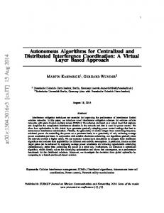
2 Interference mitigation architecture 2.1 Femto-cell Power Control Scheme (FPCS) The main idea of this scheme is to achieve a controlled femto-cell interference at a MUE depending on the CQI reported by this user. However, the reported CQI already includes the interference from the femto-cell which can be referred as “SINR with femto-cell’s interference”. Thus depending on this value, the femtocell can estimate the “SINR without its interference” at this particular MUE. Then the femto-cell can adjust its transmit power so that the SINR seen by the affected macro-cell user remains at a certain percentage of the estimated SINR without interference. This percentage is referred here as the SINR reduction factor, c. Figure 1a illustrates the functionality of this scheme. When a femto-cell is started and during the initialization process, the femtocell gathers information on its position, potential interferer positions with their transmission powers, and the wall penetration loss associated with the building it’s serving. This takes place every time the femto-cell is booted or when it is plugged in. A femto-cell belongs to a specific cellular operator and will be sold and licensed by that operator. Thus, femto-cells will be configured by the operator to exchange a set of information during the beginning of the femto-cell operations and maybe during regular intervals at the scale of hours or days. After the initialization, when the femto-cell receives a CQI report from a nearby MUE, it estimates the MUE’s SINR without the femto-cell interference, γ 0woi . Then it adjusts its transmit power depending on this γ 0woi . As a consequence, during the next transmission time interval (TTI), the femto-cell would still generate interference to the MUE, however it will be consistent with the pre-set operational limits of allowed interference. The MUE would report back
4
Sameera Palipana, Yasir Zaki, Umar Toseef, Jay Chen, and Carmelita Goerg
the new CQI to its serving macro-cell and the femto-cell would again hear this and adjust it’s transmit power accordingly. Precise location information at the initialization process of the femto-cell can be obtained from the operator using the IP address of the femto-cell through the backhaul link. Here, the operator would know the location of the femto-cell due to the ADSL or fiber optics subscription of the user. The positions and transmit powers of potential interferers is sent by the operator to the femto-cell during this process. Hence the wall penetration loss, L0ow can be estimated using the reception power of the strongest interfering macro-cell, Prx,M as follows: L0ow [dB] = Ptx,M [dB] − Prx,M [dB] − P LM,F [dB]
(1)
Where, Ptx,M is the transmit power of the strongest interfering macro-cell, Prx,M is the received power by the femto-cell from this strongest interferer, P LM,F is the path loss between this interferer and the femto-cell. We define the relationship of estimated SINR without femto-cell’s interference (γ 0woi ), SINR with femto-cell interference (γwi ) and SINR reduction factor (c) in eqn. 2. This relationship can be utilized to determine γ 0woi and as a result an expression for the femto-cell’s transmit power can be derived based on known and estimated parameters. ( 1 × γwi [dB], if γwi [dB] > 0 (2) γ 0woi [dB] = c c × γwi [dB], if γwi [dB] < 0 Here, γwi can be approximated as follows: γwi ≈
0 Prx,M 0 IM,noise + Prx,F
(3)
0 ) is the estimated received power from the macro BS at the MUE, Where, (Prx,M 0 is the esti(IM,noise ) is the interference from all other BSs + noise and Prx,F mated received power from the femto-cell at the MUE. The SINR w/o femtocell’s interference at the MUE, estimated by the femto-cell, is defined as follows:
γ 0woi =
0 Prx,M IM,noise
(4)
The femto-cell estimates the received power from the macro-cell using the macro BS’s transmit power (Ptx,M ) and the estimated path loss between the MUE and the macro-cell, (P L0M U E,M ). 0 Prx,M [dB] = Ptx,M [dB] − P L0M U E,M [dB]
(5)
Likewise, the received power from the femto-cell at the MUE is estimated using the femto BS’s transmit power (Ptx,F ), estimated path loss between the MUE and the femto-cell (P L0M U E,F ), and estimated wall penetration loss (L0ow ) as: 0 Prx,F [dB] = Ptx,F [dB] − P L0M U E,F [dB] − L0ow [dB] (6) Thus the femto-cell’s transmit power can be expressed as follows:
Scalable and Self-Sustained Algorithms for Femtocell Interference Mitigation
5
Ptx,F [dB] = P L0M U E,F [dB] + Low [dB] + Ptx,M [dB] − P L0M U E,M [dB] + f (γwi , c) − γwi [dB]
(7)
, where ( f (γwi , c) =
(1− 1 )
[1 − γwi c ][dB] if γwi [dB] > 0 (1−c) [1 − γwi ][dB] if γwi [dB] < 0
Next, we are going to describe each of the assumptions taken by the FPCS and how these assumptions can be justified. Affected MUE Detection: A femto-cell can listen to CQI signals of macro UEs in its vicinity through the NLM mode, since users are sending these CQI reports in the uplink to their connected macro-cell. The femto-cell also belongs to the same operator, thus it can be configured to listen to the CQIs from these users. A femto-cell is capable of listening to the uplink transmissions of only nearby macro users because the signal power tends to decrease as the user goes further away. Therefore the femto-cell can identify which users are in its vicinity. Moreover, a femto-cell determines if a MUE is affected by the HeNB interference when the CQI values reported by this user tend to drop for a certain duration. MUE Position Estimation: It is necessary to estimate the affected MUE’s position by the femto-cell for FPCS to function properly. To determine the transmit power that achieves the estimated SINR at the MUE, it is required to estimate the path loss of the MUE-femtocell and MUE-macrocell links according to eqn. 7. The femto-cell estimates the affected UE’s path loss by behaving as a MUE and performing uplink power control. Accordingly, uplink reception power from the femto-cell and the MUE will be the same at the macro-cell at this instance. Hence the path loss between the femto-cell and the MUE can be estimated using the femto-cell uplink transmit power, Ptx,F,U L and the femto-cell uplink reception power Prx,F,U L as follows: 1 (Ptx,F,U L − Prx,F,U L ) − L0ow (8) 2 Figure 1b further illustrates the MUE’s path loss estimation by the femto-cell. However, the influence of fading is not considered for the path loss estimation because the femto-cell is not aware of the amount of fading present at the MUE. Fading is a property that is inherent to the MUE depending on its signal propagation, thus the femto-cell is unable to acquire any information on this. P L0M U E,F =
2.2 Random PRB Selection Scheme (RPSS) Unlike FPCS, this scheme performs interference mitigation exploiting resource partitioning. In OFDMA, downlink resource allocation is characterized by scheduling UEs with Physical Resource Blocks (PRBs) and each resource block is assigned only to one UE at a time. In assigning PRBs to users, usually the best PRBs having the highest SINR are allocated to achieve a higher Modulation and Coding Scheme (MCS), a higher data rate and spectral efficiency. In this scheme, downlink resource partitioning is performed as follows: The femto-cell chooses
6
Sameera Palipana, Yasir Zaki, Umar Toseef, Jay Chen, and Carmelita Goerg
PRBs for a subset, pi in the ith interval such that pi ⊆ S, where S is the set of all PRBs. PRBs for this subset are chosen randomly. The chosen PRBs are used for a predetermined time, i.e. a pre-defined number of TTIs (NT T I ) to schedule the HUEs. They are released when the usage duration of the ith interval (ti ), ti ≥ NT T I , to choose the next set of PRBs (pi+1 ) for the next interval, i + 1. The optimum size of the subset, p and the optimum usage duration of these chosen PRBs, NT T I are determined using a sensitivity analysis. Essentially, this optimum combination is required to reduce the interference efficiently at the MUEs while satisfying the HUEs’ data rate and Quality of Service (QoS) demands. Figure 1c further elaborates the RPSS algorithm. Rx Power [dB]
Initialize
Ptx, F, UL
MUE uplink tx
𝑇𝑇𝐼𝑖+1
Affected MUE calculates CQI or EESM
Initialization
𝑇𝑇𝐼0
Femtocell receives EESM (𝛾𝑊𝐼 ) from the affected MUE
𝑇𝑇𝐼𝑖
Femtocell estimates SINR without its interference(𝛾𝑊𝑂𝐼 )
Low PLMUE, F +Low
Ptx, MUE
Low PLMUE, F +Low
Prx, M, UL Prx, F, UL
Femtocell adjusts its tx power (𝑃𝑡𝑥,𝐹 )
Distance from MUE
𝑇𝑇𝐼𝑖
(a) FPCS block diagram
𝑇𝑇𝐼𝑖
𝑖 =𝑖+1
Select PRBs 𝒕𝒊
yes Check 𝒕𝒊 >𝑵𝑻𝑻𝑰
HeNB
Interference
- Select a size for 𝒑 - Select 𝑵𝑻𝑻𝑰
eNodeB
MUE
HUE
(b) MUE position estimation
(c) RPSS algorithm
Fig. 1: Proposed algorithms Moreover, this scheme does not guarantee that the chosen subset will not interfere with other macro users in the vicinity. Since the subsets are chosen randomly, there is still a probability that it might be the same PRBs that the MUE in the vicinity is using. Nonetheless, the idea is to have a simple solution that does not require any prior knowledge, assumptions or any complexity. Comparison of FPCS and RPSS: As both FPCS and RPSS do not rely on backhaul communication, they can perform without substantial delays. In FPCS, the femto-cell has control over interference that it generates at the macro UE. The assumptions that are made for this scheme are reasonable, following the 3GPP specifications. Another advantage of this scheme is that interference mitigation is performed based on the channel condition at the macro user, not the femto-cell. In contrast, RPSS has the advantage of simplicity, it does not rely on signaling, measurements, or assumptions. In spite of that, the parameters for PRB subset and duration must be chosen carefully so that both MUEs and HUEs benefit from a balanced performance.
3 Channel model There are three path loss models used in this work according to [13] which are used conditional to the type of link that exists between a transmitter and a receiver. Expression 9 is used as the path loss model for an outdoor link (useful or interfering) between a macro-cell and a MUE.
Scalable and Self-Sustained Algorithms for Femtocell Interference Mitigation
P L1 [dB] = 15.3 + 37.6log10 R
7
(9)
Where, R is the distance between the UE and the macro-cell. Expression 10 is used for a HUE that’s served by a HeNB in the same house P L2 [dB] = 38.46 + 20log10 R
(10)
Finally, equation 11 is used for a MUE which is situated outside a house but receiving signals from a HeNB P L3 [dB]
=
max(15.3 + 37.6log10 R, 38.46 + 20log10 R) + Low
(11)
Where, Low is the wall penetration loss. All links are modeled with shadow fading using Log-Normal distribution with spatial correlation according to [14]. The fast fading model used in this work is a Jakes’-like model [15][16]. Hence the fast fading attenuation depends on both time and frequency as it considers delay spread for frequency selectivity and Doppler spread for time selectivity. Mobility of the users prompts Doppler spread. The power delay profile caused by multi-path propagation which is the reason behind frequency selectivity is modeled using the ITU Pedestrian B channel specification [17]. This is a commonly used medium delay empirical channel model for office environments. Unlike path loss and slow fading, fast fading is different for each PRB of each user since the channel is frequency selective.
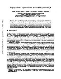
4 Simulation and Results This section explains the simulation environment of this work e.g. simulator, user mobility, simulation parameters and evaluates the performance of the two interference mitigation schemes introduced in the previous sections. 4.1 ComNets LTE-A System Level Simulator Simulations for this work are carried out using ComNets LTE-A system level simulator [18] [19] [20] in OPNET modeler software. Figure 2a illustrates a scenario obtained from the project editor of the simulator. There are modules for Application, Application Profile, Global UE List, Remote Server, Access Gateway (aGW), Routers, macro-cells, femto-cells and UEs. The module, Application is used to define and configure applications of the UEs. The module, Profile defines and configures traffic models such as simulation operation modes, start time, simulation duration and repeatability for different applications. Remote Server is the remote application server and aGW is used to route and forward data packets between the remote server and the radio access network. IP based routers are deployed in the transport network. Global UE List gathers users’ and eNodeB’s information, collects SNR of each user and manages the mobility of each user in each TTI. The cells schedule their UEs using Optimized Service Aware Scheduler (OSA) [21] [22] in this simulator. The OSA scheduler differentiates between different QoS classes mainly by defining several MAC QoS bearer types such as Guaranteed (GBR) and non-Guaranteed (nonGBR) Bit Rate. At the same time, it gains
8
Sameera Palipana, Yasir Zaki, Umar Toseef, Jay Chen, and Carmelita Goerg
from the multi-users-diversity by exploiting the different users’ channel conditions in order to maximize the cell throughput in a proportional fair manner. As mentioned in section 3 the shadow fading maps and the fast fading model for femto- and macro-cell UEs were produced using open source Vienna Simulator [23] and they were deployed in ComNets LTE-A System Level Simulator. Separate shadow fading maps with sizes of 2400m×2080m and 100m×100m were generated for both femto- and macro-cells respectively. Table 1 illustrates the used parameters to generate these maps and these are specified in [13]. Mean Standard deviation Correlation distance
Macro-cell Femto-cell 0dB 0dB 8dB 4dB 50m 3m
Table 1: Parameters of Shadow fading maps of macro-cells and femto-cells 4.2 Mobility model HUEs and MUEs have two different mobility models. MUEs travel inside the coverage area of the macro-cell that it is connected to. HUEs on the other hand travel inside a 15m×15m building. Once the HUE reaches a wall, they choose a random direction to traverse inside that same building. A femto-cell can accompany several HUEs inside the building. MUEs do not enter the house and they also do not change their direction once they come across a wall of a house on their way. This is done to avoid the extreme interference they have to confront inside houses with femto-cells. This implies that when a MUE from outside enters a house, it joins the Closed Subscriber Group of that house and hence the HeNB doesn’t behave as an interference source. Macro-cells do not serve any of the HUEs placed in their respective coverage areas, and HUEs are only served through the femto-cells. Figure 2b illustrates the mobility of a femto and a macro user having the above mentioned behavior. In figure 2b the red line marks the macro-cell coverage boundary, the 100m×100m yellow rectangle represents the femto-cell interference area and the light blue rectangle represents the femto-cell coverage area. The difference of the femto-cell coverage area and the interference area is that femto-cells do not serve any users beyond their coverage although the MUEs can receive their power as interference. 4.3 Simulation parameters Table 2a summarizes the simulation assumptions and general parameters used within the evaluation. There are three users classified according to the type of application used by them: FTP, VoIP and Video. Table 2b summarizes the configuration parameters of those applications. Femto-cells in the simulations are placed inside small indoor apartments and the apartments are modeled with an area of 15m×15m. The walls of the apartments are modeled to have a 20 dB wall penetration loss. Femto-cells and their apartments are placed only in the center cell, where four apartments are considered for the evaluation and are placed within the micro-cell. Inside each apartment there is a femto-cell and a HUE. Each apartment is 150m away from the center cell. Parameter ‘Command Mix’ in table 2b denotes the percentage of FTP downloads to FTP uploads. Hence a Command Mix of 100% means that the application performs only FTP downloads. The Inter-request time denotes the time
Scalable and Self-Sustained Algorithms for Femtocell Interference Mitigation
9
taken for the next file request to start once a file download is completed. Request for the next file download is sent only after the current download is finished. The simulator consists of eight types of quality of service classes and each class has a different QoS characteristic and this means that each has different priority over the air interface. The types of quality of service classes arranged in the order of lowest to highest priority are: Best Effort, Background, Standard, Excellent Effort, Streaming Multimedia, Interactive Multimedia, Interactive Voice and Reserved. VoIP application’s data rate for the encoder scheme GSM EFR is 12.2 kbps and it belongs to the Adaptive Multi-Rate codecs family which is an audio data compression scheme optimized for speech coding. The Type of Service (TOS) is configured as ‘EF’ which corresponds to Interactive Multimedia traffic. Video users are configured with a Frame inter-arrival time of 15 frames/s and a Frame size of 2133 Bytes contribute to a bit rate of 256 kbps. Type of Service of Video is ‘AF31’ which corresponds to quality of service class Excellent Effort. All the femto-cell users are configured as Video users with a bit rate of 18Mbps to enable maximum interference to the MUEs.
(a) A simulation scenario
(b) Mobility Model
Fig. 2: Simulation Environment Parameter Value Downlink operating frequency 2.0 GHz Number of cells 7 Inter eNodeB distance 500m MUEs in the center cell 10 MUEs in each surrounding cell 5 Apartment size 15 × 15 m2 Femto-cells in the center cell 4 HUEs per femto-cell 1 Femto-cell distance to macro-cell 150m Total number of PRBs 25 eNodeB transmit power per PRB -4 dBm Femto-cell’s total transmit power 0 dBm (without power control) Noise per PRB -120.447 dBm Noise floor 9 dB Wall penetration loss 20 dB UE speed 3 kmph (a) Simulation parameters
User Parameter Command Mix (Get/Total) FTP Inter-request Time (seconds) Type of Service File Size Encoder Scheme Voice Frames per Packet VoIP Type of Service Traffic mix (%) Conversation environment Frame inter-arrival time Video Frame size Type of Service Traffic mix (b) Traffic model parameters
Table 2: Simulation parameters
Value 100% 1 Best Effort 1 MB GSM EFR 1 AF33 All discrete Land phone (Quiet room) 15 frames/s 2133 Bytes EF All discrete
10
Sameera Palipana, Yasir Zaki, Umar Toseef, Jay Chen, and Carmelita Goerg
4.4 Results and Analysis In this section, we present the simulation results for our evaluations. The purpose of these evaluations is to study and compare the effects of the two interference mitigation schemes proposed in this paper: FPCS and RPSS. The performance of FPCS is examined using three scenarios with SINR reduction factor, c = 95%, 90% and 85%. These percentages reflect the amount of SINR reduction that is expected at the macro UE due to the presence of the femto-cell. The results of the three FPCS scenarios are compared with the results of RPSS. Two reference scenarios are used with worse and best situations, these are: a scenario with no femto-cell interference ‘No HeNB’ which is the ideal situation, and a scenario having maximum interference from the femto-cells with fixed transmit power, ’Fixed’ which is the worst possible situation. There are altogether six scenarios compared and they are listed in table 3. Ten simulations are performed with ten different seeds for each scenario. The confidence interval calculations in all the result graphs are carried out using Student’s t distribution. The types of collected results from the above mentioned six scenarios are as follows: for FTP users the SINRs and the download response times are compared during the interference periods from HeNBs. For VoIP users, the Mean Opinion Scores (MOS), end-to-end delays and SINRs are compared. Finally for Video users the end-to-end delays and SINRs are compared. MOS measures the subjective quality of a voice call and returns a scalar one digit score to express the quality of the call [20]. The MOS values range from 1 to 5, with 5 being the best quality and 1 the worst quality. MOS values are dependent on the end-to-end delays and jitter of the delay of VoIP users. Scenario Term FPCS: 95% SINR reduction ‘95%’ FPCS: 90% SINR reduction ‘90%’ FPCS: 85% SINR reduction ‘85%’ RPSS ‘Random’ No interference from femto-cells ‘No HeNB’ Femto-cells with fixed transmit power ‘Fixed’
Table 3: Types of scenarios used in the simulations and used terms Figure 3a illustrates the SINR of VoIP users, figures 3b and 3c depict the performances of their applications in terms of end-to-end delay and MOS. In the SINR comparisons of ‘95%’, ‘90%’ and ‘85%’ against the ‘Fixed’ scenario, the three power control scenarios of FPCS have outperformed the ’Fixed’ one with gain margin ranging from 30.52% - 42.75%. This shows a clear improvement over the worst case scenario. This demonstrates the ability of FPCS to mitigate the femto-cell interference. However, RPSS shows the best performance with the exception being that they achieve much lower data rates for the HUEs. VoIP is an example for a GBR real time application that is sensitive to delays. Usually an end-to-end delay of more than 150 ms for a VoIP application results in bad call quality [20] and deteriorates user satisfaction. The significant fact is that the two interference mitigation schemes show values less than 150 ms, while the ’Fixed’ scenario shows that MUE is having very bad call quality which is much higher than 150 ms. This indicates the performance enhancement in the VoIP
Scalable and Self-Sustained Algorithms for Femtocell Interference Mitigation
End−to−end delay (s)
SINR (dB)
5
0.4
10 8 6 4
4
0.3 MOS
12
0.2
0
No Random95% 90% 85% Fixed HeNB
(a) VoIP mean SINR
3 2
0.1
1
2 0
11
0
No Random95% 90% 85% Fixed HeNB
(b) VoIP mean delays
No Random 95% 90% 85% Fixed HeNB
(c) VoIP mean MOS
Fig. 3: Results comparison of VoIP users for ‘No HeNB’, ‘Random’, ‘95%’, ‘90%’,‘85%’ and ’Fixed’ scenarios application of the macro users due to the interference alleviation. MOS values depend on the end-to-end delays and the delay jitter of VoIP users. Hence MOS is also an important metric on the performance of the VoIP application. Any improvement of SINR at the macro UEs due to mitigation of interference should finally reflect on the performance of the user’s application. MOS values give an indication on the performance enhancement of the VoIP application under the two interference mitigation schemes over ’Fixed’ scenario. 12
10 Download response time (s)
10
SINR (dB)
8 6 4 2 0
No Random 95% HeNB
90%
85% Fixed
(a) Mean SINR
8 6 4 2 0
No Random 95% HeNB
90%
85% Fixed
(b) Mean response times
Fig. 4: Results comparison of FTP users for ‘No HeNB’, ‘Random’, ‘95%’, ‘90%’,‘85%’ and ’Fixed’ scenarios Figure 4a depicts the mean SINRs of FTP users for the six scenarios. Here RPSS achieves a gain margin of 38.92%, whereas FPCS with sensitivities of ‘95%’, ‘90%’ and ‘85%’ achieve 32%, 23.19% and 17.94% respectively compared to ‘Fixed’. This clearly shows that the two interference mitigation schemes perform better compared to the ‘Fixed’ scenario in terms of SINR for FTP users. Non-GBR bearers usually carry non real time or best effort type of services; FTP is an example for such a service. Hence FTP does not have high delay requirements in contrast to real time or GBR services. Figure 4b depicts the mean download response times of FTP users across the six scenarios. As expected, the download response time of the ’Fixed’ scenario has the highest delay with 8.31s FPCS and RPSS scenarios all have better download response times showing a clear edge over the worst case user application performance. Figure 5a depicts the Video users’ mean SINRs for the compared six scenarios. FPCS with sensitivities of ‘95%’, ‘90%’ and ‘85%’ achieve gain margins of 28.34%, 19.37% and 13.59% respectively and RPSS achieves a gain margin
12
Sameera Palipana, Yasir Zaki, Umar Toseef, Jay Chen, and Carmelita Goerg
12
12
10
10
8
8
SINR (dB)
SINR (dB)
of 43.24% compared to ‘Fixed’. This shows that the two interference mitigation schemes perform better compared to ‘Fixed’ in terms of SINR for Video users. Figure 5b shows the mean end-to-end delays of video users. ’Fixed’ scheme has the highest delay of about one second and the confidence interval is also high suggesting a higher variation of delays. The mean end-to-end delays for all other scenarios are less than 0.2s with a much lower delay variation suggesting a clear improvement over ‘Fixed’. This shows how the worst case scenario’s video performance is affected, emphasizing the importance of the interference mitigation. However, in all of the above SINR comparisons of VoIP, FTP and Video users, FPCS does not perform interference mitigation optimally. RPSS out performs FPCS in all the scenarios. This can be attributed to the amount of fading prevalent at the macro UEs which is not estimated by the femto-cell during the interference mitigation process in FPCS.
6 4 2 0
6 4 2
No Random95% 90% 85% Fixed HeNB
(a) Mean SINR
0
No Random95% 90% 85% Fixed HeNB
(b) Mean delays
Fig. 5: Results comparison of Video users for ‘No HeNB’, ‘Random’, ‘95%’, ‘90%’,‘85%’ and ’Fixed’ scenarios
(a) Mean SINR
(b) Mean delays
Fig. 6: Comparison of HUEs for ’95%’, ’90%’,’85%’ and ’Random’ scenarios Figures 6a and 6b represent respectively the number of used PRBs and the throughputs of the four HUEs. It can be observed that the number of PRBs and throughputs of RPSS are much less than the other three in all scenarios. The other significant fact is the throughputs and the number of used PRBs of FPCS have similar values in all three. Hence it is evident that the performance of HUEs are limited in RPSS due to the limited number of PRBs. On the other hand the FPCS provides a much balanced scheme that mitigates macro UE interference successfully while being able to provide a better service to femto-cell users.
Scalable and Self-Sustained Algorithms for Femtocell Interference Mitigation
13
5 Conclusion In this paper, two novel interference mitigation schemes are proposed and evaluated, mainly: FPCS with ‘95%’,‘90%’ and ‘85%’ SINR reduction and RPSS. Results of these two schemes were compared against an ideal case, ‘No HeNB’, where there is no interference from femto-cells, and a worst case where there is maximum interference from femto-cells, ‘Fixed’. The macro users were configured with three types of applications, VoIP, video and FTP and their performance was evaluated under the two interference mitigation schemes. The results have shown that as the SINR of the macro users improve, performance of the user applications have also improved compared to the worst case situation. Our results show that the two interference mitigation schemes perform efficiently compared to the worst case situation. Although RPSS performs better than FPCS with regards to MUE SINR and the users’ applications performance, the femto-cell users suffer because only a subset of PRBs is allocated to their users. In addition, in real life situations the cells can become increasingly loaded with MUEs and as a result when choosing a subset of PRBs, there might still be a high probability that this subset would interfere with certain MUEs. On the other hand, FPCS gives a balanced performance between the performance of the MUEs and the HUEs, creating a fair trade off between the two. It efficiently alleviates the femto-cell’s interference on MUEs while providing a good service to the HeNB users. The main issue with FPCS is, as it’s not able to estimate the amount of fading at the MUEs, the efficiency of interference mitigation decreases. This has to be further studied and a solution on how to estimated these additional effects and deal with these situations must be devised. The two interference mitigation schemes have several novel features compared to the current state of the art with regards to simplicity, lower hardware intensiveness and non-reliance on backhaul communication. As mentioned earlier, most state of the art solutions focus on in-band or out-of band signaling with high information exchange, but our schemes do not require any of this signaling, which is a major plus since signaling would cause overhead on and has delay implications. The FPCS in particular has more control over the amount of interference it should generate at the macro UE due to its analytical approach. As this method relies on UE measurements, it is also capable of dynamically adapting to the changing interference conditions at random places. Comparatively the RPSS is a much simpler approach which provides very efficient interference mitigation with only a slight reduction of performance at the femto-cell users.
References 1. D. Lopez-Perez, A. Valcarce, G. de la Roche, and J. Zhang, “OFDMA femtocells: A roadmap on interference avoidance,” Communications Magazine, IEEE, 2009. 2. D. Lopez-Perez, I. Guvenc, G. de la Roche, M. Kountouris, T. Quek, and J. Zhang, “Enhanced intercell interference coordination challenges in heterogeneous networks,” Wireless Communications, IEEE, 2011.
14
Sameera Palipana, Yasir Zaki, Umar Toseef, Jay Chen, and Carmelita Goerg
3. H. Burchardt, Z. Bharucha, and H. Haas, “Distributed and autonomous resource allocation for femto-cellular networks,” in Signals, Systems and Computers, 2012 Conference Record of the Forty Sixth Asilomar Conference on, 2012. 4. 3GPP TR 36.921, “ FDD Home eNode B (HeNB) Radio Frequency (RF) requirements analysis (Rel. 10),” 3GPP, Tech. Rep., 2011. 5. H. Claussen, L. T. W. Ho, and L. Samuel, “Self-optimization of coverage for femtocell deployments,” in Wireless Telecommunications Symposium,, 2008. 6. M. Yavuz, F. Meshkati, S. Nanda, A. Pokhariyal, N. Johnson, B. Raghothaman, and A. Richardson, “Interference management and performance analysis of UMTS/HSPA+ femtocells,” Communications Magazine, IEEE, 2009. 7. M. Lalam, I. Papathanasiou, M. Maqbool, and T. Lestable, “Adaptive downlink power control for HSDPA femtocells,” in Future Network Mobile Summit, 2011. 8. M. Morita, Y. Matsunaga, and K. Hamabe, “Adaptive power level setting of femtocell base stations for mitigating interference with macrocells,” in VTC Fall, 2010. 9. Z. Bharucha, A. Saul, G. Auer, and H. Haas, “Dynamic resource partitioning for downlink femto-to-macro-cell interference avoidance,” EURASIP J. Wirel. Commun. Netw., 2010. 10. I. Guvenc, M.-R. Jeong, M. Sahin, H. Xu, and F. Watanabe, “Interference avoidance in 3GPP femtocell networks using resource partitioning and sensing,” in PIMRC Workshops, 2010 IEEE 21st International Symposium on, 2010. 11. R. Mahapatra and E. Strinati, “Radio resource management in femtocell downlink exploiting location information,” in ANTS 2011, 2011. 12. Y. Wang, K. Pedersen, and F. Frederiksen, “Detection and protection of macrousers in dominant area of co-channel CSG cells,” in VTC 2012, 2012. 13. 3GPP R4-092042, “Simulation assumptions and parameters for FDD HeNB RF requirement,” 3GPP, Tech. Rep., 2009. 14. H. Claussen, “Efficient modelling of channel maps with correlated shadow fading in mobile radio systems,” in PIMRC 2005, 2005. 15. H. S. Lichte and S. Valentin, “Implementing mac protocols for cooperative relaying: A compiler-assisted approach,” in Proceedings of SIMUTools 2008, Networks and Systems & Workshops, 2008. 16. A. K¨ opke, M. Swigulski, K. Wessel, D. Willkomm, P. T. K. Haneveld, T. E. V. Parker, O. W. Visser, H. S. Lichte, and S. Valentin, “Simulating wireless and mobile networks in OMNeT++ the MiXiM Vision,” in SIMUTools 2008, 2008. 17. ITU-R Recommendation M.1225, “Guidelines for evaluation of radio transmission technologies for IMT-2000,” ITU, Tech. Rep., 1997. 18. N. Zahariev, Y. Zaki, X. Li, C. Goerg, T. Weerawardane, and A. Timm-Giel, “Optimized Service Aware LTE MAC Scheduler with Comparison Against Other Well Known Schedulers,” in Proceedings of WWIC 2012, 2012. 19. Y. Zaki, T. Weerawardane, C. G¨ org, and A. Timm-Giel, “Long term evolution (LTE) model development within OPNET simulation environment,” in OPNETWORK 2011, 2011. 20. Y. Zaki, “Future mobile communications: LTE optimization and mobile network virtualization,” Ph.D. dissertation, University of Bremen, 2012. 21. Y. Zaki, N. Zahariev, T. Weerawardane, C. G¨ org, and A. Timm-Giel, “Optimized service aware LTE MAC scheduler: Design, implementation and performance evaluation,” in OPNETWORK 2011, 2011. 22. Y. Zaki, T. Weerawardane, C. Gorg, and A. Timm-Giel, “Multi-QoS-Aware Fair Scheduling for LTE,” in VTC 2011, 2011. 23. J. Ikuno, M. Wrulich, and M. Rupp, “System level simulation of LTE networks,” in VTC 2010, 2010.