Scalable Distributed Concolic Testing: a Case Study on a Flash Storage Platform ⋆ Yunho Kim1 , Moonzoo Kim1 , and Nam Dang1 CS Dept. KAIST Daejeon, South Korea
[email protected] [email protected] [email protected]
Abstract. Flash memory has become a virtually indispensable component for mobile devices in today’s information society. However, conventional testing methods often fail to detect hidden bugs in flash file systems due to the difficulties involved in creating effective test cases. In contrast, the approach of model checking guarantees a complete analysis, but only on a limited scale. In the previous work, the authors applied concolic testing to the multi-sector read operation of a Samsung flash storage platform as a trade-off between the aforementioned two methods. This paper describes our continuing efforts to develop an effective and efficient verification framework for flash file systems. We developed a scalable distributed concolic algorithm that utilizes a large number of computing nodes. This new concolic algorithm can alleviate the limitations of the concolic approach caused by heavy computational cost. We applied the distributed concolic technique to the multi-sector read operation of a Samsung flash storage platform and compared the empirical results with results obtained with the original concolic algorithm.
1
Introduction
On the strengths of characteristics such as low power consumption and strong resistance to physical shock, flash memory has become a crucial component for mobile devices. Accordingly, in order for mobile devices to operate successfully, it is imperative that the flash storage platform software (e.g., file system, flash translation layer, and low-level device driver) operates correctly. However, conventional testing methods often fail to detect hidden bugs in flash storage platform software, since it is difficult to create effective test cases (i.e., test cases that provide a check of all possible execution scenarios generated from complex flash storage platform software). Thus, the current industrial practice of manual testing does not achieve high reliability or provide costeffective testing. As another testing approach, randomized testing can save human effort ⋆
This work was supported by the Engineering Research Center of Excellence Program of Korea Ministry of Education, Science and Technology(MEST)/National Research Foundation of Korea(NRF) (Grant 2010-0001727) and the MKE(Ministry of Knowledge Economy), Korea, under the ITRC(Information Technology Research Center) support program supervised by NIPA(National IT Industry Promotion Agency) (NIPA-2010-(C1090-1031-0001)).
for test case generation. However, it does not achieve high reliability, because random input data does not necessarily guarantee high coverage of a target program. These deficiencies of conventional testing incur significant overhead to manufacturers. In spite of the importance of flash memory, however, little research work has been conducted to formally analyze flash storage platforms. In addition, most of such work [12, 9] has focused on the specifications of file system design, not real implementation.
In the previous work [14], the authors applied concolic (CONCrete + symbOLIC) testing [17, 10, 7] (also known as dynamic symbolic execution [18] or automated whitebox fuzzing [11]) to the multi-sector read operation (MSR) of the Samsung OneNAND flash storage platform [3] and tested all possible execution paths in an automatic and exhaustive manner. We used CREST [6] (an open source concolic testing tool for C) in the experiments and confirmed that concolic testing was effective to detect bugs. However, CREST consumed a large amount of time to analyze all possible execution paths, which is not acceptable in an industrial setting. For example, it took more than three hours to test a MSR with a small explicit environment consisting of 5 physical units and 6 logical sectors, which generated 2.8 × 10⁶ test cases in total. Although concolic testing effectively detects bugs through the full path coverage, the required heavy computational cost prohibits the use of concolic testing in real world applications.
This paper describes our continuing efforts to develop an effective and efficient verification framework for flash file systems by alleviating the limitations caused by heavy computational cost. One solution is to develop a scalable distributed concolic algorithm that can utilize a large number of computing nodes with high efficiency. Thus far, most of automated formal verification techniques such as model checking have suffered heavy computational costs. Consequently, this heavy overhead often prevents practitioners from adopting these valuable techniques. The concolic approach is a suitable technique to exploit the benefits of parallel computing. We modified the original concolic algorithm to utilize multiple computing nodes in a distributed manner so as to reduce time cost significantly. In addition, this distributed concolic algorithm is scalable to utilize a large number of computing nodes, achieving linear speedup with an increasing number of computing nodes. We applied this distributed concolic technique on the multi-sector read operation (MSR) of a Samsung flash storage platform with 16 computing nodes. This paper reports experimental results obtained with the new concolic approach and compares them with the results derived with the original concolic algorithm to demonstrate the former’s performance gain and scalability.
The organization of this paper is as follows. Section 2 explains the original concolic testing algorithm. Section 3 describes the distributed concolic algorithm. Section 4 overviews the multisector-read (MSR) function of the Samsung flash storage platform. Section 5 presents the experimental results obtained by applying the distributed concolic algorithm to MSR. Section 6 concludes the paper along with directions for future work.
2
Original Concolic Testing Algorithm
This section presents the original concolic testing algorithm [17, 10, 7]. Concolic testing executes a target program both concretely and symbolically [16, 19] at the same time. Concolic testing proceeds via the following five steps: 1. Instrumentation A target C program is statically instrumented with probes, which record symbolic path conditions (PCs) from a concrete execution path when the target program is executed. Note that PCs correspond to conditional statements (i.e., if) in the target program. 2. Concrete execution The instrumented C program is executed with given input values and the concrete execution part of the concolic execution constitutes the normal execution of the program. For the first execution of the target program, the initial inputs are assigned with random values. For the second execution and onward, input values are obtained from step 5. 3. Obtaining a symbolic path formula ϕi The symbolic execution part of the concolic execution collects symbolic path conditions over the symbolic input values at each branch point encountered along the concrete execution path. Whenever each statement s of the target program is executed, a corresponding probe inserted at s updates the symbolic map of symbolic variables if s is an assignment statement, or collects a corresponding symbolic path condition pc, if s is a branch statement. Thus, a complete symbolic path formula ϕi of the ith execution is the conjunction of all PCs pc1 , pc2 , ...pcn where pcj is executed earlier than pcj+1 for all 1 ≤ j < n. 4. Generating a symbolic path formula ϕ′i for the next input values Given a symbolic path formula ϕi obtained in Step 3, to obtain the next input values, ϕ′i is generated by negating the path condition pcj (initially j = n) and removing the subsequent PC (i.e., pcj+1 , ...pcn ) of ϕi . If ϕ′i is unsatisfiable, another path condition pcj−1 is negated and the subsequent PCs are removed, until a satisfiable path formula is found. If there are no further available new paths, the algorithm terminates. 5. Selecting the next input values A constraint solver such as a Satisfiability Modulo Theory (SMT) solver [4] generates a model that satisfies ϕ′i . This model decides concrete next input values and the entire concolic testing procedure iterates from Step 2 again with these input values. Algorithm 1 describes the original concolic algorithm in detail, which corresponds to Step 2 to Step 5. Algorithm 1 negates all PCs of a given path one by one in descending order (see line 3 to line 13) and new paths (path′ in line 9) are analyzed recursively (see line 10). To prevent redundant analysis of a given path, subsequent recursive Concolic() negates PCs of path′ up to neg limit th PC (i.e., only pc|path′ | , pc|path′ |−1 , ..., pc|neg limit| of path′ are negated one by one). Note that this concolic algorithm operates in a similar manner to the depth first order (DFS) traversal of the execution tree of a target program.
Input: path: a sequence of PCs executed in the previous execution neg limit: a position of a PC in path beyond which PCs should not be negated Output: a set of generated test cases (i.e., I’s of line 7) 1 2 3 4 5 6 7 8 9 10 11 12 13 14
Concolic(path, neg limit) { j =| path | ; while j >= neg limit do // ϕ is a symbolic path formula of path // pck is kth path condition of path and pc1 is executed first ϕ = pc1 ∧ ... ∧ pcj−1 ∧ ¬pcj ; I = SM T Solver(ϕ) // returns NULL if ϕ is unsatisfiable if I is not NULL then path′ = execute a target program on I ; Concolic(path′ , j + 1); end j = j − 1; end }
Algorithm 1: Original concolic algorithm
3
Distributed Concolic Algorithm
This section describes a distributed concolic algorithm that can utilize a large number of computing nodes. The main concept underlying the new algorithm is based on the feature that symbolic path formulas in the loop (line 3 to line 13 of Algorithm 1) of the original concolic algorithm are analyzed independently. Therefore, in order to analyze these symbolic path formulas in a distributed manner, Algorithm 2 generates and stores symbolic path formulas in queuepf (line 15) without analyzing these symbolic path formulas recursively (line 10 of Algorithm 1). If queuepf is empty (exiting the loop of line 5 to line 25) and there are no more paths to analyze in all distributed nodes, the algorithm terminates (line 31). Otherwise, the current node requests a symbolic path formula from another node n′ (line 27) and receives a symbolic path formula from n′ (line 28). The received symbolic path formula is then added into queuepf (line 29) and the algorithm continues from line 5 again. If the current node receives a request for symbolic path formulas (line 17), it sends one from queuepf (lines 19 and 20) immediately as long as queuepf is not empty. 1 Note that communication between nodes occurs only when queuepf is empty. Since queuepf is non-empty for most of the analysis time, the number of communications is small compared to the number of analyzed symbolic path formulas. In addition, the communicated message contains only one symbolic path formula, whose size is small (proportional to the length of the corresponding execution path). Furthermore, this algorithm is not affected by the complexity and/or characteristics of a target program. 1
In a real implementation, there is a server to coordinate communications between computing nodes; this is not described in this paper for the sake of providing a simple description.
Input: orig path: a sequence of PCs executed in the previous execution Output: a set of generated test cases (i.e., I’s of line 12) 1 2 3 4 5 6 7 8 9 10 11 12 13 14 15 16 17 18 19 20 21 22 23 24 25 26 27 28 29 30 31 32
DstrConcolic(orig path) { queuepf = ∅; // queue containing symbolic path formulas Add (orig path, 1) to queuepf ; repeat while queuepf is not empty do Remove (path, neg limit) from queuepf ; j =| path |; while j >= neg limit do // ϕ is a symbolic path formula of path // pck is kth path condition of path and pc1 is executed first ϕ = pc1 ∧ ... ∧ pcj−1 ∧ ¬pcj ; I = SM T Solver(ϕ); // returns NULL if ϕ is unsatisfiable if I is not NULL then path′ = execute the target program on I; Add (path′ , j + 1) to queuepf ; end if there is a request for a symbolic path formula from other node n then if queuepf is not empty then Remove (path′′ , neg limit′′ ) from queuepf ; Send (path′′ , neg limit′′ ) to n; end end j = j − 1; end end if there are uncovered paths in any distributed node then Send a request for a symbolic path formula to n′ whose queuepf is not empty; Receive (path, neg limit) from n′ ; Add (path, neg limit) to queuepf ; end until all execution paths are covered; }
Algorithm 2: Distributed concolic algorithm
Therefore, Algorithm 2 is scalable to utilize a large number of computing nodes without performance degradation.
4
Overview of Multi-sector Read Operation
Unified storage platform (USP) is a software solution to operate a Samsung flash memory device [3]. USP allows applications to store and retrieve data on flash memory through a file system. USP contains a flash translation layer (FTL) through which data
and programs in the flash memory device are accessed. The FTL consists of three layers - a sector translation layer (STL), a block management layer (BML), and a low-level device driver layer (LLD). Generic I/O requests from applications are fulfilled through the file system, STL, BML, and LLD, in order. MSR resides in STL. 2 4.1
Overview of Sector Translation Layer (STL)
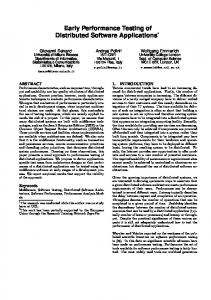
A NAND flash device consists of a set of pages, which are grouped into blocks. A unit can be equal to a block or multiple blocks. Each page contains a set of sectors. When new data is written to flash memory, rather than overwriting old data directly, the data is written on empty physical sectors and the physical sectors that contain the old data are marked as invalid. Since the empty physical sectors may reside in separate physical units, one logical unit (LU) containing data is mapped to a linked list of physical units (PU). STL manages this mapping from logical sectors (LS) to physical sectors (PS). This mapping information is stored in a sector allocation map (SAM), which returns the corresponding PS offset from a given LS offset. Each PU has its own SAM. Logical unit 7 SAM of physical unit 1 Logical offset Physical offset
0 1 2 3
3 2
Physical unit 1 LS0 LS1 LS1 LS0
SAM of physical unit 4 Logical offset Physical offset
0 1 2 3
Physical unit 4 LS2
0
Fig. 1. Mapping from logical sectors to physical sectors
Figure 1 illustrates a mapping from logical sectors to physical sectors where 1 unit consists of 1 block and 1 block contains 4 pages, each of which consists of 1 sector. Suppose that a user writes LS0 of LU7. An empty physical unit PU1 is then assigned to LU7, and LS0 is written into PS0 of PU1 (SAM1[0]=0). The user continues to write LS1 of LU7, and LS1 is subsequently stored into PS1 of PU1 (SAM1[1]=1). The user then updates LS1 and LS0 in order, which results in SAM1[1]=2 and SAM1[0]=3. Finally, the user adds LS2 of LU7, which adds a new physical unit PU4 to LU7 and yields SAM4[2]=0. 4.2 Multi-sector Read Operation USP provides a mechanism to simultaneously read as many multiple sectors as possible in order to improve the reading speed. The core logic of this mechanism is implemented 2
This section is taken from [13].
in a single function in STL. Due to the non-trivial traversal of data structures for logicalto-physical sector mapping (see Section 4.1), the function for MSR is 157 lines long and highly complex, having 4-level nested loops. Figure 2 describes simplified pseudo code of these 4-level nested loops. The outermost loop iterates over LUs of data (line 218) until the numScts amount of the logical sectors are read completely. The second outermost loop iterates until the LSes of the current LU are completely read (line 5-16). The third loop iterates over PUs mapped to the current LU (line 7-15). The innermost loop identifies consecutive PSes that contain consecutive LSes in the current PU (line 8-11). This loop calculates conScts and offset, which indicate the number of such consecutive PSes and the starting offset of these PSes, respectively. Once conScts and offset are obtained, BML READ rapidly reads these consecutive PSes as a whole (line 12).
01:curLU = LU0; 02:while(numScts > 0) { 03: readScts = # of sectors to read in the current LU 04: numScts -= readScts; 05: while(readScts > 0 ) { 06: curPU = LU->firstPU; 07: while(curPU != NULL ) { 08: while(...) { 09: conScts = # of consecutive PSes to read in curPU 10: offset = the starting offset of these consecutive PSes 11: } 12: BML_READ(curPU, offset, conScts); 13: readScts = readScts - conScts; 14: curPU = curPU->next; 15: } 16: } 17: curLU = curLU->next; 18:}
Fig. 2. Loop structures of MSR
For example, suppose that the data is “ABCDEF” and each unit consists of four sectors and PU0, PU1, and PU2 are mapped to LU0 (“ABCD”) in order and PU3 and PU4 are mapped to LU1 (“EF”) in order, as depicted in Figure 3(a). Initially, MSR accesses SAM0 to find which PS of PU0 contains LS0(‘A’). It then finds SAM0[0]=1 and reads PS1 of PU0. Since SAM0[1] is empty (i.e., PU0 does not have LS1(‘B’)), MSR moves to the next PU, which is PU1. For PU1, MSR accesses SAM1 and finds that LS1(‘B’) and LS2(‘C’) are stored in PS1 and PS2 of PU1 consecutively. Thus, MSR reads PS1 and PS2 of PU1 altogether through BML READ and continues its reading operation.
The requirement property for MSR is that the content of the read buffer should be equal to the original data in the flash memory when MSR finishes reading, as given by assert( ∀i.LS[ i]==buf[i]) inserted at the end of MSR. 3
SAM0~SAM4 Sector 0
1
0 1 2
Sector 1 Sector 2
SAM0~SAM4
E 1 AB C
3
Sector 3
PU0~PU4
3 F
0
2
(a) A distribution of “ABCDEF”
1
SAM0~SAM4
1
3 B 3
D
PU0~PU4
D F AC E
(b) Another distribution of “ABCDEF”
PU0~PU4
0 1 2
B 1 FE D
3
A C
(c) A distribution of “FEDCBA”
Fig. 3. Possible distributions of data “ABCDEF” and “FEDCBA” to physical sectors
In these analysis tasks, we assume that each sector is 1 byte long and each unit has four sectors. Also, we assume that data is a fixed string of distinct characters (e.g., “ABCDE” if we assume that data is 5 sectors long, and “ABCDEF” if we assume that data is 6 sectors long). We apply this data abstraction, since the values of logical sectors should not affect the reading operations of MSR, but the distribution of logical sectors into physical sectors does. For example, for the same data “ABCDEF”, the reading operations of MSR are different for Figure 3(a) and Figure 3(b), since they have different SAM configurations (i.e., different distributions of “ABCDEF”). However, for “FEDCBA” in Figure 3(c), which has the same SAM configuration as the data shown in Figure 3(a), MSR operates in exactly same manner as for Figure 3(a). Thus, if MSR reads “ABCDEF” in Figure 3(a) correctly, MSR reads “FEDCBA” in Figure 3(c) correctly too. In addition, we assume that data occupies 2 logical units. The number of possible distribution cases for l LSes and n physical units, where 5 ≤ l ≤ 8 and n ≥ 2, increases exponentially in terms of both n and l, and can be obtained by n−1 ∑
((4×i) C4 × 4!) × ((4×(n−i)) C(l−4) × (l − 4)!)
i=1
For example, if a flash has 1000 physical units with data occupying 6 LSes, there exist a total of 3.9 × 10²² different distributions of the data. Table 1 shows the total number of possible cases for 5 to 8 logical sectors and various numbers of physical units, respectively, according to the above formula. MSR has the characteristics of a control-oriented program (4-level nested loops) and a data-oriented program (large data structure consisting of SAMs and PUs) at the same time, although the values of PSes are not explicitly manipulated. As seen from Figure 3, 3
[15] describes a systematic method to identify this test oracle for MSR.
Table 1. Total number of the distribution cases PUs 4 l = 5 61248 l = 6 239808 l = 7 8.8 × 10⁵ l = 8 3.4 × 10⁶
5 290304 1416960 7.3 × 10⁶ 4.2 × 10⁷
6 9.8 × 10⁵ 5.8 × 10⁶ 3.9 × 10⁷ 2.9 × 10⁸
7 2.7 × 10⁶ 1.9 × 10⁷ 1.5 × 10⁸ 1.4 × 10⁹
8 6.4 × 10⁶ 5.1 × 10⁷ 5.0 × 10⁸ 5.6 × 10⁹
the execution paths of MSR depend on the values of SAMs and the order of PUs linked to LU. In other words, MSR operates deterministically, once the configuration of the SAMs and PUs is fixed.
5
Case Study on Paralleized Concolic Testing of the Flash Storage Platform
In this section, we describe a series of experiments for testing the multisector read (MSR) operation of the unified storage platform (USP) for a Samsung OneNAND flash memory [3]. Also, we compare the empirical results of applying distributed concolic testing with the results of the original concolic testing [14]. Our goal is to investigate the distributed concolic algorithm, focusing on its performance improvement and scalability when applied to MSR. We thus pose the following research questions. – RQ1: How does the distributed concolic algorithm improve the speed of concolic testing the MSR code? – RQ2: How does the distributed concolic algorithm achieve scalability when applied to the MSR code? 5.1
Environment Model
MSR assumes that logical data are randomly written on PUs and the corresponding SAMs record the actual location of each LS. The writing is, however, subject to several constraint rules; the following are some of the representative rules. The last two rules can be enforced by the constraints in Figure 4. 1. One PU is mapped to at most one LU. 2. If the ith LS is written in the kth sector of the jth PU, then the (i mod m)th offset of the jth SAM is valid and indicates the PS number k, where m is the number of sectors per unit (4 in our experiments). 3. The PS number of the ith LS must be written in only one of the (i mod m)th offsets of the SAM tables for the PUs mapped to the ⌊ mi ⌋th LU. To enforce such constraints on test cases, a test driver/environment model generates valid (i.e., satisfying the environment constraints) test cases explicitly by selecting a PU
∀i, j, k (LS[i] = P U [j].sect[k] → (SAM [j].valid[i mod m] = true & SAM [j].of f set[i mod m] = k & ∀p.(SAM [p].valid[i mod m] = f alse) i where p ̸= j and P U [p] is mapped to⌊ ⌋th LU )) m Fig. 4. Environment constraints for MSR
and its sector to contain the l th logical sector (PU[i].sect[j]=LS[l]) and setting the corresponding SAM accordingly (SAM[i].offset[l]=j). For example, Figure 3(a) represents the following distribution case: – LS[0]=‘A’, LS[1]=‘B’, LS[2]=‘C’, LS[3]=‘D’, LS[4]=‘E’, and LS[5]=‘F’ – PU[0].sect[1]=‘A’, PU[1].sect[1]=‘B’, PU[1].sect[2]=‘C’, PU[2].sect[3]=‘D’, PU[3].sect[0]=‘E’, and PU[4].sect[1]=‘F’. – SAM[0].valid[0]=true,SAM[1].valid[1]=true,SAM[1].valid[2] =true, SAM[2].valid[3]=true, SAM[3].valid[0]=true, and SAM[4].valid[1]=true (all other validity flags of the SAMs are false). – SAM[0].offset[0]=1,SAM[1].offset[1]=1,SAM[1].offset[2]=2, SAM[2].offset[3]=3,SAM[3].offset[0]=0, and SAM[4].offset[1]=1. Thus, the environment contraints for i = 2, j = 1, and k = 2 are satisfied as follows: LS[2] = P U [1].sect[2] → (SAM [1].valid[2 mod 4] = true & SAM [1].of f set[2 mod 4] = 2 & SAM [0].valid[2 mod 4] = f alse & SAM [2].valid[2 mod 4] = f alse & SAM [3].valid[2 mod 4] = f alse)
5.2
Test Setup for the Experiment
All experiments were performed on 64 bit Fedora Linux 9 equipped with a 3.6 GHz Intel Core2Duo processor and 16 gigabytes of memory. We utilized 16 computing nodes connected with a gigabit ethernet switch. We implemented Algorithm 2 in the open source concolic testing tool CREST [2]. However, since the CREST project is in its early stage, CREST has several limitations such as lack of support for dereferencing of pointers and array index variables in the symbolic analysis. Consequently, the target MSR code was modified to use an array representation of the SAMs and PUs. We used CREST 0.1.1 (with DFS search option), gcc 4.3.0, Yices 1.0.24 [8], which is an SMT solver used as an internal constraint solver by CREST for solving symbolic path formulas. Although CREST does not correctly test programs with non-linear arithmetic,
we could apply CREST to MSR successfully, because MSR contains only linear integer arithmetic. To evaluate the effectiveness of parallelized concolic testing (i.e., bug detecting capability), we applied mutation analysis [5] by injecting the following three types of frequently occuring bugs (i.e. mutation operators), as we did in our previous study [14]. The injected bugs are as follows: 1. Off-by-1 bugs – b11 : while(numScts>0) of the outermost loop (line 2 of Figure 2) to while(numScts>1) – b12 : while(readScts>0) of the second outermost loop (line 5 of Figure 2) to while(readScts>1) – b13 : for(i=0;i