This is a preprint of the article accepted for publication in Proc. SPIE, v. 9286, 92860D, 22-Aug-2014, DOI:10.1117/12.2060254 The off-print version is available at http://proceedings.spiedigitallibrary.org/proceeding.aspx?articleid=1900340
Scalable lidar technique for fire detection Andrei B. Utkin*a,b, Fernando Piedadea, Vasco Beixigaa, Pedro Motaa and Pedro Lousãa a INOV - INESC Inovação, Rua Alves Redol 9, Lisboa, Portugal 1000-029; b ICEMS, IST, Universidade Técnica de Lisboa, Av. Rovisco Pais 1, Lisboa, Portugal 1049-001 ABSTRACT Lidar (light detection and ranging) presents better sensitivity than fire surveillance based on imaging. However, the price of conventional lidar equipment is often too high as compared to passive fire detection instruments. We describe possibilities to downscale the technology. First, a conventional lidar, capable of smoke-plume detection up to ~10 km, may be replaced by an industrially manufactured solid-state laser rangefinder. This reduces the detection range to about 5 km, but decreases the purchase price by one order of magnitude. Further downscaling is possible by constructing the lidar smoke sensor on the basis of a low-cost laser diode. Keywords: lidar, fire surveillance, smoke sensor, remote sensing, optoelectronics, laser diode, artificial intelligence, signal processing
1. INTRODUCTION Lidar (LIght Detection And Ranging) is an active remote detection technique that uses an optical-range electromagnetic radiation. The principle of lidar operation is similar to that of radar; both technologies can be used in monitoring applications, their efficiency depends on the targets to be detected and recognized. For the specific application of fire surveillance, the lidar provides far better efficiency than radar, as the scale of the lidar operation wavelengths, 100-1000 nm, corresponds to the characteristic dimension of soot and water particles composing smoke. Thus these particles interact with the lidar probing beam much stronger than with the radio-frequency pulses emitted by radar1,2. Additional advantage of lidar is the possibility of emitting low-divergence beams using compact transmitters. This offers very long detection ranges, limited only by available laser pulse energy and beam jitter resulting from the turbulence along lengthy and nearly horizontal atmospheric paths3 — an important advantage of the technique with respect to conventional fire surveillance via visible or infrared imaging. Detecting smoke plumes of any temperature in any daylight conditions, lidar sensors does not require line-of-sight observation of flames or hot gases and can be operated round-the-clock. High sensitivity and spatial resolution of the lidar data enables a fire to be precisely detected at the early phase of its development, when the fire is still easy to extinguish. The lidar signal can be subjected to an inversion procedure, which yields the distribution of the extinction and backscattering coefficients along the laser pulse trajectory and, eventually, the estimation of smoke particle concentration. This makes the lidar an invaluable instrument for investigation of fire and smoke behavior in natural conditions as well as for the experimental verification of gasdynamic models for fire behavior. The first lidar assisted analysis of emissions produced by power plants, factories, and forest fires was carried out in late 1960s4,5. Since that time, the interest in lidar has been steadily increasing, and lidar methods 6-9, along with the algorithms for system optimization10 and lidar signal processing11-16, are now widely used for atmosphere research and monitoring. The paper is organized as follows: In section 2 we present the basic principles of smoke detection by lidar in terms of both equipment and methodology. Section 3 overviews the approaches to automated fire detection and the artificial intelligence algorithms developed by the authors, while section 4 discusses concrete implementations of the lidar sensors, the problem of technology scalability, and the main results in its development in Portugal since 2000. The accomplishment of this work is summarized and directions of future research are indicated in the conclusion section 5.
*
[email protected]; phone 351 213100426; fax 351 213100445; www.inov.pt
92860D-1
2. BASIC PRINCIPLES OF FIRE DETECTION BY LIDAR 2.1 Equipment Schematics of automated lidar detection of fires are given in Fig. 1. A laser generated short, nanosecond-range light pulses, which propagate through the atmosphere in the form of beam, whose lower divergence is achieved, if necessary, by introduction of the beam-forming optics. When the beam hits some target (dust/smoke particles, trees, ground, etc.), a part of the probing light is scattered backward to the lidar sensor, eventually entering the light gathering optical system of the receiver. This system focuses radiation on the photodetector, where the light power Prec is converted into an electric signal, which is amplified, digitized by a data acquisition plate and directed to the lidar control software. Here the digital signal S is stamped with the detection time tm , reckoned from the moment of laser pulse emission, and the azumuth/elevation angles , reported for t tm by the laser beam control unit
Prec S , tm , , Sm , , : Sm S tm .
Transmitter
Laser
(1)
Beam forming optics
Start Synch t = 0
R
Analog signal S(t) Preamplifier
Data acquisition
Light gathering optics Photodetector
Receiver
Alarm signal and target coordinates
Hillside signature Smoke plume signature Rsp
Digitized signal {Si}
Signal recognition
Peaks due to atmospheric and electronic noise
R, m
Figure 1. Schematics of a lidar sensor for automatic fire surveillance.
The coordinates of the target detected at t tm are initially characterized by the spherical-coordinate triad Rm , , , where the lidar-to-target distance Rm is defined from the time-of-flight as Rm ctm / 2 , c being the speed of light. In view of this dependency, the lidar signal is conventionally expressed as a function of R rather than t rec Sm S Rm , Rm m R, m 0,1,..., M , M Rmax /R .
(2)
Here R c / (2 F ) is the sampling distance, which depends on the operating frequency of the data acquisition plate F , rec and Rmax represents the maximum distance to be recorded for given signal S m m 1 .
M
2.2 Theoretical background For the majority of photodetectors the lidar signal can be linked with the collected light power Prec through the equation17,18
92860D-2
S m G * ph Prec Rm S m S0 , G * GRL ,
(3)
where G* is the total gain, G the (dimensionless) electronic gain, RL the load resistance, and Sm and S0 the noise and
constant background component respectively. The product ph Prec Rm represents the unbiased current, ph being the photodetector responsivity. Expressing the power Prec via the lidar equation19,20 one can get from Eq. (3) an expression connecting the discrete-time lidar signal with the probing medium properties
Sm S Rm C0
Rm 2 m
R
exp 2 R dR Sm S0 , m 0,1,..., M , Rm
0
(4)
where C0
c * G ph El Arec rec tr 2
(5)
is the lidar constant (here El is the energy of the probing pulse at the moment of its emission to the atmosphere, tr and
rec the transmitter and receiver efficiencies, and Arec the area of the entrance pupil of the light gathering optics) while ( R ) and ( R) are the extinction and backscattering coefficients of the medium (atmosphere or target) at the distance R along the probing beam. For the smoke-free areas, the last two parameters can be estimated on the basis of several light absorption and scattering models. The most straightforward way is to estimate through the local visibility21,22 and then to assess using some sufficiently general interrelation between the atmospheric extinction and scattering. E.g., for the Klett’s method13-15 one assumes an extinction-to-backscatter correlation power law13 and the requirement of the backscatter calibration at the farrange from the lidar site23. The extinction and backscatter at fire location is estimated on the basis of Mie theory24 and different gas-dynamics models of the smoke plume, based on conservation laws1,2, "top hat" Morton's approximation3,7,25, 3D RANS (Reynolds-averaged Navier-Stokes equations)26-28, or more complicated numerical algorithms included in dedicated commercial software packages29,30. While the above algorithms provide an assessment of the smoke-related component of the lidar signal, the second term of relation (4), Sm , can be estimated using specific models. Usually, the following noise components are taken into account: thermal and amplification noise, depending on the detector temperature, electronic bandwidth, and the noise figure of concrete amplifier31-33; shot noise, originating from the discrete nature of electric charge and depending from the excess-noise factor, gain and responsivity32,33; background-radiation noise, resulting from detection, apart from the emitted laser light, the scattered (or, sometimes, even direct) sunlight form the sky within receiver's field of view 32,33; and the noise due to photodetector dark current, as well depending on the electronic bandwidth, excess-noise factor, and gain31,34. The (constant) background component is conventionally estimated by averaging the signal recorded beyond the det instrument detection range Rmax ,
S0
m2 1 det rec , Rm1 Rm 2 Rmax Sm , m1 , m2 : Rmax m2 m1 1 m m1
(6)
where no target signature (retroreflection peak) is expected35. To improve the signal-to-noise ratio, N (partial) signals S {{S m( n ) }mM1}nN1 ,
(7)
from several laser pulses are usually accumulated in a mean signal S m( N )
1 N
N
S n 1
(n) m
, m 0,1,..., M .
92860D-3
(8)
A rough estimation of this noise reduction based on the normal-distribution (Poisson-Gauss) model leads to a dependence of the signal-to-noise ratio SNR with the square root of the number of lidar returns accumulated
SNR( N ) N SNR(1) .
(9)
In practice, however, the noise distribution does not follow the Gaussian pattern, and significant reduction of noise is observed for N not exceeding some critical value, about 100 to 1000, depending on the detector type. Concretization of general relations (3)-(9) for three practically important cases of receivers based on a photomultiplier (PMT), photodiode (PD) and avalanche photodiode (APD) is discussed in Refs. 1-3,6-8,36 Corresponding models are primary used for estimation of the smoke-plume detection range for different lidar configurations operating at different wavelengths7. However, they are also employed for optimization of lidar sensors10 and their location for fire surveillance in hilly terrain37,38. Cornerstone relation (3), also called the lidar equation19, serves as a basis for several inversion procedures restoring the backscatter, extinction and, finally, the particle concentration profiles along the laser beam direction13-15. Performing variation of the laser beam azimuth and elevation , one can combine the resulting data cloud into a 3D image of the plume. Several examples of such data treatment are given in Ref. 9 and illustrated in Figs. 6 and 7 therein. More elementary expressions describing propagation and attenuation of laser radiation in the atmosphere are used for assessment of the eye-hazard range of the laser transmitter8,9.
3. AUTOMATED RECOGNITION OF SMOKE-PLUME SIGNATURES The only effective way to minimize damage caused by forest fires is to detect them at the initial, less advances stage, and to extinguish them promptly. Today's systems of early fire detection are mainly based on human surveillance, traditionally implemented as 24-hour monitoring by human observers located on specially chosen spots or watchtowers. Technically and functionally better wildfire monitoring system could be implemented using network imaging. In this case remotely controlled video cameras are installed on various monitoring spots, and the human observers are located in the observation center39. The next more advanced step in forest fire monitoring is automatic surveillance and automatic early forest fire detection system. In this scenario, the operator is not responsible for routine image analysis anymore: the system do this job, but his/her decision is final when the suspicious behavior is detected and the alarm is issued 40. The lidar-assisted automatic forest fire surveillance has significant advantages over the infrared and video imaging methods not only due to its potentially higher sensitivity, but also because of less complicated alarm recognition task: The smoke signatures must be promptly recognized and false alarms rejected in the one-dimensional lidar signals (8) rather than in 2D data provided by the imaging systems39,40. During the lidar monitoring, the false alarms frequently result from objects causing intense backscattering, such as fog, trees, birds, hills, high-tension cables, etc. However, inhomogeneities of the refraction index caused by atmospheric phenomena may also lead to spurious peaks in the lidar signal. In general, lack of knowledge of the aerosol distribution in the atmosphere and random changes in atmospheric refraction index and their dependence on weather conditions, make it difficult to use parametric relations described in the previous subsection. That is why the contemporary methods of fire detection by various techniques, including lidar, rely upon the artificial intelligence (AI) algorithms, in particular, on the specially trained artificial neural networks. As discussed in Ref.22, an early stage of a fire, the characteristic spread of the smoke plume in the laser-beam propagation direction Rsp is about 8–11 m. To reveal the specific structures that make the smoke-plume signatures different from other signal peaks, the data acquisition plate must digitize the photodetector output with a sampling interval R ~ 0.75 m or less, providing at least 10–15 signal points within the retroreflection peak. For the instrument det 5 km, the length of the discrete-time sequence to be processed detection range Rmax det M max
det Rmax 5000 6.7 103 R 0.75
(10)
is much larger than in other lidar applications11,41, as fire may occur anywhere within the surveillance range, so no narrower region of interest can be selected a priori (the only data that can be discarded immediately are signal points for
92860D-4
rec
det rec R Rmax the distances Rm : Rmax , that is, the segment {S m( N ) }mMmaxM det ). The distance to the smoke plume Rsp (see Fig. 1) max
must be determined simultaneously, resulting in an additional output, codifying Rsp in the case of positive detection. As other AI methods, the algorithms for automatic smoke detection require incorporating all a priori information about the targets in order to simplify the overall structure and facilitate the recognition42-44. The analysis of the lidar signal provides the following a priori information43: (a) The smoke-plume signatures manifest themselves in the raw lidar signal as peaks whose characteristic width (several meters) is much less than the typical distance to the smoke plume (from hundred meters to several kilometers). (b) The position of the smoke-signature maximum corresponds to the desired distance to the smoke plume. (c) The local noise level may be estimated as the root-mean-square of the signal just before and after the peak and a segment of lidar signal of length ~ 3 Rsp containing the smoke-signature maximum in its center, is supposed to provide information on both the smoke-plume signature shape and local noise. (d) The ratio of the peak amplitude to the mean local noise, called peak-to-noise ratio (PNR), represents an important scaleindependent characteristic of the peak magnitude, closely linked with the probability of the peak to be a target signature rather than a clutter signal. For this reason, it is worthwhile to treat PNR as an invariant characteristic feature to be extracted and independently presented for recognition. The knowledge and invariances are incorporated into the AI algorithms via a preprocessing procedure36,43,45: The raw lidar signal, consisting of several thousand points, is viewed by the preprocessing software through a window of several tens of points (~ 3Rsp / R ) that moves along the signal curve in order to define a region of interest. The window motion stops whenever a local maximum coincides with the window center Rw and the corresponding peak-to-noise ratio PNR( Rw ) is calculated. If this peak-to-noise ratio is lower than some chosen constant threshold value (typically, from 3 to 5), the peak is considered to be too small to correspond to a smoke plume and the observation window continues its motion along the curve. Otherwise the pattern within the region of interest is sent to the recognition procedure. The corresponding peak-to-noise ratio is also introduced to the recognition procedure. When the procedure identifies the signal peak as a target signature, current window position provides the desired distance to the target Rsp Rw along the beam direction (defined by current values of and ). Particular recognition procedures are being developed by the INOV team since 2000, along with construction and scaling of the lidar sensors (to be discussed in the next section). The initially proposed neural-network algorithm based on a simple perceptron12 was soon upgraded to a multi-perceptron structure composing a committee machine16. A new procedure based on ROC curves and the Neyman-Pearson criterion was used for choosing the optimal number of training epochs for neural networks, consequently avoiding over-fitting. The generalization properties of the committee machines were tested using patterns created by adding random noise to patterns obtained experimentally. A committee machine composed of two single-layer perceptrons led to a true detection efficiency of 95%. Further improvement, 97% and 0.9% for the true detection and false alarm rate, was achieved by introduction of the specially developed algorithm with learning rate adaptation46. Simultaneously, a more profound development of the algorithms of Ref. 16 enabled the team to implement a recognition procedure47 with even less percentage of the false alarms (0.55%), achieved at the expense of slightly worse performance in true detection (94.4%). Finally, a drastic diminishing of the false alarm rate down to 0.041% was achieved using committee machines and more advanced preprocessing that included extraction, along with PNR, additional features, such as average-amplitude and maximum-amplitude ratios (see Ref.48 for details). An alternative family of developed recognition procedures borrowed the approach from the radial-basis function network theory18,43,45,49. Classification is carried out by a single perceptron whose efficiency is enhanced by nonlinear threshold binarization transformation to higher dimensional space, similar to Bhattacharya's processing of lidar signal for the detection of fish in near-shore waters11. Presently this algorithm is used for recognition of signals from laser-diode lidar sensors, demonstrating 8.5% misdetection rate and 0.056% false alarm rate. This efficiency is similar to that of a far more complicated committee machine composed of four single-layer perceptrons (7.4% misdetection rate and 0.041% false alarm rate). At the same time, the signal binarization algorithm allows nearly one order of magnitude faster training. Moreover, since the learning procedure does not depend on the choice of the best classifier, it can be strictly formalized and performed by users without special training. The algorithm does not contain repetitive iteration routines like training epochs in the case of gradient-descent methods and the global minimum of the classification error for given training set is readily achieved by a sequence of matrix operations of guaranteed stability.
92860D-5
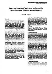
4. IMPLEMENTATION OF THE LIDAR SURVEILLANCE: SCALABILITY PROBLEM AND MAJOR ACHIEVEMENTS In Portugal, the lidar fire surveillance systems were first developed on the basis of high-power Q-switched solid-state lasers, aiming to cover large forest areas with a single lidar sensor. The most successful configuration6 provided experimental proof of detecting small-scale experimental fires (burning rate of ~26 g/s) up to the distance of about 6.5 km with SNR ~50-100. Corresponding theoretical models of subsection 2.2 predict the range of reliable ( SNR 5 ) detection of such fires being as long as 10-20 km, depending on the atmospheric and daylight conditions. The sensor sensitivity was sufficient for inversion of the lidar returns from smoke plumes produced by controlled middle-scale wildland fires (burning rate of ~20 kg/s, organized in Portugal within the scope of Gestosa project50), located at the distances of about 1 km from the instrument. Moreover, using the lidar technique at the high laser pulse energy mode enabled the team to assess the dynamics of low-concentration traffic aerosol in Lisbon during the European Carfree Day campaign51 (Fig. 2 illustrates the lidar sensor installed in September 2000 at the Restauradores Square).
Figure 2. A long-range lidar sensor developed on the basis of the Q-switched Nd:YAG ILTI laser (producing 30/90 mJ pulses at the wavelengths 532/1064 nm) and photodetector FEU-83 with Peltier cooling (having the dark current of about 400 nA and gain of ~105). Detailed technical characteristics of this sensor are listed in Tab. 1 of Ref. 6
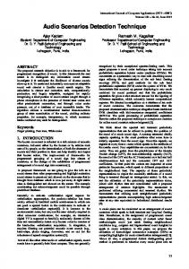
Difficulty in introducing such instruments to the market is connected with their high production and maintenance costs, high energy consumption, low reliability, need of frequent and complicated servicing and bulkiness. In addition, highpower laser pulses present a serious hazard to the eye, which involves obligatory and costly protective measures 9. Thus since 2003 the subsequent successful development of the lidar fire surveillance was always carried out aiming to downscale the technology in order to create more compact, robust, and cheaper sensors. Along this direction, the obvious and very promising step is to take an advantage of cost-effective and highly optimized optoelectronic schemes already developed for industrial laser rangefinders. Basically, the only modification required is to substitute the range-definition electronics, which only extracts position of the most pronounced retroreflection peak(s), by a far more complicated data processing system that deals with the entire (raw) signal, (2) or (8). In this way, the best results were obtained with the architecture build around an Er:glass laser generating 8 mJ pulses of eye-safe 1540 nm radiation. Due to the light-gathering optics with the diameter as small as 38 mm, the instrument has weight of only about 3 kg. Application of the InGaAs avalanche photodiode, possessing significant internal gain, enabled the detection range det Rmax to be extended nearly three times with respect to the similar sensor with pin photodiode. For a typical initial-stage fire consuming 0.05 kg of wood per second, the range of reliable detection (SNR~5) is about 1.5 km, see the plot of Fig. 3.
92860D-6
SNR
InGaAs avalanche photodiode
Pin photodiode
R, m Figure 3. Comparison of two smoke sensors based on the mass-production laser-rangefinder optical scheme with an 8 mJ Er:glass laser and Ø38 mm light gathering optics made on the basis of the theoretical model described in subsection 2.2: one with pin photodiode and the other with avalanche photodiode. SNR is calculated with respect to detection of a smoke plume produced by campfire of burning rate of 0.05 kg/s and fire diameter of 0.5 m, no signal accumulation is implied. The laser beam divergence is 0.9 mrad, and the height of intersection of the plume with the laser beam is 10 m.
The instrument possesses relatively low probing beam divergence of 0.9 mrad, and low power consumption, ~5 W at 12 V (DC). Specificity of the lasing material and the absence cooling system do not permit to maintain the laser-pulse repetition rate above 0.2 Hz. While the characteristic price scale for the (as a rule, custom-developed) long-range lidar is $100000, the instruments built on the basis of (mass-production) laser rangefinder schemes are one order of magnitude cheaper and thus can be successfully introduced as components of the commercial fire surveillance systems 52. Usually such systems comprise a lidar sensor and a video/IR camera with zoomed, high-quality imaging for independent confirmation of fire alarm (Fig. 4).
Figure 4. The developed Er:glass smoke sensor sharing the same pan-tilt with the Ciclope video camera. Watchtower at Proença-a-Nova Municipality, Central Portugal, installed within the framework of the Project AGRO (Integrated telesurveillance and automatic forest fire detection system) funded by Portugese Ministry of Agriculture53.
92860D-7
Other extremely important and steadily growing market comprises systems for fire surveillance in industrial environments. As the market is characterized by a large number of relatively small enterprises, further scaling of the technology in order to lower the price down to ~$1000 was necessary for successful promotion of the lidar-assisted fire detection systems. These systems can be competitive in open-space industrial installations — such as warehouses, tunnels, parkings, etc., which may contain large combustible loads and present high fire risk — where the simpler and cheaper thermal sensors and photoelectric/ionization smoke detectors are not effective. For the case in question, the key factor of sensor development is the fact that a typical area to be monitored is of tens of hectares in size. Thus the det ~ 200 m can be regarded sufficient for most requirement for smoke-plume detection range is rather loose, and Rmax practical needs. In these circumstances the lidar sensor may be based on transmitters built around an extremely cheap laser-diode array. One among laser-diode lidar sensors for fire surveillance developed by INOV in 2005-2009 within the framework of the project SIDAI (Integrated system for automatic detection of fires in industrial installation)54 is shown in Fig. 5.
Figure 5. Lidar smoke sensor developed on the basis of a laser diode array and an APD mounted in a standard protective case and installed on a standard pan-tilt for video camera. Both the transmitter (right) and receiver (left) optics are assembled within Ø1" Thorlabs lens mounting tubes.
Compactness of the optoelectronic system, mainly comprising cheap elements manufactured by Thorlabs, enabled the lidar to be assembled within a standard protective case for video cameras. A laser-diode array generates 1.1 μJ, 17 ns laser pulses with the repetition rate of about 100 Hz (effectively restricted by the velocity of data transmission from the sensor to the processing computer-controlled center) at the wavelength of 905 nm. The eye safety is guaranteed due to low radiation fluence of the laser beam, initially expanded by a beam-forming lens to the diameter of 20 mm and having the divergence of ~3 mrad. Estimation of the total transmitter efficiency is 0.85. The receiver of the total efficiency of 0.75 has the input pupil of 23 mm (restricted by rings retaining Ø1" light gathering lens, Arec 4 cm2) and is provided with the narrowband spectral filter ( 905 nm, 25 nm). With the APD gain of 100, the receiver possesses the total photoelectric sensitivity of ~100 kV/W and, for initial-stage fire of the burning rate of 0.15 kg/s, provides the det 2 ) 24.6 ha. reliable detection range (i.e., SNR 5 ) of about 280 m, potentially covering the area ( Rmax The discussed laser-diode lidar technology is being developed toward more efficient detection within the same manufacturing cost range. Till now, the following main improvements were implemented:
Introduction of laser diode array with integrated driver stage. The placement of the field-effect transistor (FET) and the energy storing capacitors within the array body, which significantly reduce the spreading and distortion of the driving electric pulse, permit emitting sharper and more efficient radiation pulses.
92860D-8
Implementation of the receiver optical train based on Ø2", rather than on Ø1", light gathering lens ( Arec 18.1 cm2). This increases the collected radiation power Prec more than four times.
Introduction of custom data acquisition electronics based on an interleaved architecture comprising four 10-bit ADC modules, operating at 100 MSPS (mega samples per second), thus achieving the total digitalization efficiency of 400 MSPS. With this digitalization rate we achieve the spatial resolution of 37.5 cm, enabling the lidar to record finer structures of distributed targets, thus increasing the efficiency of their recognition.
Development of new local data treatment electronics capable of in-place processing (averaging) up to 128 lidar returns, which (1) reduced the traffic between the instrument and the command server more than 2 orders of magnitude and (2) significantly alleviated the data congestion. This enables the sensor to generate probing pulses at frequencies up to 10 kHz, unleashing the full capacity of the transmitter.
Replacement of the Ethernet-type cable connection with the command center by wireless communication, which significantly reduces expenses associated with the system installation.
Assemblage of the optomechanical units within a specially designed light protective case.
The upgraded lidar sensor, depicted in Fig. 6, is now passing the test and benchmarking stage. The detection range of more than 1 km with respect to solid targets is confirmed, and at least two-fold extension of the detection range with respect to small-scale fires is expected. Remarkably, the improved sensitivity not only extends the range of fire detection, but permits, within the same range, to detect fires at each time earlier stages, when the fire is small and easy to extinguish.
Figure 6. Upgraded version of the laser-diode lidar sensor shown in Fig. 5 with integrated laser diode driver, Ø2" light gathering optics, faster data acquisition and communication systems, and wireless networking.
5. CONCLUSION AND FUTURE WORK The reported work provides strong conceptual, theoretical, and experimental proof of excellent scalability of the lidar fire detection technique, which can be implemented at adaptive cost in different segments of the fire surveillance market. Such flexibility of lidar technical solutions opens the prospects of improvement of the lidar systems developed so far along the following lines: Long-range sensors based on high power lasers: Reducing the size and weight characteristics by implementing transmitters on the basis of diode-pumped, rather than lamp-pumped, solid-state lasers. This increases the pumping efficiency and thus alleviates the requirements to the power supply and cooling systems, having very significant input to the total sensor dimension and mass. The same measure drastically augments the time of unattended operation and thus decrements the maintenance costs. Remarkably, recent advances in optoelectronics make the diode-pump laser architectures each time more affordable. As the detection is carried out with a single wavelength, the weight of largeaperture light gathering lenses can be drastically reduced by introducing thin Fresnel optics. Middle-range sensors based on modified laser rangefinders: Increasing of the transmitter efficiency by introduction of new lasing media for direct generation of radiation pulses of sufficient energy at an eye-safe wavelength. This measure can increase the pulse repetition range and therefore extend the detection range via more substantial signal accumulation during reasonable time.
92860D-9
Short-range sensors based on laser diodes: Further increase of the radiation-pulse energy invoking new, each time more powerful laser-diode arrays; increase of the lidar sensitivity using contemporary lightweight optics with larger aperture. Large number of accumulated returns N opens the prospect of extracting additional information from the set of detected signals S defined by expression (7): simultaneously with the mean signal {S m(N) }mM1 another, "statistical" image of the radiation-target interaction can be constructed without introduction of additional optoelectronic elements via M components of the standard signal deviation in each sampling point m
m( N )
1 N
S N
n 1
(n) m
S m( N ) , m 1, 2,..., M . 2
(11)
Bearing in mind that the standard deviations (11) can be expressed in the form
m( N ) S m2
(N )
S m( N ) , where 2
S m2
( N ) def
1 N
S N
n 1
(n) 2 m
,
(12)
the data acquisition system does not need to store all the partial signals: it is sufficient to accumulate signal amplitudes and their squares.
ACKNOWLEDGMENTS This research has been supported in part by: Ministry of Agriculture (Portugal), within the framework of project AGRO (Integrated telesurveillance and automatic forest fire detection system); AdI (Agência de Inovação, Portugal), within the framework of POCI 2010 program (FEDER funded), project SIDAI (Integrated system for automatic detection of fires in industrial installation); and Portuguese national program QREN—Sistema de Incentivos à Investigação, Desenvolvimento Tecnológico e Inovação da Região Autónoma da Madeira II within the framework of the project SDOAM (Development of a risk detection system based on active multi-functional optoelectronic sensors using LIDAR technology).
REFERENCES [1] Lavrov, A. and Vilar, R., "Application of lidar at 1.54 micron for forest fire detection," Proc. SPIE 3868, 473-477 (1999). [2] Lavrov, A. and Vilar, R., "Estimation of required parameters for detection of small smoke plumes by lidar at 1.54 μm," Applied Physics B 71(2), 225-229 (2000). [3] Vilar, R., Lavrov, A., Utkin, A. and Fernandes, A., "Comparison of eye-safe UV and IR lidar for small forest fire detection," Proc. SPIE 4542, 280-285 (2002). [4] Hamilton, P. M., "The Application of a Pulsed-Light Rangefinder (Lidar) to the Study of Chimney Plumes," Philos. Trans. R. Soc. Lond. A 265, 153-172 (1969). [5] Hinkley, E. D., [Laser monitoring of the atmosphere], Springer, Berlin, (1976). [6] Utkin, A. B., Lavrov, A. V., Costa, L., Simões, F. and Vilar, R., "Detection of small forest fires by lidar," Appl. Phys. B 74(1), 77-83 (2002). [7] Lavrov, A., Utkin, A. B., Vilar, R. and Fernandes, A., "Application of lidar in ultraviolet, visible and infrared ranges for early forest fire detection," Appl. Phys. B 76(1), 87-95 (2003). [8] Utkin, A. B., Fernandes, A., Simões, F., Lavrov, A. and Vilar, R., "Feasibility of forest-fire smoke detection using lidar," Int. J. Wildland Fire 12(2), 159-166 (2003). [9] Utkin, A. B., Fernandes, A. M., Lavrov, A. V. and Vilar, R. M., "Eye-safe lidar measurements for detection and investigation of forest-fire smoke," Int. J. Wildland Fire 13(4), 401-412 (2004). [10] Cordoba, A., Vilar, R., Lavrov, A., Utkin, A. B. and Fernandes, A., "Multi-objective optimisation of lidar parameters for forest fire detection on the basis of a genetic algorithm," Opt. Laser Technol. 36(5), 393-400 (2004). [11] Bhattacharya, D., Pillai, S. R. and Antoniou, A., "Waveform classification and information extraction from LIDAR data by neural networks," IEEE Trans. Geosci. Remote Sens. 35(7), 699-707 (1997).
92860D-10
[12] Fernandes, A., Utkin, A. B., Vilar, R. and Lavrov, A., "Recognition of smoke signatures in lidar signal with a perceptron," Proc. WMC Systemics Cybern. Informat. IX, 504-509 (2002). [13] Klett, J. D., "Stable analytical inversion solution for processing lidar returns," Appl. Opt. 20(2), 211-220 (1981). [14] Klett, J. D., "Lidar calibration and extinction coefficients," Appl. Opt. 22(4), 514-515 (1983). [15] Klett, J. D., "Lidar inversion with variable backscatter/extinction ratios," Appl. Opt. 24(11), 1638-1643 (1985). [16] Fernandes, A., Utkin, A., Lavrov, A. and Vilar, R., "Classification of lidar signals by committee machines applied to automatic forest fire detection;" Proc. JC Inf. Sci., 1585-1588 (2003). [17] Busch, K. W. and Busch, M. A., [Multielement Detection Systems for Spectrochemical Analysis], WileyInterscience, New York (1990). [18] Utkin, A. B., Lavrov, A. and Vilar, R., "A simple neural-network algorithm for classification of lidar signals applied to forest-fire detection," Proc. IJC on Comput. Intelligence, 569-574 (2009). [19] Measures, R. M.; [Laser Remote Sensing], John Wiley and Sons, New York (1984). [20] Lavrov, A., Utkin, A. B., Vilar, R., "Simple eye-safe lidar for cloud height measurement and small forest fire detection," Opt. Spectrosc. 109(1), 144-150 (2010). [21] Nilssson, B., "Meteorological influence on aerosol extinction in the 0.2–40-μm wavelength range," Appl. Opt. 18(20), 3457-3473 (1979). [22] Utkin, A. B., Lavrov, A., Vilar, R., "Laser rangefinder architecture as a cost-effective platform for lidar fire surveillance," Opt. Laser Technol. 41(7), 862-870 (2009). [23] Molina, C., López, M. A., Reba, M. N. M. and Rocadenbosch, F., [Elastic (lidar-data) inversion algorithms], Universitat Politecnica de Catalunya, Barcelona (2013). [24] Hulst, H. C. van de, [Light Scattering by small particles], John Wiley and Sons, N.Y., (1957). [25] Morton, B. R., "Modeling fire plumes," 10th Symp. on Combustion, The Combustion Institute, Pittsburg, 973-982 (1965). [26] Lavrov, A., Utkin, A. B., Vilar, R., "Experimental and theoretical investigation of forest fire detection by a portable eye-safe lidar operating at 1540 nm," Proc. SPIE 7131, 71312J (2009). [27] Novozhilov, V., "Computational fluid dynamics modelling of compartment fires," Progress Energy Combustion Sci. 27(6), 611-666 (2001). [28] Lavrov, A., Utkin, A. B., Vilar, R., Fernandes, A., "Evaluation of smoke dispersion from forest fire plumes using lidar experiments and modelling," Int. J. Therm. Sci. 45(9), 848-859 (2006). [29] CFD for design engineers, CHAM - UK Headquaters, London (2014), www.cham.co.uk [30] Utkin, A. B., Lavrov, A., Vilar, R., "Application of rangefinder for small forest fire detection," Proc. SPIE 6359, 635915 (2006). [31] Yariv, A., [Optical Electronics], Saunders College Publishing: Philadelphia (1991). [32] Youmans, D. G., Garner, R. and Peterson, K. R., "Dust cloud density estimations using a single wavelength lidar," Proc. SPIE 2271, 13-28 (1994). [33] Overbeck, J. A., Salisbury, M. S., Mark, M. B. and Watson, E. A., " Required energy for a laser radar system incorporating a fiber amplifier or an avalanche photodiode," Appl. Opt. 34, 7724-7730 (1995). [34] Saleh, B. E. A. and Teich, M. C., [Fundamentals of Photonics]; John Wiley & Sons, N.Y. (1991). [35] Durieux, E. and Fiorani, L., "Data processing." In: Bösenberg, J., Rrassington, D., Simon, P. C., [Instrument Development for Atmospheric research and Monitoring], Springer, Berlin, 87-94 (1997). [36] Utkin, A. B., Lavrov, A. and Vilar, R., "Active methods of early forest fire detection," Proc. SPIE 7994, 799414 (2011). [37] Fernandes, A. M., Utkin, A. B., Lavrov, A. V. and Vilar, R. M., "Calculation of the optimal location and minimum number of lidar apparatuses required for early forest fire detection in hilly terrain," Proc. SPIE 5575, 106-115, (2004). [38] Fernandes, A. M., Utkin, A. B., Lavrov, A. V. and Vilar, R. M., "Optimisation of location and number of lidar apparatuses for early forest fire detection in hilly terrain," Fire Safety J. 41(2), 144-154, (2006). [39] Stipanicev, D., Stula, M., Krstinic, D., Seric, L., Jakovcevic, T. and Marin Bugaric, M., "Advanced automatic wildfire surveillance and monitoring network," Proc. VI International Conference on Forest Fire Research (2010). [40] Alkhatib, A. A. A., "A review on forest fire detection techniques," Int. J. Distrib. Sens. Netw. 2014, 597368 (2014). [41] Mitra, V., Wang, C. J. and Banerjee, S., "Lidar detection of underwater objects using neural networks with linear prediction and Fourier transform for feature extraction," Proc. of Application of Neural Networks in Engineering 13, 695-700 (2003). [42] Anderson, J. A. and Rosenfeld, E., [Neurocomputing: Foundations of Research], MIT Press, Cambridge, (1988).
92860D-11
[43] Utkin, A. B., Lavrov, A. and Vilar, R., "Fire Surveillance and Evaluation by Means of Lidar Technique." In: Bennett, R. P., [Fire Detection], Nova Science Publishers, New York, 41-78 (2011). [44] Haykin, S., [Neural Networks], 2nd ed., Prentice Hall, London (1999). [45] Utkin, A. B., Lavrov, A. V. and Vilar, R. M., "Low-cost active optical system for fire surveillance," Opt. Spectrosc. 106(6), 926-936 (2009). [46] Fernandes, A. M., Utkin, A. B., Lavrov, A. V. and Vilar, R. M., "Neural network based recognition of smoke signatures from lidar signals," Neural Process. Lett. 19(3), 175-189 (2004). [47] Fernandes, A. M., Utkin, A. B., Lavrov, A. V. and Vilar, R. M., "Development of neural network committee machines for automatic forest fire detection using lidar," Pattern Recogn. 37(10), 2039-2047 (2004). [48] Fernandes, A. M., Utkin, A. B., Lavrov, A. V. and Vilar, R. M., "Design of committee machines for classification of single-wavelength lidar signals applied to early forest fire detection," Pattern Recogn. Lett. 26(5), 625-632, (2005). [49] Utkin, A. B., Lavrov A. and Vilar R., "Automatic recognition of smoke-plume signatures in lidar signal," Proc. SPIE 7131, 71312K (2009). [50] Viegas, D. X., Cruz, M. G., Ribeiro, L. M., Silva A. J., Ollero, A., Arrue, B., Dios, R., Gomez-Rodriguez, F., Merino, L., Miranda, A. I. and Santos, P., "Gestosa fire spread experiments," Forest fire research and wildland fire safety: Proc. IV Int. Conf. on Forest Fire Research, Milpress, Rotterdam, 121 (2002). [51] Rego, S., "Metade ficou em casa," Correio da Manhã, 23 September, 12 (2000). [52] www.inov.pt/pages_e/monitoring/tele_florestal_e.php [53] www.inov.pt/pages_e/electronics/agro_e.php [54] www.inov.pt/pages_e/electronics/sidai_e.php
92860D-12