Dec 18, 2014 - Quantum logic gates are the key elements in quantum computing. ... gates. CNOT gates supplemented with single-qubit rotations are widely ...
OPEN SUBJECT AREAS: QUANTUM OPTICS QUBITS QUANTUM INFORMATION
Received 23 July 2014 Accepted 1 December 2014 Published 18 December 2014
Correspondence and requests for materials should be addressed to F.-G.D. (fgdeng@bnu. edu.cn)
Scalable quantum computing based on stationary spin qubits in coupled quantum dots inside double-sided optical microcavities Hai-Rui Wei & Fu-Guo Deng Department of Physics, Applied Optics Beijing Area Major Laboratory, Beijing Normal University, Beijing 100875, China.
Quantum logic gates are the key elements in quantum computing. Here we investigate the possibility of achieving a scalable and compact quantum computing based on stationary electron-spin qubits, by using the giant optical circular birefringence induced by quantum-dot spins in double-sided optical microcavities as a result of cavity quantum electrodynamics. We design the compact quantum circuits for implementing universal and deterministic quantum gates for electron-spin systems, including the two-qubit CNOT gate and the three-qubit Toffoli gate. They are compact and economic, and they do not require additional electron-spin qubits. Moreover, our devices have good scalability and are attractive as they both are based on solid-state quantum systems and the qubits are stationary. They are feasible with the current experimental technology, and both high fidelity and high efficiency can be achieved when the ratio of the side leakage to the cavity decay is low.
Q
uantum logic gates are the basic elements to realize quantum computation and quantum information processing. It is well known that the controlled-not (CNOT) gate is one of the most efficient quantum gates. CNOT gates supplemented with single-qubit rotations are widely adopted as the standard model of universal quantum computation1–5. It has been shown that the synthesis of a general two-qubit gate requires 3 CNOT gates and 15 elementary one-qubit rotations in the worst case6–8. The ‘‘small-circuit’’ structure for twoqubit gates in terms of CNOT gates has been well solved9. In experiment, a single-qubit gate is easily implemented by a local Hamiltonian or an external field, while the two-qubit operations highly depend on the physical systems and there are more demanding and imperfection to implement them. That is, it is interesting to investigate the implementation of the two-qubit CNOT gate in specific physical systems. The implementation of multi-qubit gates is an important milestone for a scalable quantum computing. However, the realization of a generic multi-qubit gate is quite worse in terms of CNOT gates and single-qubit rotations, and the implementation of a two-qubit gate in a multi-qubit system is usually more complex than that in a two-qubit system. In 2004, Shende et al.8 gave the theoretical lower bound for multi-qubit gates, [(4n 2 3n 2 1)/4], in terms of CNOT gates. However, up to now, the ‘‘small-circuit’’ structure and the specific synthesis of the logic gates for multi-qubit systems are two open questions. Among the three-qubit gates, many efforts have been made in studying the fundamental Toffoli gate which is not only a universal gate for classical computing but also for quantum computing10,11. Together with Hadamard gates, Toffoli gates form a universal set of quantum gates for quantum computation11. Moreover, Toffoli gate is a central building block in some quantum cryptography protocols, phase estimation, and some quantum algorithms. The optimal CNOT-gate cost of a Toffoli gate12 is 6. Fewer resources and simpler quantum circuits are desired for an efficient quantum computation. It is thus desirable to seek simpler schemes to directly implement Toffoli gate. Although many interesting protocols have been proposed to construct universal quantum gates, it is still a big challenge to implement quantum gates in experiment. The ones based on solid-state quantum systems are especially attractive because of their good scalability and stability. Quantum dot13 (QD) is one of the promising candidates for a solid-state qubit, due to the modern semiconductor technology and the microfabrication technology. The long electron-spin decoherence time (T2 , ms) of a QD by using spin-echo techniques14–16, nanoscale confinement of electrons17,18, the preparation of the QD-spin superposition state19,20, the QD-spin detection techniques21, and the electron-spin manipulation using picosecond/femtosecond optical pulses22–25 SCIENTIFIC REPORTS | 4 : 7551 | DOI: 10.1038/srep07551
1
www.nature.com/scientificreports
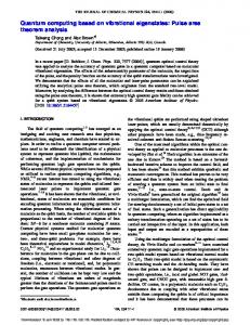
Figure 1 | (a) Structure of a singly charged QD inside a double-sided optical microcavity with circular cross-section. (b) Energy-level scheme of a singly charged QD inside a double-sided optical microcavity with the polarization allowed transition rules for the coupling photons27,32. | Ræ ( | Læ) represents a right-circularly (left-circularly) polarized photon.
make an electron spin in a QD an excellent candidate for the qubit in solid-state quantum computation. In 2008, Hu et al.26,27 proposed a device, an excess electron confined in a self-assembled In(Ga)As QD or a GaAs interface QD placed inside a single-sided or a double-sided optical resonant cavity. Many interesting tasks have been carried out on this quantum system28–40. For example, utilizing this system, Hu et al.28,29 built a controlled-phase gate with a polarization photon as the control qubit and an electron spin as the target qubit. Bonato et al.32 constructed a hybrid CNOT gate with an electron spin as the control qubit and a polarization photon as the target qubit. Also, a hybrid CNOT gate with a polarization photon as the control qubit and an electron spin as the target qubit was proposed recently33. In 2013, Ren et al.34 proposed a scheme for a photonic spatial-polarization hyper-controlled-not gate assisted by a QD inside a one-sided optical microcavity. In 2014, Ren and Deng35 presented a scheme for the hyper-parallel photonic quantum computation with coupled QDs. The scheme for the CNOT gate on two photonic qubits36 was presented in 2013. A scheme37 for entanglement purification and concentration of electron-spin entangled states and a quantum repeater scheme38 based on QD spins in optical microcavities were introduced in 2011 and 2012, respectively. In this paper, we investigate the possibility to achieve a compact and scalable quantum computing based on stationary electron-spin qubits. We construct two important universal quantum gates on electron-spin systems, including the two-qubit CNOT gate and the three-qubit Toffoli gate, by using the giant optical circular birefringence induced by the electron spins in QDs confined in double-sided optical microcavities as a result of cavity quantum electrodynamics (QED). We give the compact quantum circuits and the detailed processes for implementing these universal quantum gates. The qubits of our gates are encoded on two orthogonal electron-spin states of the excess electrons confined in QDs inside optical resonant microcavities, denoted by j "æ and j #æ. A polarized single photon, denoted by jRæ or jLæ, plays a medium role. After the input-output process of the single photon, the measurement on the polarization of the output photon and some proper single-qubit operations are performed on the electron-spin qubits, the evolutions of these universal quantum gates are accomplished with the probability of 100% in principle. Our protocols have some features. First, our quantum circuits for the universal quantum gates are compact and economic, and they reduce the resources needed and the errors as they do not require additional electron-spin qubits, just a flying photon. Second, SCIENTIFIC REPORTS | 4 : 7551 | DOI: 10.1038/srep07551
the double-sided QD-cavity system easily reaches a large phase difference (p) between the uncoupled cavity and the coupled cavity27, while it is a hard work in a single-sided QD-cavity system. Third, our gates allow for a scalable and stable quantum computing as the qubits for the gates are confined in solid-state quantum systems. Fourth, our schemes work in a deterministic way if the photon loss caused by the optical elements (such as half-wave plates, and polarizing beam splitters) and the detection inefficiency are negligible. Fifth, our schemes are feasible with current technology. Both a high fidelity and a high efficiency for each gate can be achieved when the ratio of the side leakage to the cavity decay is low.
Results Giant optical circular birefringence. We exploit the optical property26–29 of the QD-cavity system to complete our schemes for implementing the CNOT gate and the Toffoli gate on electron spins. The chematic diagram for a QD-cavity system, a singly charged In(Ga)As QD or a GaAs interface QD placed at the antinode of a resonant double-sided optical microcavity with two symmetric and low loss partially reflective mirrors in the top and the bottom27, employed in our protocols, is shown in Fig. 1(a). The negatively charged exciton (trion, X2), which consists of two electrons and one heavy hole41, is the fundamental optical excitation, and it is essential for optical transitions in a QD-cavity system. There are two kinds of spin-dependent optical transitions, shown in Fig. 1(b). The photon in the state jR"æ or jL#æ (sz 5 11) couples to the dipole for the transition from j "æ to j "#Xæ, and the photon in the state jR#æ or jL"æ (sz 5 21) couples to the dipole for the transition from j #æ to j #"Yæ. Here the superscript arrows of jRæ (jLæ) indicate their propagation direction of the photon along the normal direction of the cavity z axis and the circular polarization of the photons are dependent of their propagation direction. j Xæ and j Yæ represent the �two heavy-hole � spin � � states with the z-direction spin projections � 3 � 3 �z � � 2 and �{ 2 , respectively. j "æ and j #æ represent the � � � 1 electron-spin states with the z-direction spin projections ��z 2 � � � 1 and ��{ , respectively. 2 The change of the input photon state in the QD-cavity system can be obtained by solving the Heisenberg equations of motion for a QDcavity system42 2
www.nature.com/scientificreports h pffiffiffi pffiffiffi d^a ks i ^ ~{ iðvc {vÞzkz ^a{gs{ { k^ain { k^a’in zH, 2 dt h ds{ ci ^ ~{ iðvX { {vÞz s{ {gsz ^azG, dt 2 and the input-output relation for the cavity pffiffiffi pffiffiffi ^ar ~^ain z k^a, ^at ~^a’in z k^a:
ð1Þ
ð2Þ
The specific expression of the reflection and the transmission coefficients of a realistic QD-cavity system is27:
� � {k iðvX { {vÞz 2c � � � r ðvÞ~1zt ðvÞ, t ðvÞ~ � : ð3Þ iðvX { {vÞz 2c iðvc {vÞzkz k2s zg2
Here, vc, v, and vX { are the frequencies of the cavity, the input a and s2 are the cavity photon, and the X2 transition, respectively. ^ field operator and the X2 dipole operator, respectively. g is the coupling strength between X2 and the cavity mode. k, ks/2, and c/2 are the cavity decay rate, the side leakage (unwanted absorption) rate, and the dipole decay rate, respectively. ^ain and ^a’in are the two input field ^ ^ and G operators, and ^ar and ^at are the two output field operators. H are the noise operators related to reservoirs. Æszæ < 21 is taken for a weak excitation approximation. The complex reflection (transmission) coefficient given by Eq.(3) indicates that the reflected (transmitted) light encounters a phase shift. When the QD is in the state j "æ, the jR"æ or jL#æ light feels the hot cavity (g ? 0) and gets a phase shift Qh with the flip of the photon polarization and the photon propagation direction after reflection, whereas the jL"æ or jR#æ light feels the cold cavity (g 5 0) and gets a phase shift Q0 with the photon polarization and the photon propagation direction unchanged after transmission. In the case that the QD is in the state j #æ, the jR"æ or jL#æ light feels the cold cavity and gets a phase shift Q0 after transmission, whereas the jL"æ or jR#æ light feels the hot cavity and gets a phase shift Qh after reflection. The phase shift Qh or Q0 can be adjusted by the frequency detuning v{v0 ðvc ~vX { ~v0 Þ. When considering the interaction with vX { ~vc ~v, that is, the QD is resonant with the cavity and the spin of the independent electron is connected by the resonant single photon, the reflection and the transmission coefficients for the uncoupled cavity (called a cold cavity, g50) and the coupled cavity (called a hot cavity, g ? 0) can be simplified as r0 ~
ks 2
kz k2s
,
t0 ~{
k , kz k2s
r~1zt,
target qubit if and only if (iff) the control qubit is in j #æ. That is, 0 1 I2 0 0 B C ð6Þ CNOT~@ 0 0 1 A 0 1 0 in the basis {j ""æ, j "#æ, j #"æ, j ##æ}. Here I2 is a 2 3 2 identity matrix. Suppose the two remote electrons confined in cavities 1 and 2 are initially prepared in the state � 1 � ð7Þ jyin ict ~ pffiffiffi j:ic zj;ic 6 cosaj:it zsinaj;it : 2 The subscript c represents the control qubit confined in cavity 1 and t stands for the target qubit confined in cavity 2. Our schematic diagram for a CNOT gate on the two stationary electron-spin qubits is shown in Fig. 2. The input single photon in the state jR#æ transmits the polarizing beam splitter in the circular basis CPBS1 to the spatial mode 1 and injects into cavity 1 which � � � � cavity induces the transformations �R; 1 j:ic ? {�R; 2 j:ic and � ;� � :� �R j;i cavity � c ? L 1 j;ic . The subscript i (i~1,2, � � � ,) of jRæ (jLæ) 1 represents the spatial mode i from which the photon is emitted. CPBS can be constructed by a PBS in the horizontal and vertical basis followed by a half-wave plate (HWP) at 22.5u. Subsequently, the photon in the state jR#æ2 or jL"æ1 is led to the spatial mode 3 by � � CPBS1 � � CPBS1 which completes the transformations �R; 2 ? �R; 3 and � : � CPBS1 � : � �L ? �L 3 . That is, rounda transforms the state of the whole 1 system composed of the two excess electrons inside cavities 1 and 2 and the single photon from the initial state jy0æ to jy1æ. Here � � ð8Þ jy0 i~�R; 6jyin ict , �� � � 1 � � jy1 i~ pffiffiffi {�R; 3 j:ic z�L: 3 j;ic cos aj:it zsin aj;it : 2
ð9Þ
c k t~{ c � 2 ks � 2 : ð4Þ kz 2 2 zg
r0 R 0 and t0 R 21 for the uncoupled cavity, and t R 0 and r R 1 for the coupled cavity can be achieved in the strong coupling regime g . (k, c) in experiment by adjusting jv 2 v0j , k when ks =k (the ideal cavity) and c 5 0.1k. That is, if the photon couples to X2, it will be reflected by the cavity and both the propagation and the polarization of the photon are flipped. If the photon does not couple to X2, it will transmit the cavity and acquire a p mod 2p phase shift relative to a reflected one27,32. Therefore, the rules of the input photon can be summarized as follows32: � : � � ; � � � � � � � � � � � � � �R : ?�L : , �L: : ?{�L: : , �R; : ?{�R; : , �L; : ?�R: : , � : � � : � � : � � ; � � ; � � : � � � � � ð5Þ �R ; ?{�R ; , �L ; ?�R ; , �R ; ?�L ; , �L; ; ?{�L; ; :
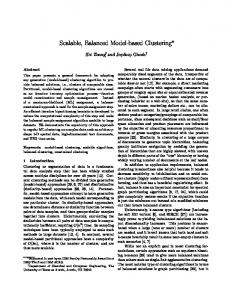
The photon spin sz remains unchanged upon the reflection as the circular polarization of the photons is dependent of their propagation direction, so jR"æ and jL#æ with the same sz 5 11, jL"æ and jR#æ with sz 5 21. Compactly implementing CNOT gate on a two-qubit electronspin system. Now, let us describe the construction of a deterministic CNOT gate on the two stationary electron-spin qubits assisted by double-sided QD-cavity systems. It flips the SCIENTIFIC REPORTS | 4 : 7551 | DOI: 10.1038/srep07551
Figure 2 | Schematic diagram for compactly implementing a CNOT gate on two electron-spin qubits in optical microcavities. The electron spin in cavity 1 is the control qubit and that in cavity 2 is the target qubit. CPBSi (i 5 1, 2) is a polarizing beam splitter (PBS) in the circular basis { | Ræ, | Læ}, which transmits the right-circularly polarized photon | Ræ and reflects the left-circularly polarized photon | Læ, respectively. CPBS can be constructed by a PBS in the horizontal and vertical basis followed by a quarter-wave plate or a half-wave plate (HWP) whose optical axis is set at 22.5u. Here HWP is used to implement a Hadamard (Hp) operation on the polarization photon passing through it. Pp is a phase shifter which contributes a p phase shift on the photon passing through it. D1 and D2 are two single-photon detectors. 3
www.nature.com/scientificreports The transformations of rounda can be described by the following unitary matrix: 0 1 {1 0 0 0 B 0 0 0 1C B C ð10Þ Urounda ~B C @ 0 0 {1 0 A 0
1
0
0
in the basis {jR#æj "æ, jR#æj #æ, jL"æj "æ, jL"æj #æ}. Before the photon in the state jR#æ3 or jL"æ3 arrives at CPBS2 simultaneously, a Hadamard operation Hp is performed on it (i.e., let it pass through the HWP whose optical axis is set at 22.5u) and an He operation is performed on the excess electron inside cavity 2 before and after the photon interacts with the QD in cavity 2. Here an Hp operation completes the transformations Hp
jRi ? p1ffiffi2 ðjRizjLiÞ,
Hp
jLi ? p1ffiffi2 ðjRi{jLiÞ,
ð11Þ
and an He operation completes the transformations He
j:i ? p1ffiffi2 ðj:izj;iÞ,
He
j;i ? p1ffiffi2 ðj:i{j;iÞ:
ð12Þ
The operations (Hp, He R roundb R He) induce the state of the whole system to be 1 � � � � � � jy2 i~{ �R; 8 z�L: 8 j:ic cos aj:it zsin aj;it 2 ð13Þ 1 � � � � � � z �R; 8 {�L: 8 j;ic cos aj;it zsin aj:it : 2 Here roundb completes the transformation � ;� � � � � roundb � � b �R j:i round ? �R; 8 j:i, �R; 4 j;i ? �L: 8 j;i, 4 � :� � � � � roundb � � b �L j:i round ? �L: j:i, �L: j;i ? �R; j;i: 4
8
4
ð14Þ
8
From Eq.(13), one can see that if the output photon is in the state jLæ, the CNOT gate is accomplished. If the output photon is in the state jRæ, after a feed-forward single-qubit operation 2sz 5 2j "æ Æ" j 1 j #æ Æ# j is performed on the QD in cavity 1, the CNOT gate is accomplished as well. That is, after the measurement on the output photon and the feed-forward operation on the QD, the state of the two-electron system becomes j;i � j:i � jyout ict ~ pffifficffi cos aj:it zsin aj;it z pffifficffi cos aj;it zsin aj:it : ð15Þ 2 2 Therefore, the quantum circuit shown in Fig. 2 converts the input CNOT
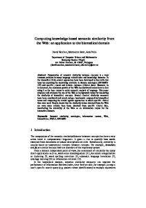
state jyinæct to the output state jyoutæct, i.e., jyin ict ? jyout ict . It implements a deterministic electron-spin CNOT gate which flips the state of the target electron-spin qubit when the control electron-spin qubit is in the state j #æ; otherwise, nothing is done on the target qubit. Toffoli gate on a three-qubit electron-spin system. The schematic diagram of our scheme for compactly implementing a three-qubit electron-spin Toffoli gate is shown in Fig. 3. It implements a NOT operation on the target qubit iff both the two control qubits are in j #æ. That is, the unitary transformation of the Toffoli gate on the three QDs can be characterized by the following matrix 0 1 I6 0 0 B C Tof f oli~@ 0 0 1 A ð16Þ 0 1 0 in the basis {j """æ, j ""#æ, j "#"æ, j "##æ, j #""æ, j #"#æ, j ##"æ, j ###æ}. Here I6 is a 6 3 6 identity matrix. Suppose the spins of the three excess electrons in cavities 1, 2, and 3 are encoded as the first control, the second control, and the target qubits, respectively. The system SCIENTIFIC REPORTS | 4 : 7551 | DOI: 10.1038/srep07551
Figure 3 | Schematic diagram for compactly implementing a deterministic Toffoli gate on three electron-spin qubits, assisted by QDcavity systems. The electron spins in cavities 1 and 2 are the two control qubits c1 and c2, and the spin in cavity 3 is the target qubit t. DL is a timedelay device which makes the photon emitting from the spatial mode 4 interfere with the photon emitting from the spatial mode ~2 at the 50550 beam splitter (BS). The polarizing beam splitter in the {6} circular basis (62PBS’) transmits pffiffiffithe diagonal-polarization photon jzi~ðjRizjLiÞ=pffiffi2ffi and reflects the antidiagonal-polarization photon j{i~ðjRi{jLiÞ= 2, respectively.
composed of those three electrons is initially prepared in the state � � � 1
1
jJin ic1 c2 t ~ pffiffiffi j:ic1 zj;ic1 6 pffiffiffi j:ic2 zj;ic2 6 cos aj:it zsin aj;it :ð17Þ 2 2
Our protocol for a Toffoli gate can be achieved with three steps discussed in detail as follows. First, a single photon in the state jR#æ is injected into the input port, shown in Fig. 3. If the photon is transmitted through � � cavity 1, it is emitted from the spatial mode ~1 with the state {�R; ~1 . If the photon is reflected by cavity 1, it is emitted from the spatial mode 1 with the state jL"æ1. The nonlinear interaction between the input photon and the QD in cavity 1 transforms the state of the composite system composed of the three electrons (c1, c2 and t) and the single photon into jJ1 i~
�
�� � � 1 �� ; � { R ~1 j:ic1 z�L: 1 j;ic1 j:ic2 zj;ic2 cos aj:it zsin aj;it : ð18Þ 2
When the photon is emitted from the spatial mode 1, it will be injected into rounda1 described by Eq.(10). When the photon is emitted from the spatial mode ~1, it will be injected into rounda2 described by Eq.(10). Rounda1 and rounda2 transform the state of the whole system into 4
www.nature.com/scientificreports �� � � j:ic1 � ; � �R j:i {�L: j;i cos aj:it zsin aj;it ~2 ~2 c2 c2 2 ð19Þ �� � ;� j;ic1 � : � � � { L 2 j:ic2 { R 2 j;ic2 cos aj:it zsin aj;it : 2
jJ2 i~
The photon emitting from the spatial mode ~2 does not interact with the QD in cavity 3, while the photon emitting from the spatial mode 2 is injected into cavity 3. Before and after the photon emitting from the spatial mode 2 interacts with the QD in cavity 3, an Hp is performed on it with HWP1 and HWP2, and an He is performed on the electron in cavity 3, respectively. Operations (HWP1, He R rounda3 R HWP2, He) transform the state of the whole system into � � � � � 1 � � jJ3 i~ �R; ~2 j:ic1 j:ic2 {�L: ~2 j:ic1 j;ic2 z�L: 4 j;ic1 j:ic2 2 ð20Þ � 1� � � cos aj:it zsin aj;it { �R; 4 j;ic1 j;ic2 cos aj;it zsin aj:it : 2 Second, the photon emitting from the spatial mode 4 interferes with the photon emitting from the spatial mode ~2 at the 50550 beam splitter (BS) which completes the transformations � � BS BS jRi4 ? p1ffiffi2 jRi5 zjRi~3 , jLi4 ? p1ffiffi2 jLi5 zjLi~3 , ð21Þ � � BS BS jRi~2 ? p1ffiffi2 jRi5 {jRi~3 , jLi~2 ? p1ffiffi2 jLi5 {jLi~3 : Third, the output n .pffiffiffiophoton is measured in the basis j+i~ðjRi+jLiÞ 2 . After some feed-forward single-qubit operations are performed on the electron-spin qubits, a Toffoli gate on the three-qubit electron-spin system is achieved. That is, the state of the system composed of the three electrons confined in QDs becomes � 1
jJout ic1 c2 t ~ j:ic1 j:ic2 zj:ic1 j;ic2 zj;ic1 j:ic2 2 ð22Þ � 1 � cos aj:it zsin aj;it z j;ic1 j;ic2 cos aj;it zsin aj:it : 2
Figure 4 | The fidelities of the present deterministic scalable universal quantum gates on electron-spin systems vs the coupling strength g/k and the side leakage rate ks/k. (a) The fidelity of the CNOT gate FCT; (b) the fidelity of the Toffoli gate FT. vc ~vx{ ~v and c 5 0.1k are taken for (a) and (b) as c is about several meV in experiment. SCIENTIFIC REPORTS | 4 : 7551 | DOI: 10.1038/srep07551
Here, the response of detector D2 indicates that the Toffoli gate is successful. The response of detector D1 indicates that the feed-forward single-qubit operations 2sz and sz should be performed on the QDs in cavities 1 and 2, respectively. The response of detector D3 (D4) indicates that sz should be performed on the QD in cavity 2 (1). From Eq.(22), one can see that the quantum circuit shown in Fig. 3 converts the input state jJin ic1 c2 t to the output state jJout ic1 c2 t , i.e., Toff oli
jJin ic1 c2 t ? jJout ic1 c2 t . That is, it can be used to implement a Toffoli gate on a three-qubit electron-spin system, which flips the state of the target electron-spin qubit iff both the two control electron-spin qubits are in the state j #æ, in a deterministic way.
Discussion We have discussed the construction of universal quantum gates on electron-spin qubits, assisted by double-sided optical microcavities. In above discussion, all the QD-cavity systems are ideal. That is, the side leakage of the cavities is not taken into account. However, there inevitably exists the side leakage (which includes the material background absorption and the cavity loss) in a realistic QD-cavity system, which induces the polarize-bit-flip errors and different amplitudes between the coupled and the uncoupled photons. If the cavity leak is taken into account, the optical selection rules employed in our work become27,32 � ; � � � � � : � � � � � � �R ; ?jr j�L: ; zjt j�R; ; , �L ; ?jr j�R; ; zjt j�L: ; , � ; � � ; � � : � � : � � : � � �ð23Þ �R : ?{jt0 j�R : {jr0 j�L : , �L : ?{jt0 j�L : {jr0 j�R; : : QDs inside microcavities with high quality factors Q are of particular interest for studying light-matter interaction. The photon loss strongly reduces Q. In micropillar microcavities, a drop of Q takes place with the pillar diameter d due to an increasing photon loss43. It is desired to increase the Q values but maintain a small effective optical mode volume, which can be achieved by improving the sample design, growth, and structure43. Some coupling strengths and the quality factors of the QD-cavity system have been experimentally achieved in various microcavities and nanocavities43–47 (see Tab. 1). Quantum logic gates play an important role in quantum computing. The feasibilities of realizing universal quantum computation with superconducting qubits in circuit-quantum-electrodynamics setups have been investigated48,49. Romero et al.48 proposed a scheme for realizing an ultrafast controlled-phase gate in current circuitQED technology at subnanosecond time scales with the fidelity of the gate F 5 99%. Stojanovic´ et al.49 designed a quantum circuit for directly and fast realizing a Toffoli gate on superconducting qubits within 75 ns with F . 90%, and within 140 ns with F . 99%. Based on specific solid-state platforms, proposals for realizing the CNOT pffiffiffiffiffiffiffiffiffiffiffiffiffi and SWAP (SWAP) gates in two-qubit Heisenberg spin chains have been proposed50–52. In our work, the schemes for quantum gates based on the electron spins in QDs are particularly interesting because of their good scalability and long coherence time which can be extended from T2 , ns range14–16 to T2 , ms range using the spin echo technique. The weakexcitation approximation is taken in QD-cavity systems, and it demands the number of the intracavity photons less than the number of the critical photons53 n0 5 c2/2g2. That is to say, the time interval between two intracavity photons should be longer than t/n0 , ns (By taking g/(k 1 ks) 5 1.0, ks/k 5 0.7 and c 5 0.1k for a micropillar microcavity with diameter d 5 1.5 m m, Q 5 1.7 3 104, one can get n0 5 2 3 1023, t 5 9 ps, and t/n0 5 4.5 ns). Here t is the cavity photon lifetime and it is around 10 ps. In our schemes, we need only one single photon. The speed of the photon interacting with the electronspin is determined by the cavity photon lifetime. Moreover, the photon medium is easy to be controlled and manipulated. In summary, we have proposed two deterministic schemes for compactly implementing a set of universal quantum gates on stationary electron-spin qubits, including the two-qubit CNOT gate 5
www.nature.com/scientificreports
Table 1 | The quality factors and coupled strengths of the QD-cavity systems have been achieved in experiments29,43,44,47 coupled strength
quality factor
parameters
g=ðkzks Þ^0:5 g=ðkzks Þ^2:4 g=ðkzks Þ^0:8 g=ðkzks Þ^1:0
Q , 8800 Q , 4 3 104 Q , 6.5 3 104 Q^1:7|104
d , 1.5 mm44 d , 1.5 mm,43 d , 7.3 mm47 d , 1.5, k=ks ^0:729
and three-qubit Toffoli gate. Our universal quantum gates are scalable. Different to the hybrid schemes26–29,32 acting on the photon-electron qubits, our schemes are based on solid-state systems (QD-cavity systems). Moreover, our schemes do not require additional electron-spin qubits. Comparing with the synthesis of gates in terms of CNOT gate, our scheme for Toffoli gate is powerful. It is required 6 CNOT gates to synthesize a Toffoli gate in the best case12. It is worth pointing out that with the present technology, our schemes are feasible. Both high fidelities and high efficiencies can be achieved when the ratio of the side leakage to the cavity decay is low. With universal quantum gates on electron-spin qubits, scalable quantum computing can be achieved. Maybe it is interesting to investigate some important quantum algorithms based on electron-spin systems in future.
Methods Manipulation and measurement of the QD spin. The QD-spin superposition state can be prepared by performing single spin-qubit rotations with picosecond optical pulses22,23 or nanosecond electron-spin resonance (ESR) microwave pulses in an external magnetic field14,15 on the spin eigenstate which is prepared by an optical pumping or optical cooling19,20. Ultrafast optical coherent manipulation of a QD-spin qubit has been demonstrated in a picosecond or femtosecond time scale22,24, and an ultrafast p/2 spin rotation can be used to complete a Hadamard operation on a spin qubit. In our schemes, the spin level levels of X2 are in degeneracy as the anisotropic
electron-hole exchange interaction, which lifts the degeneracy of the neutral exciton54,55, vanishes for the charged excitons in self-assembled QDs. The ESR-based (Faraday geometry) and coherent optical (geometric phase or AC stark shift) QD spin manipulation require an application of a magnetic field which lifts the sublevels of the QD spin, and the degeneracy transition rules given by Eq.(5) are not valid any more as the R- and L-polarized transitions have a small energy difference. In our schemes, the single-qubit operations are performed on the QDs before or after the single photon interacts with the QDs, so the single photon can interact with the QDs in the absence of the external magnetic field. This trick might be employed to overcome above drawback. Experimentally demonstrating this trick is a challenge with current experimental technology as the required magnetic-relaxation timescales , ms is a challenge, and the accurate control of the switch on the required timing needs to be considered. Furthermore, the electron coherence time without a magnetic field is much shorter than that in the presence of a magnetic field (another possible solution to achieve the degeneracy transitions in an external magnetic field is to employ the QDs with the identical g factors of the electron and hole). From the rules given by Eq.(5), one can see that a single photon can be used to complete a 180u spin rotation of the QD around the optical axis and detect the polarization of the QD spin. Take the jR#æ light as an example, the nonlinear interaction between such a single photon and the QD induces the transformation � ;� � � � � �R ðaj:izbj;iÞ?{a�R; j:izb�L: j;i: ð24Þ The single photon in the state jRæ (jLæ) indicates that the QD is in the state j "æ (j #æ). The average fidelities of the gates. In our work, the fidelity of a universal quantum gate is defined as F 5 jÆYrjYiæj2. Here jYræ presents the finial state in a realistic QD-cavity system composed of excess electrons encoded for the gates and a single photon medium, whereas jYiæ represents the final state of this composite system in the ideal condition. The reflection and transmission coefficients of the QD-cavity system for a realistic system given by Eqs.(4) and (7) affect the fidelities of our universal quantum gates. Taking the CNOT gate as an example, the average fidelity of the CNOT gate is given by ð 1 2p F�CT ~ dajhyr jyi ij2 : ð25Þ 2p 0 From above discussion, one can see that the output state of our scheme for the CNOT gate in the ideal case jyiæ can be expressed as jþi � j�i � jyi i~ pffiffiffi cos aj;ic j;it zsin aj;ic j:it { pffiffiffi cos aj:ic j:it zsin aj:ic j;it : 2 2
ð26Þ
If we consider each input-output process of our scheme in the real case described by Eq.(23), the output state of our scheme for the CNOT gate can be rewritten as jzi � jyr i~ pffiffiffi jt jðj cos azf sin aÞj;ic j:it zjt jðf cos azj sin aÞj;ic j;it 2 2 � {jt0 jðj cos azf sin aÞj:ic j:it {jt0 jðf cos azj sin aÞj:ic j;it
ð27Þ
� � � j�i � z pffiffiffi jr jj;ic cos aj;it zsin aj:it {jr0 jj:ic cos aj;it zsin aj:it 2 with j 5 (jt0j 2 jr0j) 2 (jtj 2 jrj) and f 5 (jt0j 2 jr0j) 1 (jtj 2 jrj). The efficiencies of the gates. The efficiency of a quantum gate is defined as the yield of the photons (g 5 noutput/ninput), that is, the ratio of the number of the output photons noutput to that of the input photons ninput. It is also sensitive to the reflection and transmission coefficients of the QD-cavity system. The efficiencies of the CNOT gate and Toffoli gate can be respectively expressed as
Figure 5 | The efficiencies of the present universal quantum gates vs the coupling strength g/k and the side leakage rate ks/k. (a) The efficiency of the CNOT gate gCT; (b) the efficiency of the Toffoli gate gT. vc ~vx{ ~v and c 5 0.1k are taken for (a) and (b). SCIENTIFIC REPORTS | 4 : 7551 | DOI: 10.1038/srep07551
gCT ~ð1{jt0 jjr0 j{jt jjr jÞ2 ,
ð28Þ
1 gT ~ ð1{jt0 jjr0 j{jt jjr jÞ2 ð2{jt0 jjr0 j{jt jjr jÞÞ: 2
ð29Þ
Fidelity and efficiency estimation. The average fidelities F and the efficiencies g of the present universal quantum gates as the function of the coupling strength g/k and the side leakage rate ks/k are shown in Figs. 4 and 5, respectively. These results indicate that the fidelity and the efficiency behaviors of the two gates are similar to each other. When ks/k is very small and g/k is large, the fidelities and the efficiencies
6
www.nature.com/scientificreports of the gates are close to one. Both the fidelities and the efficiencies are high in both the strong coupling regime [g . (k, c)] and the weak coupling regime [g , (k, c)] when the ratio of the side leakage to the cavity decay is low. However, with an increase ks/k or a decrease g/k, the fidelities and the efficiencies of the gates declines. Here the fidelities and the efficiencies of the single-qubit operations performed on the photons or the QDs in our schemes are unity, that is, the imperfect operation and the photon loss in the single-qubit operations are taken into account. To get high fidelities and efficiencies of the gates, a small side leakage is required, and it can be achieved by improving the sample growth and optimizing etch processing43. ks/k 5 0.05 may be achieved for a Q , 165000 pillar microcavity43 and reduce Q to , 9000 by decreasing the reflection of the top mirror26. For a QD-cavity system, g=ðkzks Þ^0:5, g/k 5 2.4, and g=ðkzks Þ^0:8 have been observed in experiment43,44,47. For our protocols, when g/k 5 2.4 and ks/k 5 0.2, FCT 5 0.981517 and FT 5 0.983317 with gCT 5 0.82597 and gT 5 0.788322, respectively. If the cavity side leakage is negligible, the average fidelities of our quantum gates are close to one with a near-unity success probability (FCT 5 0.999916, FT 5 0.999857, gCT 5 0.98301, gT 5 0.978816 when ks 5 0). Here the subscripts CT and T represent our CNOT gate and Toffoli gate, respectively. The fidelities of aforementioned universal quantum gates are decreased by a amount of 1 2 exp(2t/T2) due to the exciton dephasing effect caused by the exciton decoherence27. That is, the fidelity depends on the X2 coherence time T2 and the cavity photon coherence time t. Since the information of the polarization photon is transferred to the electron through the excitonic state, the exciton dephasing affects the state of the electron. The exciton dephasing only reduces the fidelity by a few percents due to the optical dephasing caused by population relaxation or the loss of phase coherence among the dipoles and the spin dephasing caused by spin interactions with the surrounding nuclei in self-assemble In(Ga)As-based QDs. The optical coherence time of excitons T2 can be in several hundreds of picoseconds range at low temperature while the cavity photon lifetime t is much shorter than the cavity photon lifetime 10 ps (Q: 104 – 105)56–58. The coherence time of a QD-hole spin T2h is longer than 100 ns59 and it is at least three orders of magnitude longer than the cavity photon lifetime t , 10 ps, so it can be neglected. Besides the exciton dephasing, a few percent heavy-light hold mixing in the valence reduces the fidelity by a few percents60. This effect can be reduced by improving the sample design and choosing different types of QDs. 1. Barenco, A. et al. Elementary gates for quantum computation. Phys. Rev. A 52, 3457–3467 (1995). 2. Gershenfeld, N. A. & Chuang, I. L. Bulk spin-resonance quantum computation. Science 275, 350–356 (1997). 3. Knill, E., Laflamme, R. & Milburn, G. J. A scheme for efficient quantum computation with linear optics. Nature 409, 46–52 (2001). 4. Feng, G., Xu, G. & Long, G. Experimental realization of nonadiabatic Holonomic quantum computation. Phys. Rev. Lett. 110, 190501 (2013). 5. Hua, M., Tao, M. J. & Deng, F. G. Universal quantum gates on microwave photons assisted by circuit quantum electrodynamics. Phys. Rev. A 90, 012328 (2014). 6. Vidal, G. & Dawson, C. M. Universal quantum circuit for two-qubit transformations with three controlled-NOT gates. Phys. Rev. A 69, 010301 (2004). 7. Vatan, F. &Williams, C. Optimal quantum circuits for general two-qubit gates. Phys. Rev. A 69, 032315 (2004). 8. Shende, V. V., Markov, I. L. & Bullock, S. S. Minimal universal two-qubit controlled-NOT-based circuits. Phys. Rev. A 69, 062321 (2004). 9. Shende, V. V., Bullock, S. S. & Markov, I. L. Recognizing small-circuit structure in two-qubit operators. Phys. Rev. A 70, 012310 (2004). 10. Nielsen, M. A. & Chuang, I. L. Quantum Computation and Quantum Information (Cambridge University Press, Cambridge, 2000). 11. Shi, Y. Y. Both Toffoli and controlled-not need little help to do universal quantum computation. Quant. Inf. Comput. 3, 084–092 (2003). 12. Shende, V. V. & Markov, I. L. On the CNOT-cost of Toffoli gate. Quant. Inf. Comput. 9, 0461–0468 (2009). 13. Loss, D. & DiVincenzo, D. P. Quantum computation with quantum dots. Phys. Rev. A 57, 120 (1998). 14. Petta, J. R. et al. Coherent manipulation of coupled electron spins in semiconductor quantum dots. Science 309, 2180–2184 (2005). 15. Greilich, A. D. et al. Mode locking of electron spin coherences in singly charged quantum dots. Science 313, 341–345 (2006). 16. Press, D. et al. Ultrafast optical spin echo in a single quantum dot. Nat. Photo. 4, 367–370 (2010). 17. Ciorga, M. et al. Addition spectrum of a lateral dot from Coulomb and spinblockade spectroscopy. Phys. Rev. B 61, R16315(R) (2000). 18. Elzerman, J. M. et al. Few-electron quantum dot circuit with integrated charge read out. Phys. Rev. B 67, 161308(R) (2003). 19. Atatu¨re, M. et al. Quantum-dot spin-state preparation with near-unity fidelity. Science 312, 551–553 (2006). 20. Atatu¨re, M., Dreiser, J., Badolato, A. & Imamoglu, A. Observation of Faraday rotation from a single confined spin. Nat. Phys. 3, 101–106 (2007). 21. Hanson, R. et al. Single-shot readout of electron spin states in a quantum dot using spin-dependent tunnel rates. Phys. Rev. Lett. 94, 196802 (2005). 22. Berezovsky, J., Mikkelsen, M. H., Stoltz, N. G., Coldren, L. A. & Awschalom, D. D. Picosecond coherent optical manipulation of a single electron spin in a quantum dot. Science 320, 349–352 (2008).
SCIENTIFIC REPORTS | 4 : 7551 | DOI: 10.1038/srep07551
23. Press, D., Ladd, T. D., Zhang, B. Y. & Yamamoto, Y. Complete quantum control of a single quantum dot spin using ultrafast optical pulses. Nature 456, 218–221 (2008). 24. Gupta, J. A., Knobel, R., Samarth, N. & Awschalom, D. D. Ultrafast manipulation of electron spin coherence. Science 292, 2458–2461 (2001). 25. Chen, P. C., Piermarocchi, C., Sham, L. J., Gammon, D. & Steel, D. G. Theory of quantum optical control of a single spin in a quantum dot. Phys. Rev. B 69, 075320 (2004). 26. Hu, C. Y., Young, A., O’Brien, J. L., Munro, W. J. & Rarity, J. G. Giant optical Faraday rotation induced by a single-electron spin in a quantum dot: Applications to entangling remote spins via a single photon. Phys. Rev. B 78, 085307 (2008). 27. Hu, C. Y., Munro, W. J., O’Brien, J. L. & Rarity, J. G. Proposed entanglement beam splitter using a quantum-dot spin in a double-sided optical microcavity. Phys. Rev. B 80, 205326 (2009). 28. Hu, C. Y., Munro, W. J. & Rarity, J. G. Deterministic photon entangler using a charged quantum dot inside a microcavity. Phys. Rev. B 78, 125318 (2008). 29. Hu, C. Y. & Rarity, J. G. Loss-resistant state teleportation and entanglement swapping using a quantum-dot spin in an optical microcavity. Phys. Rev. B 83, 115303 (2011). 30. Brunner, N., Young, A. B., Hu, C. Y. & Rarity, J. G. Proposal for a loophole-free Bell test based on spin-photon interactions in cavities. New J. Phys. 15, 105006 (2013). 31. Young, A. B., Hu, C. Y. & Rarity, J. G. Generating entanglement with low-Q-factor microcavities. Phys. Rev. A 87, 012332 (2013). 32. Bonato, C. et al. CNOT and Bell-state analysis in the weak-coupling cavity QED regime. Phys. Rev. Lett. 104, 160503 (2010). 33. Wei, H. R. & Deng, F. G. Universal quantum gates for hybrid systems assisted by quantum dots inside double-sided optical microcavities. Phys. Rev. A 87, 022305 (2013). 34. Ren, B. C., Wei, H. R. & Deng, F. G. Deterministic photonic spatial-polarization hyper-controlled-not gate assisted by a quantum dot inside a one-side optical microcavity. Laser Phys. Lett. 10, 095202 (2013). 35. Ren, B. C. & Deng, F. G. Hyper-parallel photonic quantum computation with coupled quantum dots. Sci. Rep. 4, 4623 (2014). 36. Wei, H. R. & Deng, F. G. Scalable photonic quantum computing assisted by quantum-dot spin in double-sided optical microcavity. Opt. Express 21, 17671–17685 (2013). 37. Wang, C., Zhang, Y. & Jin, G. S. Entanglement purification and concentration of electron-spin entangled states using quantum-dot spins in optical microcavities. Phys. Rev. A 84, 032307 (2011). 38. Wang, T. J., Song, S. Y. & Long, G. L. Quantum repeater based on spatial entanglement of photons and quantum-dot spins in optical microcavities. Phys. Rev. A 85, 062311 (2012). 39. Ren, B. C., Wei, H. R., Hua, M., Li, T. & Deng, F. G. Complete hyperentangledBell-state analysis for photon systems assisted by quantum-dot spins in optical microcavities. Opt. Express 20, 24664–24677 (2012). 40. Wang, T. J., Lu, Y. & Long, G. L. Generation and complete analysis of the hyperentangled Bell state for photons assisted by quantum-dot spins in optical microcavities. Phys. Rev. A 86, 042337 (2012). 41. Warburton, R. J. et al. Charged excitons in self-assembled semiconductor quantum dots. Phys. Rev. Lett. 79, 5282 (1997). 42. Walls, D. F. & Milburn, G. J. Quantum Optics (Springer-Verlag, Berlin, 1994). 43. Reitzenstein, S. et al. AlAs/GaAs micropillar cavities with quality factors exceeding 150.000. Appl. Phys. Lett. 90, 251109 (2007). 44. Reithmaier, J. P. et al. Strong coupling in a single quantum dot-semiconductor microcavity system. Nature 432, 197–200 (2004). 45. Yoshie, T. et al. Vacuum Rabi splitting with a single quantum dot in a photonic crystal nanocavity. Nature 432, 200–203 (2004). 46. Peter, E. et al. Exciton-photon strong-coupling regime for a single quantum dot embedded in a microcavity. Phys. Rev. Lett. 95, 067401 (2005). 47. Loo, V. et al. Quantum dot-cavity strong-coupling regime measured through coherent reflection spectroscopy in a very high-Q micropillar. Appl. Phys. Lett. 97, 241110 (2010). 48. Romero, G., Ballester, D., Wang, Y. M., Scarani, V. & Solano, E. Ultrafast quantum gates in circuit QED. Phys. Rev. Lett. 108, 120501 (2012). 49. Stojanovic´, V. M., Fedorov, A., Wallraff, A. & Bruder, C. Quantum-control approach to realizing a Toffoli gate in circuit QED. Phys. Rev. B 85, 054504 (2012). 50. Zhou, Y., Zhang, G. F., Yang, F. H. & Feng, S. L. SWAP operation in the two-qubit Heisenberg X X Z model: Effects of anisotropy and magnetic field. Phys. Rev. A 75, 062304 (2007). 51. Heule, R., Bruder, C., Burgarth, D. & Stojanovic´, V. M. Local quantum control of Heisenberg spin chains. Phys. Rev. A 82, 052333 (2010). 52. Tanamoto, T., Becker, D., Stojanovic´, V. M. & Bruder, C. Preserving universal resources for one-way quantum computing. Phys. Rev. A 86, 032327 (2012). 53. Kimble, H. J. In Cavity Quantum Electrodynamics, (Academic, San Diego, 1994). 54. Bayer, M. et al. Fine structure of neutral and charged excitons in self-assembled In(Ga)As/(Al)GaAs quantum dots. Phys. Rev. B 65, 195315 (2002). 55. Finley, J. J. et al. Fine structure of charged and neutral excitons in InAs-Al 0.6 Ga0.4 As quantum dots. Phys. Rev. B 66, 66, 153316 (2002). 56. Borri, P. et al. Ultralong dephasing time in InGaAs quantum dots. Phys. Rev. Lett. 87, 157401 (2001).
7
www.nature.com/scientificreports 57. Birkedal, D., Leosson, K. & Hvam, J. M. Long lived coherence in self-assembled quantum dots. Phys. Rev. Lett. 87, 227401 (2001). 58. Langbein, W. et al. Radiatively limited dephasing in InAs quantum dots. Phys. Rev. B 70, 033301 (2004). 59. Brunner, D. et al. A coherent single-hole spin in a semiconductor. Science 325, 70–72 (2009). 60. Bester, G., Nair, S. & Zunger, A. Pseudopotential calculation of the excitonic fine structure of million-atom self-assembled In12xGaxAs/GaAs quantum dots. Phys. Rev. B 67, 161306(R) (2003).
Acknowledgments This work is supported by the National Natural Science Foundation of China under Grant Nos. 11174039 and 11474026, and NECT-11-0031.
SCIENTIFIC REPORTS | 4 : 7551 | DOI: 10.1038/srep07551
Author contributions H.R. and F.G. wrote the main manuscript text and prepared figures 1-3. H.R. prepared figures 4 and 5. F.G. supervised the whole project. Both authors reviewed the manuscript.
Additional information Competing financial interests: The authors declare no competing financial interests. How to cite this article: Wei, H.-R. & Deng, F.-G. Scalable quantum computing based on stationary spin qubits in coupled quantum dots inside double-sided optical microcavities. Sci. Rep. 4, 7551; DOI:10.1038/srep07551 (2014). This work is licensed under a Creative Commons Attribution-NonCommercialShareAlike 4.0 International License. The images or other third party material in this article are included in the article’s Creative Commons license, unless indicated otherwise in the credit line; if the material is not included under the Creative Commons license, users will need to obtain permission from the license holder in order to reproduce the material. To view a copy of this license, visit http:// creativecommons.org/licenses/by-nc-sa/4.0/
8