Scalable Service Composition in Mobile Ad hoc Networks using Hierarchical Task Graphs∗† Prithwish Basu, Wang Ke, and Thomas D.C. Little Department of Electrical and Computer Engineering, Boston University 8 Saint Mary’s St. Boston, MA 02215 Email:
[email protected],
[email protected],
[email protected]
MCL Technical Report No. 10-01-2001 Abstract– Service discovery is an essential component of application development in dynamic environments such as mobile ad hoc networks (MANETs). This is because the service providing devices are themselves mobile in MANETs and hence, the service–device binding cannot be tightly coupled over the lifetime of an application. Therefore, during the progress of a distributed application, a user should be capable of discovering and utilizing several different instances of a particular service in the network, if necessary. A common goal of all service discovery protocols is to discover the required services in a timely and scalable fashion, so that the application can run smoothly. In this paper, we investigate a related dimension of the service discovery problem, namely, service composition. In general terms, service composition refers to the process of combination of multiple simple services in order to form a larger, more complex distributed service. This offers users a great degree of transparency in discovery and selection of required services, instead of having to be cognizant of all the details about the simpler services that constitute the complex ones. Also, this can reduce discovery latency at the time of executing distributed applications. Owing to the hierarchical nature of the service composition framework, we represent a distributed application and its smaller components using logical hierarchical task graphs. At every level of hierarchy in the graph, nodes representing logical services and edges between nodes representing required data flows between corresponding services form a task graph with a specific degree of detail. In this paper, we present a distributed framework and protocols for achieving the following goals: (1) construction of complex distributed services from simpler services, (2) runtime discovery of devices and instances of services that are most suitable for executing the larger distributed application, and (3) rapid adaptation to node and link failures due to mobility or other reasons. Finally, we discuss several issues that are relevant for the performance evaluation of such a system by simulation or implementation. ∗
This work was supported by the NSF under grant No. ANI-0073843. Any opinions, findings, and conclusions or recommendations expressed in this material are those of the author(s) and do not necessarily reflect the views of the National Science Foundation. † Published in the Proc. 1st Annual Mediterranean Ad Hoc Networking Workshop, (Med-hoc-Net 2002, sponsored by IFIP), Sardegna, Italy, September, 2002.
1
Introduction
Recent advances in embedded processor technology and wireless computing are beginning to push ubiquitous computing (ubicomp) into the mainstream. Wireless technologies such as IEEE 802.11 [4], Bluetooth [3], and HiperLan 2 [8] have the potential of enabling several interesting “networked” ubicomp applications, some of which can already be seen in smart offices and homes now. Service discovery is an important component of such applications. Recently, a significant amount of research effort has been spent on developing efficient service discovery protocols for wired as well as wireless network infrastructures, the notable ones being SLP [6], Jini [15], UPnP [16], Salutation [14], and Bluetooth SDP [3]. A distributed ubicomp application can require several services at different stages of its execution. In general, these services are supposed to transform user inputs into desired output, and can be offered by local or remote computing devices. A common goal of all service discovery protocols is to discover these services available in the network in a timely and scalable fashion, so that the application can run without glitches. A related dimension of this service discovery problem that has received little attention from the research community is service composition. In general terms, service composition refers to the process of combination of multiple simple services in order to form a larger, more complex service. This offers users a great degree of transparency in discovery and selection of required services, instead of having to be cognizant of all the details about the simpler services that constitute the complex ones. Also, this can reduce discovery latency at the time of executing distributed applications. With increase in popularity of portable devices and wireless connectivity standards, MANETs are likely to gain popularity in the near future, especially in settings where a networking infrastructure is expensive, cumbersome, or impossible to construct. We can conceive scenarios in which the environment surrounding us consists of a large number of specialized as well as general purpose devices, many of which are portable and linked through wireless connections, albeit with fluctuating link availability. Ideally, such pervasive networks can enable a broad range of distributed applications that need exchange of information between multiple devices. When a large number of computing devices become equipped with wireless connectivity, and they form a MANET, they can offer their services to other devices for performing several tasks. In such a situation, since the service providing devices may themselves be mobile, a user cannot rely on one particular device for a certain service since its reachability or availability is not guaranteed. Instead, a user must be prepared to access the required service from any of the several devices in the MANET providing similar services, if possible. In this paper, we present a distributed algorithmic framework for achievement of the following goals in a MANET environment: (1) construction of complex distributed services from simpler services, (2) runtime discovery of devices and instances of services that are most suitable for executing the bigger application, and (3) rapid adaptation to node and link failures due to mobility or other reasons. Owing to the hierarchical nature of the service composition framework, we model it using “hierarchical graphs” with nodes in the graph representing services and edges between them representing data flows that need to exist between the corresponding services. Hierarchical structures have been used in the past to model clustering problems in
MANETs [13]. In that work, devices in physical proximity are organized into manageable clusters for ease of routing and enforcing QoS schemes. However, our use of hierarchical modeling is completely different and novel since the clustering that is imposed on the devices by a hierarchical task graph is logical and as per the specifications of a distributed application data-flow. In our framework, the devices that are selected to offer a distributed service may lie in one so called cluster but may not be in physical proximity of each other – in fact they may be communicating over multiple hops. Service composition has two principal advantages: (1) only an abstraction of the complex service needs to be known to most users requesting that service, and (2) in ubiquitous computing environments where complex services that have already been “composed” from simpler services earlier are available, they can be discovered and used readily, thus reducing the composition latency. Czerwinski et al. have described an architecture for a secure service discovery service (SDS) where they have a hierarchy of directory-based servers advertising the available services [5]. This is a directory based approach and requires an existing infrastructure for operation, i.e., it cannot operate in truly ad-hoc environments. Moreover, their approach does not attempt to compose higher-level services from a set of simpler services. Hodes et al. have investigated means for composing services for heterogeneous mobile clients [9], but they too have not addressed the issues involved in composing complex services from simple devices with particular interaction patterns between them. Their work primarily focuses on controlling office equipment from mobile devices and design of client-device interfaces, and does not address issues related to distributed service discovery in ad-hoc networks. The PIMA project of IBM Research has a vision somewhat similar to ours. In their vision paper [1], they argue very briefly for the design of applications in terms of sub-tasks instead of specific devices. However, they have not mentioned any concrete approach for realizing this vision so far. The organization of the rest of the paper is as follows: Sec. 2 describes the basic concepts behind modeling distributed applications using hierarchical task graphs. Sec. 3 presents the distributed algorithms for discovering and instantiating services specified in the task graph associated with the application. It also presents the mechanisms for recovery in case of disruptions in the application due to mobility of devices. Sec. 4 discusses several issues which are useful for the performance evaluation of the service composition architecture by simulation or implementation. Sec. 5 concludes the paper with pointers to future work.
2 2.1
Terms and Definitions Devices, Services, Nodes, and Edges
A device in our context is a physical entity that performs at least one function out of the following: interaction with its physical surroundings, computation, and communication with other devices. A device is usually equipped with an embedded processing element, sensors and actuators for interacting with the physical environment, a wireless communication port, and a user interface. If a device primarily performs one specific function, it is called a specialized device, otherwise, it is referred to as a multipurpose device. Examples of the former type include digital cameras, speakers, printers, keyboards, display devices etc., while
Laptop
Print Server PDF Document
USER (root node)
(PDF to PS)
page 1 page 5
Print Server (PDF to PS converter)
Printer Printer (complex node) Printer Nodes
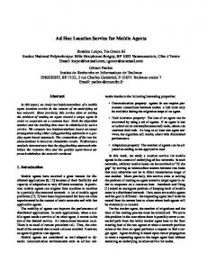
Figure 1: A Smart Printing Service examples of the latter include PDAs and laptops. The capabilities of each device can be summarized in their attributes. Attributes can be static (which do not change with time) or dynamic (which change with time). For example, a network digital camera can have a static attribute “resolution” which can take values like 320x240, 640x480 etc. Examples of dynamic attributes include location (absolute or relative, depending on the availability of GPS), power levels, available computational power (or load), and available communication bandwidth. A service is a functionality provided by a single device or by a federation of cooperating devices. When simple services offered by single devices are composed, a complex service can be formed. We will describe this process in greater detail in Sec. 3. Multiple devices can exist in a MANET offering the same service. A node is a logical or abstract representation of a device or a collection of devices characterized by a minimal set of attributes that can offer a particular service. A node is simple when it represents a single physical device that offers a certain service. It is complex when it represents multiple simple nodes collaborating to offer a particular service. In this paper, we propose a framework for the formation of complex nodes from simple ones. We refer to the principal attribute of a node or a device as its class or category or type. Examples of classes include printer, speaker, joystick etc. Complex nodes are explained in more detail in Sec. 2.3. An edge is a necessary association between two nodes with attributes that must be satisfied for the completion of a task. Examples of edge attributes include causal ordering, weight, required data rate between nodes, allowable bit error rate, and physical proximity.
2.2
Tasks and Task Graphs
We have proposed elsewhere [2] the use of logical resource dependency graphs (we call them task graphs (TG)) for modeling a distributed application on MANETs with specialized devices. According to that definition, a task can be described as work executed by a node with a certain expected outcome. Work done by a component of a complex node is referred to as a sub-task of the bigger task. An atomic task is an indivisible unit of work which is executed by a simple node. Atomicity is related to the core capability of a device, as described by its attributes, and is partially constrained by subjective design choices.
A task graph is a graph T G = (VT , ET ) where VT is the set of nodes that need to participate in the corresponding task, and ET is the set of edges denoting data flow between participating nodes. Although the notion of hierarchical composability is briefly mentioned in [2], we completely concentrate on flat task graphs in that work. In this paper, we argue that hierarchical graphs can naturally model dynamic service composition, and propose a framework for achieving the same. We use the existing framework of flat task graphs as developed in [2]. An example may bring further clarity to the abstractions developed so far. Consider a scenario in which there is a postscript (PS) printer connected to a small computer (print server) running filtering software that can convert PDF files to printable PS format. The printer and the computer are each devices that offer particular services. The printer is a specialized device offering the service of converting PS files into printed pages, while the computer is a multipurpose device which offers a service of converting PDF files into PS format among many other services. The example has been illustrated in Fig. 1. The printer is a physical device representation of a simple node with certain attributes (such as print resolution, ink color) that offer the service of converting PS files into printed pages. Analogously, the print server computer plus its filtering software can be viewed as a representation of a PDF → PS converter node. By taking these two nodes together we can form a complex node that offers a “PDF printing service”. A task we have in mind is the printing of one PDF document. In this specific case, based on subjective criteria, we define an atomic task to be the printing of one page of the document1 . The entire document can be then printed on a set of available printers as shown in Fig. 1. These abstractions and terms are created to allow us to separate the desired outcome (the printed pages of a PDF file) from the elements that enabled such outcome (computer + filtering software and PS printer) and the process involved in obtaining the desired outcome (which is the Task-Graph discussed later). We separate these because in a MANET environment, it is highly likely that even if one such enabling physical device is absent, the desired outcome can still be obtained by accessing other devices of similar (if not equal) attributes. If such separation did not exist, we could be trapped into thinking that what we needed is a specific device, instead of devices of certain attributes. Granted that this example is simple (even trivial), we believe that research that enables such capability in today’s MANETs for arbitrary device types and quantities is essential for tapping into the networked environment’s full potential. Note that in this scenario we formed a new service (PDF printing) by combining two existing ones. This is the basic idea behind composition of two services to yield a third one. We illustrate the idea further by an example in Fig. 2. Let us consider a ubiquitous computing application of image/video capture, storage and printing. A user wants to locate a digital camera, get his/her image captured, preview it and then store it (perhaps temporarily) on available storage devices in his/her surroundings, since the user’s PDA may not have enough capacity to store the photograph. The user may also want to print a suitable image on a nearby printer. Fig. 2 depicts two task graphs for 1
We did not come up with any objectively quantifiable argument as to why the atomic task should not be the printing of a dot in the paper. Subjectively, we believe atomic operations at that level are too cumbersome to manage at such high-level abstraction.
FAULT TOLERANT PEER−TO−PEER STORAGE SERVICE y> < Ke
USER
REQ
y < Ke
parity node
root
CAMERA
preview
4 storage nodes
store pri nt
USER AFTER COMPOSITION
REQ Camera
store
p2p storage service
preview REQ
print−server proximity
PHOTO CAPTURE & STORAGE SERVICE
>
pri nt
printing service
PRINTING SERVICE printer
PHOTO CAPTURE & PRINTING SERVICE
Figure 2: An Example of Service Composition performing the same task, at different levels of abstraction and service composition. In Fig. 2(a), the user requests a camera service, gets his/her picture taken by a nearby camera, previews the picture, and then instructs the camera to store the picture from its buffer into a fault tolerant peer-to-peer (P2P) storage system in the surroundings2 . After the camera discovers a P2P storage service, it stores the image, and the latter returns a key to the user for future access of the image. The printing also proceeds in a similar fashion. However, in Fig. 2(b), the user just requests an instance of a “Photo Capture & Storage” service which is a service “composed” of 2 simpler services, namely, Camera and P2P Storage. In this case, a camera device has already chosen a nearby P2P storage system in the network. Hence, when the user sends a store instruction, the image is stored on the already selected storage nodes with no discovery latency. Note that the fault tolerant P2P storage service is a complex service since it is composed of simpler storage services, hence the composition hierarchy is two levels deep. Each service is represented logically by a “node” in the task graph. Also, a task graph corresponding to a complex service such as “P2P storage” is represented by a node in the hierarchical task graph corresponding to the higher level service. Dynamic Instantiation of Nodes In MANET environments where some devices can be mobile, a user should not depend on a particular device for a desired service; instead, he/she should attempt to access similar services provided by several nodes in the network. Thus, before the execution of a task, specific instances of physical devices are selected, in other words, instantiated, for every logical node in a given TG. More specifically, each type of a node in TG should be “mapped” to one suitable instance of a device or a service for taking part in task execution. The type and attributes of the chosen devices should match those of the nodes in the TG. They are then made to communicate with one another according to the specifications of the TG. Since a participating device may become unavailable due to mobility or failures, a new substitute device with similar capabilities is instantiated dynamically to continue the task, if possible. In Sec. 3.3 we propose mechanisms for recovering from such events during service composition. 2
A fault tolerant P2P storage service is collaboratively provided by a number of devices with available storage space. The fault tolerance is achieved by replication or coding as indicated in the figure.
DEPTH = 0 ROOT 1
2.2
1.1.2
2 DEPTH = 1
1.1.1 1.2 1.1 1.1
1.2
1
DEPTH = 2
2.1
2.1
2.2
2 DEPTH = 3 1.1.1
1.1.2
Figure 3: A Hierarchical Task Graph and Layered Graphs
2.3
Hierarchical Task Graphs
A hierarchical graph contains nodes that are simple or complex. Simple nodes are the leaves of the containment hierarchy (this is intuitively clear but is defined formally in the next paragraph) and are characterized by their type and attributes. A complex node is at an intermediate level of the containment hierarchy and contains another hierarchical graph of smaller size. The containment hierarchy, CH of a hierarchical task graph is a tree structure as depicted in Fig. 3. The containment hierarchy is given by a tree since there are no overlaps between complex nodes at any levels in the hierarchy. In the figure, the nodes have been uniquely numbered or labeled according to their depths in CH3 . For example, in the figure, nodes 1, 2, and 1.1 are complex nodes, whereas 1.1.1, 1.1.2, 1.2, 2.1, and 2.2 are simple nodes. Formally, a hierarchical task graph GH can be defined by a tuple (V, E, CH), where V = Vs ∪ Vc is the set of nodes, and E = Es ∪ Ec is the set of edges between certain pairs of nodes. Vs is the set of simple nodes which are leaf nodes of CH, and Vc is the set of complex nodes which are the intermediate nodes. Es is the set of simple edges between simple nodes, and Ec is the set of complex edges between complex nodes as well as between simple and complex nodes. The definition of a hierarchical task graph that we have given here is general thus far. In Sec. 3.2, we establish a few rules in our instantiation framework that govern the derivation of complex edges from simple edges.
3
Service Composition using Hierarchical Graphs
In the previous section, we described the basic building blocks for service composition. In this section, we describe how the service composition problem can be modeled satisfactorily with hierarchical task graphs. We use the notation developed in Sec. 2.3. 3
The “depth” of the top node in CH is assumed to be 0 and it increases as the tree is traversed downward.
3.1
Structure of a Complex Node
As we have mentioned before, a complex node in a hierarchical TG is an abstract representation of a smaller task graph corresponding to a complex service which can be requested by another device or a service. Consider a complex node Ci ∈ Vc at depth = i in CH. Let (1) (2) |V (C )| V (Ci ) = {Ci+1 , Ci+1 , . . . , Ci+1 i } be the set of nodes at depth = i+1 which are Ci ’s children in CH. Then V (Ci ) is the vertex set for the task graph corresponding to the complex node Ci . Controller Nodes In every instance S˜ of a service S, one physical device out of all participating devices acts as a controller of S for advertising the service and responding to queries for S by other devices. In case of a simple service, the controller is obviously the device providing the service itself. However, in case of a complex service, the controller has to be selected or elected from among all the participating devices. The controller also has a responsibility of carrying out discovery and instantiation of other services that S needs. The specific functions of the controller will become clearer in Sec. 3.2 where we describe the instantiation algorithm in detail. We denote the controller of S by S. Interface Nodes Now, there may exist nodes in V (Ci ) which interact with services outside Ci . We refer to such nodes as “interface nodes” at that particular depth. In Fig. 3, nodes 2.1 and 1.1.2 act as the interface nodes for services depicted by nodes 2 and 1. If IF (Ci ) denotes the set of interface nodes in Ci , then 1 ≤ |IF (Ci )| ≤ |V (Ci )|. Interface nodes are needed during instantiation for continuing the discovery of services which are located downstream from the current node in the task graph at a particular depth in the hierarchy. They also serve as points of data exchange between services. The Type of a Complex Node We favor strong typing of services and hence complex nodes. In other words, in our system every service belongs to a particular type; while requesting a service, a device refers to it by its unique type. There are some atomic “types” in any network of devices and some composed types which are constructed from the atomic types. A close analogy is that of the basic data types in a higher level programming language and the advanced data types that can be constructed from the former.
3.2
Instantiation of Hierarchical Task Graphs
In this subsection, we propose an algorithm for instantiation of hierarchical task graphs in order to achieve service composition. First, we state the assumptions that are needed to make the system work: • We assume the presence of a reactive MANET routing protocol such as AODV [12], DSR [11] etc. and a reliable transport protocol such as TCP. Our protocol will be implemented above the routing/transport layer, and will obey the layering principles. • If S is a service type, we denote by S the instantiated device that advertises S and responds to queries for S from other devices. If S is a simple service, then S is the
device offering that service. On the other hand, if S is a complex service, S is one of the devices that cooperatively offer that service. Also, a complex service is said to be instantiated if all its children nodes in CH have been instantiated. • When the system is in initial stages, devices only answer queries regarding simple services i.e. their core capabilities. However, simple task graphs can be uploaded to these devices either by a user requesting services or during their initialization. For example, a device hosting a print server (P S) may possess a task graph during bootup that will instruct it to discover a printer device (P RT ). In case the task graph is not available during boot up, it may be supplied by the user making the request for a printing service (P). There is an issue to be noted here: if P S has a task graph at boot-up, then it will discover a P RT and can answer user queries about P, since P = P S. However, if P S does not have a task graph, then it cannot respond to user queries about P since it is not aware of that type of service. Hence the user (or the administrator) is expected to supply the relevant task graph to P S so that it is aware that it needs to discover an instance of P RT to be able to offer a complete printing service P. The information known to the user has to be up to a certain depth d in the containment hierarchy of TG such that all services needed at or below d must either already exist in the network or be capable of being formed independently in the network by their component devices. These associations can be cached at the devices so that in future time instants, users can query for P and be served. We believe that a community of users can continually build up a set of services from their simpler components and the logical task graphs which represent the complex services can be shared among the users. This will result in more casual users using services that have been logically composed earlier, at the same time it allows more innovative users to create complex services and then share them with others. The instantiation of a service in most cases will however be done at runtime. In this paper, we assume that a user possesses the task graph along with the containment hierarchy CH so that it does not have to depend upon the existence of any simpler services. However, if any instance of a required simpler service exists in the network, our protocol will attempt to make use of it. Derivation of Complex Edges from Simple Edges Let T Gf lat = (Vs , Es ) be the flat task graph that can be constructed from simple nodes and edges alone. Usually in a flat task graph, the user node is assumed to be the root node. All other nodes are downstream from the user node. The instantiation of nodes in a flat task graph proceeds along the branches of a breadth first search spanning tree4 (BFST) rooted at the user node [2]. If the TG itself is a tree, then there are no non-tree edges in BFST. BFST has no relation with the containment hierarchy CH which is also a tree. We extend this notion of a BFS tree structure rooted at the user node at every depth in a hierarchical TG, and that results in the establishment of the following rules which helps during the instantiation process (this will be more apparent later in Sec. 3.2.1 when we describe the instantiation algorithms): The rationale behind these rules is that an upstream service (or node) gets instantiated entirely before a downstream service. Hence for every simple edge between two nodes, 4
In a BFS spanning tree, vertices which are equidistant from the root are at the same level
Algorithm 1 Rules for Derivation of Complex Edges from Simple Edges Given: e = (ni , nj ) ∈ Es and depth(ni ) ≤ depth(nj ) in CH. if (ni is at a higher level in BFST than nj ) then 1. p ∈ V is the parent node of ni at the lowest depth in the common subtree in CH to which both ni and nj belong, such that p is not the root of the common subtree. p can be ni too. 2. else 1.
∀nc : nc = nj or is a parent of nj and depth(nc ) ≥ depth(p), (p, nc ) ∈ Ec . p ∈ V is the parent node of nj at the lowest depth in the common subtree in CH to which both ni and nj belong, such that p is not the root of the common subtree.
2. ∀nc : nc = ni or is a parent of ni and depth(nc ) ≥ depth(p), (p, nc ) ∈ Ec . end if complex edges exist between the corresponding complex upstream node and simple as well as complex downstream nodes, assuming all these nodes are in one common subtree in CH. These edges are necessitated by aspects of the discovery/instantiation process of downstream nodes by upstream nodes as exemplified by an example later in this section. In Fig. 3, where 2 is a complex root node in the BFST, a simple edge between simple nodes 1.1.2 and 1.2 contributes to a complex edge between complex nodes 1.1 and 1.2. Similarly, the simple edge (2.1, 1.1.2) corresponds to the complex edges: (2.1, 1.1), (2, 1.1), (2, 1.1.2), and (2, 1). We now explain the principal idea behind our instantiation algorithm by means of a simple example for ease of explanation. Detailed steps are explained later in Sec. 3.2.1. Consider the task graph shown in Fig. 3. Suppose 2 has been already instantiated, i.e., 2.1 and 2.2 are known. Let 2 = 2.2. Now, 2 wants to discover an instance of a service of type 1 and broadcasts a query packet with the relevant information. Now there are two possibilities: (1) an instance of service 1 exists, and (2) there is no reachable instance of service 1. In case (1), the controller device of 1 (i.e. 1) receives the query and responds to 2 which is 2.2 in this example. In the response packet which is unicast using underlying MANET routing, 1 sends information about interface node instances (1.1.2 in this case) between nodes 1 and 2, so that actual physical connections can be made between them. When 2.2 receives the ACK message with interface node information, it informs 2.1 to connect to 1.1.2. Device 2.1 also updates its task graph with the new instances of devices participating in service 1. In case (2), no device will answer the query for service 1. It can mean that no instance of service 1 has been composed yet, or that those instances are unreachable from instances of service 2. Hence, service 1 needs to be instantiated on demand. Now, 2.2 will query for individual devices or simpler services, such as 1.1, that constitute service 1. It is possible that 1.1 exists without 1 existing. In that case, 1.1 would want to discover 1.2 in order to have the instance ˜1. But, if 1.1 does not exist, 2 will query for service 1.1.2. An instance 1.1.2 that replies to the query will be instantiated, and then it will continue the search process further. After all requested services have been instantiated, the application can start data transmission. After data transmission is over, the associations between participating nodes can be cached for future use so that a request for a complex service can be fulfilled immediately.
3.2.1
Distributed Algorithms for Instantiation of Hierarchical Task Graphs
Now we describe the steps of the distributed algorithms for achieving service instantiation and composition. All devices execute the same copy of the distributed algorithm except the core user device which acts as a coordinator for state synchronization. The user wants to execute an application and is assumed to possess a relevant task graph for it. We have illustrated earlier in this section examples of situations where higher level knowledge of the services and the interactions between them is not enough. Hence, even if a user may not need deeper layer information about the hierarchical services, his/her PDA should contain the entire task graph to be prepared for the worst case. After a few instances of a complex service have been bootstrapped, later users only need higher level information to discover those relevant services. We discuss this in further detail in Sec. 4. The essentials of the user state machine during the instantiation phase are shown by a distributed algorithm (Algorithm 2). The algorithm that is implemented by the protocol state machine on all other devices in a MANET is given by Algorithm 4. We explain the details of these algorithms in this subsection. The algorithms have been presented as pseudocode with descriptive names for variables and routines. All routines have not been explained to the utmost detail in this paper but the general idea is easy to grasp. Both algorithms are distributed and are driven by events such as arrival of packets of certain types or by expiry of certain timers. The steps within each single execution of the for loops are assumed to be atomic in the sense that if a packet arrives during the execution of some of those “if–then–else” statements, it will be queued and processed only after the control returns to the WaitForPacket() call. Querying for Services The instantiation process begins at the user (coordinator) device (U) which contains a description of the hierarchical task graph corresponding to the application that is desired to be executed5 . In the beginning, a task graph TG is extracted from GH at depth d = 1, i.e., only the top level service descriptions are known to the algorithm at this stage. Then the nodes in TG which are neighbors of U are queried (Algo-2::6–9). The broadcast query packet contains a query string (Qstr ) which constitutes of the type of the requested service. Generally, the entire service hierarchy is included in the query string starting from the querier’s own depth. The coordinator node starts a timer after broadcasting the queries. If the timer expires before it gets any response, it handles the situation by querying a less complex service, an instance of which may be available in the network (HandleBroadcastTimeouts() at Algo-2::40). Detailed steps can be found in Algorithm 3. The complex edges that were introduced in GH by Algorithm 1 are useful at this stage since the coordinator knows exactly what service to query for if it does not hear a response from an instance of a higher level service. Although we don’t mention it explicitly, we assume that all steps to control a broadcast storms will be taken. Some of these salient steps include the use of TTL scoping, maintenance of broadcast sequence numbers so as not to rebroadcast an old packet etc. We do not discuss these in detail in this paper. 5
The task graph can be represented using an extension of the XML specification language called GraphXML [7].
State Management in Devices and Response to Broadcast Queries Notationally, we assume a generic initial state in the non-coordinator algorithm given by S[i], i = 1 . . . m (Algo-4::1) but at the very beginning when no instances of complex services exist in the network, each device is a member of only one service instance, the one that it provides alone, atomically (m = 0). With progression of time, devices start taking part in multiple services at various levels of complexity. This is not to be confused with the depth of the corresponding node in the absolute CH. A “higher-level service” always refers to a service at a lower depth in CH. At any level of complexity i, a device’s state is given by state[i] which has two disjoint components: whether it has been instantiated at that level (denoted by one of the 3 states, UNINST, WAIT FOR ACK, or INST) or if it is a controller of that service or just a plain member (denoted by SRV MEMBER, or SRV CONTROLLER). When a devices receives a service query packet (Algo-4::4-8) with a query string Sk1 :: Sk2 :: . . . :: Skn , where Sk1 is the simplest service and Skn is the most complex service, it tries to find a match with the most complex service that it can offer at that instant of time6 . If the device is a controller of the service at that level and it is uninstantiated, then it accepts the request for service and sends a response to the sender as a possible candidate. It also changes its state from “uninstantiated” to “waiting for acknowledgment,” and starts a timer (not shown). If the timer expires before receiving an ACK from the sender, the state is changed back to uninstantiated.
6
MaxMatch tries to find the most complex entry in the query string that matches S[m]. It returns −1 if no match is found.
Algorithm 2 Coordinator Device Instantiation Algorithm 1: Given: Hierarchical Task Graph, GH = (V, E, CH). 2: T G(VT , ET ) ← ExtractTG(GH , d ← 1); /* extract task graph at depth d = 1 from GH */ 3: Vngb ← {v ∈ VT | v is user node U’s neighbor in T G}; /* neighboring service nodes in T G */ 4: U ninstSrv ← VT ; U ninstSrvngb ← Vngb ; /* uninstantiated services:(all+neighboring) */ 5: InstSrv ← φ; InstSrvngb ← φ; /* instantiated services:(all+neighboring) */ 6: for (∀v ∈ U ninstSrvngb ) do 7: v.acked ← FALSE; /* initialize acked variable */ 8: v.Qstr ← v.service type; /* initialize Query string */ 9: BroadcastQuery(v.Qstr ); /* begin search for required service instances */ 10: end for 11: 12: for (; ;) do 13: WaitForPacket(pkt); /* can forward broadcast packets too in this state 14: 15: 16: 17: 18: 19: 20: 21: 22: 23: 24: 25: 26: 27: 28: 29: 30: 31: 32: 33: 34: 35:
*/ if (pkt.type = CANDIDATE RESPONSE) then /* response to broadcast query */ if ((∃w ∈ U ninstSrvngb | w.service type = pkt.service type; ) ∧ (w.acked = FALSE)) then SendAck(pkt.srcaddr, GH ); /* send ACK along with the task graph */ w.acked ← TRUE; end if else if (pkt.type = CONFIRMATION ∧ (w ← pkt.service type)) then /* the controller of a service confirmed the receipt of an ACK pkt */ g ← Extract Subgraph(pkt); w.controller = pkt.srcaddr; Instantiate(GH , g); /* instantiate nodes in GH with physical addresses */ U ninstSrv ← U ninstSrv \ {w}; U ninstSrvngb ← U ninstSrvngb \ {w}; InstSrv ← InstSrv ∪ {w}; InstSrvngb ← InstSrvngb ∪ {w}; /* update service vars */ else if (pkt.type = SUBTREE CONF ∧ (∃s ∈ InstSrvngb : s.controller = pkt.srcaddr)) then /* an entire subtree has been confirmed to be instantiated */ g ← Extract Subgraph(pkt); Instantiate(GH , g); /* instantiate nodes in GH with physical addresses */ SubtreeSrv ← {s0 | s0 is in the subtree at depth d = 1 rooted at s}; /* extract subtree nodes */ U ninstSrv ← U ninstSrv \ SubtreeSrv; InstSrv ← InstSrv ∪ SubtreeSrv; /* update global service variables */ if (U ninstSrv = φ) then Send Interface Node information regarding non-tree edges to controller nodes of services.
Algorithm 3 HandleBroadcastTimeouts() 1: S[m] = {i0 , i0 .i1 , i0 .i1 .i2 , · · · , i0 .i1 . . . . .im } /* initially, max.level m = 0 ⇒ S = {Satom } */ 2: ∀u ∈ U ninstSrvngb such that u.active = TRUE : /* check for all active, uninst. services */ 3: if (TimeOut(u.service type) = TRUE) then 4: /* if no instance found for u in a specified timeout period */ 5: V 0 ← {v 0 ∈ V | v 0 is u’s child in CH and (S[m], v 0 ) ∈ E}; /* find simpler services in GH */ 6: U ninstSrvngb ← U ninstSrvngb ∪ V 0 ; u.active ← FALSE; /* update service variables */ /* 7: ∀x ∈ V 0 : { x.Qstr ← u.Qstr :: x.service type; BroadcastQuery(x.Qstr ); } issue queries */ 8: end if
Algorithm 4 Non-Coordinator Device Instantiation Algorithm 1: Given: Own Service Types and Instantiation states at different levels in the “relative” hierarchy: S[m] = {i0 , i0 .i1 , i0 .i1 .i2 , · · · , i0 .i1 . . . . .im } /* initially, max.level m = 0 ⇒ S = {Satom } */ ∀i : state[i] ∈ {UNINST, WAIT FOR ACK, INST} × {SRV MEMBER, SRV CONTROLLER} 2: for (; ;) do 3: WaitForPacket(pkt); /* can forward broadcast packets too in this state */ 4: if ((pkt.type = SEARCH QUERY) ∧ (MaxMatch(pkt.Qstr , S[m]) 6= −1)) then 5: if (state[m] & (SRV CONTROLLER | UNINST)) then 6: SendCandidateResponse(pkt.srcaddr, S[m]); /* send CANDIDATE RESPONSE upstream */ 7: state[m] ← state[m] & ˜UNINST | WAIT FOR ACK; /* change state to WAIT FOR ACK */ 8: end if 9: else if ((pkt.type = ACK) ∧ (∃i : S[i] = pkt.service type) ∧ (state[i] & WAIT FOR ACK)) then 10: GH ← Extract TaskGraph(pkt); /* extract rest of the task graph */ 11: state[i . . . m] ← state[i . . . m] & ˜WAIT FOR ACK | INST; /* update states to INST */ 12: Cout ← ExtractInterfaceNodeInfo(GH , S[m]); /* downstream interface nodes */ 13: SendConfirm(pkt.srcaddr, S[m]); /* send CONFIRMATION of service instantiation */ 14: if ((c ← FindChildren(GH , S[m])) 6= φ) then 15: ∀x ∈ Cout : InstructNodeToContinueSearch(x, c(x), GH ); /* send CONTINUE SEARCH */ 16: else 17: SendSubtreeConfirm(pkt.srcaddr, S[m]); /* send SUBTREE CONF to parent */ 18: end if 19: else if (pkt.type = CANDIDATE RESPONSE) then 20: if ((∃w ∈ U ninstSrvngb : w.service type = pkt.service type) ∧ (w.acked = FALSE)) then 21: SendAck(pkt.srcaddr, GH ); w.acked ← TRUE; /* send ACK to the candidate device */ 22: end if 23: else if (pkt.type = CONFIRMATION ∧ (w ← pkt.service type)) then 24: if (S[m].controller 6= M yAddr) then InformController(pkt); continue; end if 25: g ← Extract Subgraph(pkt); w.controller = pkt.srcaddr; Instantiate(GH , g); 26: U ninstSrv ← U ninstSrv \ {w}; U ninstSrvngb ← U ninstSrvngb \ {w}; 27: InstSrv ← InstSrv ∪ {w}; InstSrvngb ← InstSrvngb ∪ {w}; /* update service vars */ 28: else if (pkt.type = SUBTREE CONF ∧ (∃s ∈ InstSrvngb : s.controller = pkt.srcaddr)) then 29: if (S[m].controller 6= M yAddr) then InformController(pkt); continue; end
Instantiation of Services and Confirmation A coordinator can receive responses from several candidate service instances out of which only one is sent an ACK (Algo-2::13-18). However, the instantiation of that service is completed only when the controller of that service replies to the ACK packet with a CONFIRMATION packet (Algo-4::9-18). These steps require some more explanation. The coordinator sends the task graph GH along with the ACK packet so that the chosen candidate service instance can continue the process of discovery of its children nodes and their instantiation. Hence, at any stage, the responsibility of instantiation of hitherto uninstantiated services is distributed among the controllers of the nodes that have already been instantiated, more precisely among their parent nodes in the embedded tree in GH . After a candidate controller device receives an ACK, it changes its state from “waiting for ACK” to “instantiated.” Imagine a situation when a coordinator had queried for a complex service CS, then timed out because there were no instances of CS, and then it queried for a simpler constituent of CS, namely SS. Suppose, a candidate device D had responded to the SS query but by the time it got an ACK from the coordinator, it had already formed an instance of CS independently and that was available for use. When the ACK for SS (S[i] in line Algo-4::9) arrives at D, it replies with a confirmation message for CS (S[m], m ≥ i in line Algo-4::13) since the requester had originally wanted to discover an instance of CS only. Simultaneously, D extracts the interface node information from the task graph as well as information about who its children are in the embedded BFS tree rooted at node S[m]. The interface node information is important since those are the devices that will have interfaces with
the controllers of downstream services, and hence it is logical that they continue the discovery. When a CONFIRMATION packet arrives at the coordinator device, the latter concludes that the sender of the packet S is acting as a controller on behalf of the devices that are offering a desired service. The arrival of this packet also means that S has taken up the responsibility of discovering downstream services. The coordinator meanwhile instantiates S in it own copy of the task graph. Subtree Confirmations Data transmission can begin only when required services have been instantiated. Since the instantiation process is distributed and local, the coordinator needs to be informed when the instantiation is over. We achieve this by means of subtree confirmation packets. When all downstream services rooted at a particular service node in the task graph have been instantiated, it propagates a SUBTREE CONF packet upstream all the way up to the coordinator. The coordinator extracts the task graph from the packet and instantiates the downstream nodes indicated in the task graph in its own copy. If all services in its list have been instantiated then the flow of application data can begin (Algo-2::33-37). Also, exchange of periodic heartbeat messages begins between the coordinator and the controllers of services in GH at the top level. This is for monitoring failures and disconnections between service instances. We explain this in further detail in Sec. 3.3. Interestingly, this process occurs at all levels of the hierarchy inside every complex node for completion the instantiation inside them. The controllers of each service node serves as the root node akin to the user node for the entire application. The use of subtree
confirmation results in much less overhead this interface device by Sif . S¯ instructs Sif to than individual confirmation sent to the con- search for Z. When Sif broadcasts a query, trollers. Z¯ responds and then upon getting an ACK, sends a confirmation to Sif which relays it to Composition and Instantiation of S¯ (Algo-4::24). The broadcast timeout rules Complex Downstream Nodes As we apply to Sif as they apply to the Coordinator have mentioned earlier in this section, the device. If a controller C of a service at level m Coordinator device is deemed responsible for instantiating the devices that are finds that it is at the BFS-root of a complex its neighbors at the top level of GH . node in GH at depth d in CH and that it Instantiation of downstream services needs has received SUBTREE CONF messages from to be performed by devices which interface all controllers Ci at level m, it concludes with those services. Addresses of such that a new service S[m + 1] can be composed devices within an instantiated service S[m] and instantiated at depth d − 1 from all 8 can be extracted by the service controller these existing service instances . This has from the task graph (Algo-4::12), and been illustrated in Algo-4::34-43. Function those devices can be instructed by the ConstructSrvName() constructs a name controller to continue the search downstream for the complex service using a standardized (Algo-4::15). When an interface device convention known to all devices in the receives a CONTINUE SEARCH packet, it network. After forming this new service executes steps (Algo-4::44-49) similar to the instance, C assumes the role of the controller of this service too. It also informs all ones executed by the coordinator device. controllers C (available from the variable i Lines 19-43 in Algorithm 4 correspond to the steps taken for instantiating a down- InstSrv) that they should change their state stream node. Although these steps and the to SRV MEMBER with respect to S[m + 1]. corresponding steps of the coordinator algo- Also, since the instantiation occurred only rithm that we have described before are quite along the edges of the BFS tree of the similar in intent, there are some subtle dif- appropriate subgraph of GH , if the latter ferences between them. We illustrate those has any non-tree edges, the affected interface differences with an example. Suppose that nodes should be informed about each other’s a service S with a corresponding task graph addresses so that they can communicate. T GS (this may itself be hierarchical) has been Now, if C had been queried and all the instantiated. We represent the collection de- above steps happened on-demand, then vices that have instantiated S by S˜ and the after S[m + 1] is formed, C responds to the ¯ Suppose S can form a upstream interface node which had initiated controller of S by S. more complex service if it uses another service broadcast for S[m + 1]. Otherwise, C does Z which itself is a complex service. If Z has nothing and waits to be used. From the above description of the albeen instantiated earlier independently, Z˜ ex¯ Now, a from higher level gorithms, we can see that although their deists, and so does Z. task graph description GH (involving smaller scription is slightly cumbersome due to the nodes T GS and T GZ ), S¯ knows its outgoing specific details, the basic idea behind the hiinterface between S˜ and Z˜ 7 . Let us denote 8 Note that in this context depth is an absolute This information is extracted from GH by Ex- value in CH which increases as complexity in services reduces; on the contrary, level is a relative value which tractInterfaceNodeInfo() at Algo-4::12. grows as complexity of a composed service increases. 7
erarchical composition and instantiation of present steps for performing recovery from services is simple and very useful. such situations.
3.3
Recovering from Discon- 3.3.1 Detection of Disruptions in Service nections and Disruptions The first essential step for recovery from a due to Mobility
Algorithms 2 and 4 describe the process of instantiation of a hierarchical task graph on a set of nodes in a MANET. In this section, we present in detail how these algorithms react to the mobility of devices after the required services have been instantiated. In a MANET, if relative mobility of devices is very low and if the existing network topology does not change due to mobility, the application will not be disrupted at all. However, on most occasions, existing routes can fail due to mobility of devices owing to the change in network topology, and that can cause a temporary disruption in the application. The underlying MANET routing protocol then attempts to rediscover an alternate route to the same destination. If the rediscovery happens quickly then the application does not perceive a glitch and continues to run smoothly. However, if the time taken to rediscover an alternate route is large or if a network partition occurs because of device movement, the application is disrupted for a longer timescale. Therefore, in mobile networks, it is not sufficient to discover specific instances of services and appoint them permanently to execute the application – accessibility of those service instances needs to be continually monitored in order to detect disruptions, and replacement services must be discovered, if possible, for resuming the application. Since this can be a regularly occurring phenomenon in real MANETs, it is extremely important to augment the previously mentioned algorithms such that they can recover from such disruptions as rapidly as possible. In this section, we
disruption of service is its detection. Mobility of devices may cause network partitions or disconnections, and instantiated devices executing a service may no longer be able to communicate if all paths between them are broken. We propose a lightweight, soft-state exchange protocol for detecting disconnections in an instantiated task graph. The protocol requires the controller device of a service to send periodic I-AM-ALIVE or HELLO messages to all other controllers devices that are cooperatively offering the service at the same depth in the containment hierarchy. These controllers reply with a HELLO-ACK message within a pre-determined period of time T . This is illustrated in Fig. 4. A “hierarchically clustered” detection scheme is favorable in this context instead of a purely distributed one since most of the state of a particular service at a given depth in the containment hierarchy lies with the controller device for that service. Also, by limiting the HELLO packet exchange to controllers of the same containment hierarchy that are cooperatively offering one service we actually obtain a scoped detection scheme, which is more scalable than a detection scheme applied to a flat graph. Thus, in Fig. 4, device 1 exchanges HELLO and HELLO-ACK packets only with devices 2.1 and 3.1, since 1, 2.1 and 3.1 are controllers of service instances S˜1 , S˜2 and S˜3 , respectively, and they are represented by nodes that belong to the same depth in the containment hierarchy of the task graph. Note that 2.1, as the controller device of S˜2 , also needs to exchange HELLO and HELLO-ACK packets with the other controllers, namely, 2.2 and
S1
Controller Device
1
DEPTH = 0
Service
3.1
S2 2
2.1
DEPTH = 1
3 1
3.3
3.4 3.2 2.2
2.3
2.2
3.4.1
S 3.4
2.1
2.3
3.1
3.2
DEPTH = 3
3.4.3 3.4.2
3.4.3
DEPTH = 2
3.3
3.4.1
3.4.2
HELLO/HELLO−ACK PKT EXCHANGE Containment Hierarchy Depth
3 2
Containment Hierarchy
S3
1
Figure 4: Disruption Detection in a Hierarchical Service Instance 2.3 that cooperatively offer S˜2 together. The HELLO-ACK packet is sent by the controller of a cooperating complex service only when all the constituents of the service have replied with their HELLO-ACK packets within the proper time-out period. Thus, in Fig. 4, 2.1, as the controller of S˜2 , would only send a HELLO-ACK back to 1 when it has received HELLO-ACK from 2.2 and 2.3 within the proper time-out period. This clustered approach reduces the number of devices that must be tracked simultaneously by any single device but obviously increases the time needed to obtain all the HELLO-ACK packets from devices that are further down in the containment hierarchy. In this scenario, if we keep a single value for the time-out period T , then we run the risk that, upon meeting a service represented by a task graph with enough containment hierarchy levels, the lower level nodes (e.g., a device that act as node 3.4.2 in Fig. 4) will not even have been queried for when the higher level node controllers (e.g. 1 in the same figure) suffer time-out. To deal with this problem, we propose a time-out value that is proportional to the number of levels left to reach the lowest containment hi-
erarchy level of an instantiated task graph. Therefore, if d is the current depth level, N is the lowest containment hierarchy level and T is the time-out value at the lowest containment hierarchy level, then the time-out T (d) is (N − d)T . This approach results in a more frequent packet exchange rate between devices offering simple services than the packet exchange rate between controllers of complex services. If a device requesting a particular service knows the maximum containment hierarchy level (e.g., has a hierarchical task graph representation of the service composed by simple nodes) then a proper initial time-out value can be determined when attempting instantiation. However, if the maximum containment hierarchy level is unknown, design criteria or user input should determine how long to wait before considering that there are no instances available of the service. 3.3.2
The Recovery Process
The recovery process is always initiated by a controller. The controller device of a complex service that does not receive a
HELLO-ACK from the controller of one of its constituent simpler services deems that to be unreachable. Since the constituents of a complex service are services themselves, the controller device of the complex service will attempt to find another instance of the unreachable constituent service. In Fig. 4, if device 3.4.2 does not send HELLO-ACK to 3.4.1 within the proper time-out period, 3.4.1 will not send HELLO-ACK back to 3.1, which in its turn will not send back HELLO-ACK to 1. Because the time-out period involving 3.4.1 and 3.4.2 is shorter, an attempt to find a new replacement instance of 3.4.2 will take place before the time-out period is reached for 3.4.1 and 3.1. In case the replacement is successfully found, 3.1 will receive a proper HELLO-ACK within the allotted time interval and will not be even aware that a recovery took place9 . This common fate sharing characteristic of the components of a complex service in the detection and recovery processes may arguably not yield the optimal performance in terms of delays. However, allowing a partially instantiated complex service to respond as if it were fully instantiated means that application data should then be allowed to be delivered to that instance, even if the application data was to be specifically delivered to the missing component. This introduces problems of where to store data that were intended to the missing component. Since devices in a MANET are more prone to experience unreachability, the best element to buffer the original application data is still their originator. This, added to the fact that we desire to hide the internal details of a complex service from the device requesting
the service prompt us to treat an instance of a complex service as a whole, and thus the fate sharing characteristic. We should note that this design emphasized data delivery. Of course if a higher value is given to the timely arrival of any available data, then it is simply a matter of changing the HELLO-ACK response policy, i.e., to respond as long as there is at least one component of the complex service available.
4
Issues in Performance Evaluation
In this section, we address issues related to the performance evaluation the protocols proposed in Sec. 3. We are currently implementing the protocols on a MANET testbed of laptops and handhelds that we have setup in our laboratory. In the algorithms presented in Sec. 3, we have implicitly assumed that the service instance which is the first to respond to a broadcast query is instantiated by an upstream controller device. By this mechanism, the speed of instantiation is maximized. This can be generalized by defining the notion of average cost of a service instance. Every logical node corresponding to a service in a hierarchical task graph gets mapped onto a set of physical devices which actually execute the service. One can define a generalized cost function f : S → R+ where S is the set of all possible service instances of S that are currently available in the network. If S is composed of simpler services, S1 , S2 , . . . , Sn , and the costs of their instances are given by f (S˜i ), ∀i : 1 ≤ i ≤ n, then the cost of S˜ is ˜ = Ψ(f (S˜1 ), f (S˜2 ), . . . , f (S˜n )). given by: f (S) The functions f and Ψ can be constructed so as to reflect any performance characteristics related to nodes such as load or bat9 The exception is if the lost service acted as an interface node in the task graph, in which case the tery power, or edge characteristics such as communication delay, diameter of the netnew instance’s address must be notified.
work formed by instantiated devices etc. A slight modification to our current algorithms is sufficient to incorporate this generic cost function. Another performance related issue is messaging overhead the main source of which is the broadcast traffic used in during the discovery phase. This can be controlled by some standard techniques which were very briefly discussed in Sec. 3.2.1. However those are generic techniques for mitigating any kind of broadcast storm. In addition of using those techniques, we can use some caching policies that can be beneficial to the same end. When a device broadcasts a query for a service, several candidate devices can respond to the query, only one of which is finally selected and used. However, if we cache all or some of the addresses that responded to the query, they can be used in the event of a failure of the current candidate at a later time. Specifically, if the service instance currently in use gets disrupted or disconnected, instead of issuing another broadcast query, the controller can communicate with the cached addresses by unicast to determine which one of them is currently suitable for use. If a proactive routing protocol such as OLSR [10] is used instead of a reactive one, dependence upon explicit broadcast at the application level may be greatly reduced by allowing the devices to advertise their capabilities along with their routes. However, owing to the general inefficiency of proactive protocols in terms of control overhead, interesting comparisons can be made between these two approaches with respect to total overhead. One obvious question that can be raised about our scheme is that what happens if all users do not have the entire hierarchical task graph before starting the instantiation process. Our argument is that in a continually used ubiquitous computing environment, already instantiated services
are expected to exist in the network. In such a situation, users with incomplete knowledge of the containment hierarchy can successfully discover and use those services as they do not have to compose them on demand. However, a user who wants to use a service whose instance does not exist in the network has to compose the service from its components and for that it needs deeper knowledge of the containment hierarchy. Another factor that can affect the latency of service discovery is the amount of time for which a complex service is kept instantiated after it has been used. If it destroys itself quickly, then users who arrive into the system slightly later may have to compose it again and thus suffer from large latency. On the other hand if the instance is kept alive for a long period of time, the network can suffer from underutilization due to tying up of the constituent resources of the service. An adaptive scheme can be useful here – more popular services can be kept instantiated for longer periods of time than less popular ones. In Sec. 3.3, we mentioned the use of different timeout values at different depths in the hierarchy. These timeout values can play a really critical role in the performance of the application in terms of its uptime. Hence, the default values of timeout for every level have to be carefully set so that a timeout reflects true disconnection instead of transient behavior. Adaptive timeouts are necessary in order to adapt to changing network conditions which are common features of a MANET. The algorithms described in this paper cater to situations where devices cooperate to execute a single application desired by a single user. In future these algorithms will be augmented to handle multiple instances of tasks and services on the same network. A device such as a computing fabric can be shared by multiple instances of services at the same time, while a camera device cannot.
Characteristics such as fraction of shareable devices, and number of instances of a task in the network can act as interesting input parameters for performance evaluation.
5
Conclusions and Future Work
We introduced the concept of distributed service composition in the context of mobile ad hoc networks. We defined service composition as the process of combining several simpler services to form a meaningful composite service which can be used by a user or other such services in a network. These services can be composed on demand or can self organize dynamically. After a service is composed on demand and used, its components retain their associations for a certain interval of time. If another user requests the service after the first one has finished using it but before it is scheduled to disintegrate, he/she does not have to compose it on demand. This approach can lead to better resource utilization, lower resource and service discovery latency, and can offer users a powerful abstraction of being able to query and use higher level services even if they do not know its individual components. In this paper we presented an approach for modeling service composition using hierarchical task graphs. We proposed distributed algorithms for instantiating hierarchical task graphs and for handling disruptions in services due to mobility of devices. This is only our first step towards investigating the service composition problem and we are currently implementing these algorithms on a MANET testbed as well as in a network simulator for rigorous testing.
References [1] G. Banavar, J. Beck, E. Gluzberg, J. Munson, J. Sussman, and D. Zukowski, “Challenges: An Application Model for Pervasive Computing,” Proc. 6th ACM MobiCom, Boston, MA, August 2000. [2] P. Basu, W. Ke, and T.D.C. Little, “A Novel Approach for Execution of Distributed Tasks on Mobile Ad Hoc Networks,” Proc. IEEE WCNC ’02, Orlando, FL, March 2002. [3] Bluetooth http://www.bluetooth.com
SIG,
[4] B. P. Crow, I. Widjaja, J. G. Kim, P. T. Sakai, “IEEE 802.11 wireless local area networks,” IEEE Communications Magazine, Vol. 35, No. 9, September 1997, pp. 116-126. [5] S. E. Czerwinski, B. Y. Zhao, T. D. Hodes, A. D. Joseph, and R. H. Katz, “An Architecture for a Secure Service Discovery Service,” Proc. ACM Mobicom ’99, Seattle, WA, Aug. 1999. [6] E. Guttman, “Service Location Protocol: Automatic Discovery of IP Network Services”, IEEE Internet Computing, July 1999. [7] Graph XML Specifications. http://www.cwi.nl/InfoVisu/GraphXML/ [8] Hiperlan-2 Global http://www.hiperlan-2.com
Forum.
[9] T. Hodes, R. Katz, E. Servan-Screiber, and L. Rowe, “Composable Ad-Hoc Mobile Services for Universal Interaction,” Proc. 3rd ACM MobiCom, 1997. [10] P. Jacquet, P. Muhlethaler, A. Qayyum, A. Laouiti, L. Viennot, and T. Clausen,
“Optimized Link State Routing Protocol,” Internet-Draft, draft-ietf-manetolsr-04.txt, September 2001. Work in Progress. [11] D. B. Johnson and D. A. Maltz, “Dynamic Source Routing in Ad Hoc Wireless Networks”, in Mobile Computing, edited by Tomasz Imielinski and Hank Korth, chapter 5, pages 153-181, Kluwer Academic Publishers, 1996. [12] C. E. Perkins, E. M. Royer, and S. R. Das, “Ad Hoc On-Demand Distance Vector (AODV) Routing,” InternetDraft, draft-ietf-manet-aodv-08.txt, March 2001. Work in Progress. [13] R. Ramanathan and M. Steenstrup, “Hierarchically-Organized Multihop Mobile Networks for Quality-of-service Support,” ACM/Baltzer Journal on Mobile Networks and Applications, Vol. 3, No. 2, August 1998. [14] The Salutation Consortium. http://www.salutation.org [15] Sun Microsystems, “Jini Technology Core Platform Specification,” http://www.sun.com/jini/specs [16] The Universal Plug-n-Play http://www.upnp.org
Forum.