SCALABLE VECTOR PROCESSORS. FOR EMBEDDED SYSTEMS. Published
by the IEEE Computer Society. 0272-1732/03/$17.00 2003 IEEE ...
SCALABLE VECTOR PROCESSORS FOR EMBEDDED SYSTEMS FOR EMBEDDED APPLICATIONS WITH DATA-LEVEL PARALLELISM, A VECTOR PROCESSOR OFFERS HIGH PERFORMANCE AT LOW POWER CONSUMPTION AND LOW DESIGN COMPLEXITY. UNLIKE SUPERSCALAR AND VLIW DESIGNS, A VECTOR PROCESSOR IS SCALABLE AND CAN OPTIMALLY MATCH SPECIFIC APPLICATION REQUIREMENTS.
Christoforos E. Kozyrakis Stanford University David A. Patterson University of California at Berkeley
36
Designers of embedded processors have typically optimized for low power consumption and low design complexity to minimize cost. Performance was a secondary consideration. Nowadays, many embedded systems (set-top boxes, game consoles, personal digital assistants, and cell phones) commonly perform computation-intensive media tasks such as video processing, speech transcoding, graphics, and high-bandwidth telecommunications. Consequently, modern embedded processors must provide high performance in addition to low cost. They must also be easy to scale and customize to meet the rigorous time-to-market requirements for consumer electronic products. The conventional wisdom for high-performance embedded processors is to use the superscalar or very large instruction word (VLIW) paradigms developed for desktop computing. Both approaches exploit instruction-level parallelism (ILP) in applications in order to execute in parallel a few operations per cycle. Superscalar processors detect ILP dynamically with hardware, which leads to increased power consumption and complexity. VLIW processors rely on the compiler to detect ILP, which
leads to increased code size. Both approaches are difficult to scale because they require either significant hardware redesign (superscalar) or instruction-set redefinition (VLIW). Furthermore, scaling up either of the two exacerbates their initial disadvantages. This article advocates an alternative approach to embedded processors that provides high performance for critical tasks without sacrificing power efficiency or design simplicity. The key observation is that multimedia and telecommunications tasks contain large amounts of data-level parallelism (DLP). Hence, it’s not surprising that we revisit vector architectures, the paradigm developed for high performance with the large-scale DLP available in scientific computations.1 Just as superscalar and VLIW processors for desktop systems adjusted to accommodate embedded designs, we can revise vector architectures for supercomputers to serve in embedded applications. To demonstrate that vector architectures meet the requirements of embedded media processing, we evaluate the Vector IRAM, or VIRAM (pronounced “V-IRAM”), architecture developed at UC Berkeley, using benchmarks from the Embedded Microprocessor
Published by the IEEE Computer Society
0272-1732/03/$17.00 2003 IEEE
Benchmark Consortium (EEMBC). Our evaluation covers all three components of the VIRAM architecture: the instruction set, the vectorizing compiler, and the processor microarchitecture. We show that a compiler can vectorize embedded tasks automatically without compromising code density. We also describe a prototype vector processor that outperforms high-end superscalar and VLIW designs by 1.5× to 100× for media tasks, without compromising power consumption. Finally, we demonstrate that clustering and modular design techniques let a vector processor scale to tens of arithmetic data paths before wide instruction-issue capabilities become necessary.
Vector instruction set for multimedia The VIRAM architecture is a complete load-store vector instruction set defined as a coprocessor extension to the MIPS architecture. VIRAM’s core features resemble those of vector architectures for supercomputing. The vector state includes a vector register file (VRF) with 32 registers that can store integer or floating-point elements, a 16-entry flag register file that contains vectors with single-bit elements, and a few scalar registers for control values and base memory addresses. The number of elements per vector or flag register is implementation dependent. The instruction set contains integer and floating-point arithmetic instructions that operate on vectors stored in the register file, as well as logical functions and operations such as population count that use the flag registers. Vector load and store instructions support the three common access patterns: unit stride, strided, and indexed (scatter/gather). To enable vectorization of multimedia tasks, VIRAM includes several media-specific enhancements. The elements in the vector registers can be 64, 32, or 16 bits wide. Thus, multiple narrow elements can occupy the storage location for one wide element. Similarly, we partitioned each 64-bit data path in the processor implementation so that it can execute multiple narrow-element operations in parallel. Instead of specifying the element and operation width in the instruction opcode, we use a control register typically set once per group of nested loops. Integer instructions support saturated and
fixed-point arithmetic. Specifically, VIRAM includes a flexible multiply-add model that supports arbitrary fixed-point formats without using accumulators or extended-precision registers. Three vector instructions implement element permutations within vector registers. We limit their scope to the vectorization of dot products (reductions) and fast Fourier transforms, which makes them regular and simple to implement. Finally, VIRAM uses the flag registers to support conditional (predicated) execution of element operations for virtually all vector instructions2 and to support speculative vectorization of loops with data-dependent exit points. The VIRAM architecture includes several features that help in developing general-purpose systems—features untypical of traditional vector supercomputers. It provides full support for paged virtual addressing using a separate translation look-aside buffer (TLB) for vector memory accesses. It also provides a mechanism that lets the operating system defer the saving and restoring of vector state during context switches until it knows that the new process uses vector instructions.
Vectorizing compiler The VIRAM compiler can automatically vectorize C, C++, and Fortran 90 programs. It’s based on the PDGCS compilation system for Cray supercomputers such as the C90YMP, the T3E, and the X1. The optimizer has extensive capabilities for automatic vectorization, including outer-loop vectorization and the handling of partially vectorizable language constructs. For many multimedia codes, including all those considered in this article, vectorization is possible without modifications to the original code; special function intrinsics or custom libraries are not necessary for vectorization. However, for certain cases with irregular scatter/gather patterns, the programmer must use a small set of pragmas to help the compiler with data-dependence analysis. The two main challenges in adapting a supercomputing compiler to a multimedia architecture were support for narrow data types and the vectorization of dot products. We modified the compiler to select the vector element and operation width for each group of nested loops in two passes. The compiler also recognizes reductions with common
NOVEMBER–DECEMBER 2003
37
MICRO TOP PICKS
Table 1. Vectorization and code size statistics for the EEMBC benchmarks.
Benchmark Consumer Rgb2cmyk Rgb2yiq Filter JPEG Telecom Autocor Convenc Bital FFT Viterbi Average
Vector operations (percentage)
Average vector length (element width)
VIRAM code size (bytes)
MIPS/ VIRAM code size ratio
VLIW/ VIRAM code size ratio
VLIW-opt/ VIRAM code size ratio
99.6 98.9 99.2 66.0
128 (16b) 64 (32b) 106 (16b) 70 (16b) 13 (32b)
672 528 1,328 65,280
2.7 3.0 1.5 0.9
1.1 1.7 0.7 0.5
3.8 8.2 3.5 1.8
9.1 65.5 2.7 2.6
94.7 97.1 95.7 98.9 92.1 93.8
43 (32b) 128 (16b) 38 (32b) 64 (32b) 18 (16b) 86 (16b) 39 (32b)
1,072 704 1,024 3,312 2,592 NA
1.1 2.3 1.5 1.7 1.5 1.8
0.5 1.1 0.7 4.7 0.5 1.3
0.9 1.6 2.3 0.9 0.7 2.6
1.4 2.9 1.3 1.1 1.0 9.7
arithmetic, logical, and comparison operations, and it uses the permutation instructions to vectorize them. Table 1 shows the results from using the VIRAM compiler with the telecommunications and consumer benchmarks in the EEMBC suite. Three benchmarks (Autocor, Bital, and FFT) use permutation instructions, and three other benchmarks (JPEG, Bital, and Viterbi) require conditional vector execution. The degree of vectorization—the percentage of all operations specified by vector instructions—is greater than 90 percent for nine out of 10 benchmarks; the 10th benchmark’s degree of vectorization is 66 percent. The overall high degree of vectorization suggests that the compiler is effective at discovering the DLP in each benchmark and expressing it with vector instructions. It also indicates that using vector hardware can accelerate a significant portion of the execution time. Table 1 also shows the average vector length for each benchmark. The maximum vector length for this experiment is 64 elements for 32bit operations and 128 elements for 16-bit operations. Very long vectors, typical in scientific computing, significantly simplify the processor implementation. Embedded tasks, on the other hand, involve an interesting mix of long and short vectors. Hence, the vector processor must
38
x86/ VIRAM code size ratio
IEEE MICRO
provide high performance for both cases. Note that even for the benchmark with the shortest vectors (Viterbi), vectors are significantly longer than those supported by 64- and 128-bit single-instruction, multiple-data (SIMD) extensions for superscalar and VLIW processors (MMX, SSE-2, Altivec, or 3DNow). Finally, Table 1 shows the static code size for the VIRAM instruction set and compares it with the published code sizes for alternative instruction-set architectures such as those for the MIPS RISC, x86 CISC, Trimedia VLIW (consumer benchmarks only), and TI TMS320C6x VLIW (telecom benchmarks only). The table presents the comparison as the ratio of code size for each architecture to that for VIRAM. A ratio larger than one suggests that VIRAM has higher code density. With the two VLIW architectures, we compare code size after direct compilation of the original source code in addition to the code size after manual optimization for performance (VLIW-opt), using SIMD and DSP instructions when possible. VIRAM’s average code density is similar to that of the x86 and 80 percent better than that of the MIPS ISA, which VIRAM is based on. Vector instructions function as useful macroinstructions, eliminating the loop overhead for small, fixed-size loops. A single vec-
$I Instruction cache $D Data cache
64 bits Lane 0
Lane 1
Lane 2
Lane 3
Flags
Flags
Flags
Flags
ALU0
ALU0
ALU0
ALU0
Vector control
Vector register elements
Vector register elements
Vector register elements
Vector register elements
MIPS cache
ALU1
ALU1
ALU1
ALU1
Loadstore unit
Loadstore unit
Loadstore unit
Loadstore unit
$I
$D
Memory crossbar 256 bytes I/O
DRAM bank 0
256 bytes DRAM bank 1
256 bytes DRAM bank 7
(a)
(b)
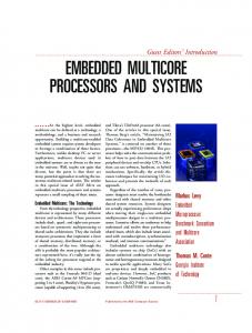
Figure 1. VIRAM prototype processor: block diagram (a), die photo (b).
tor load-store instruction captures the functionality of multiple RISC or CISC instructions for address generation, striding, and indexing. VIRAM’s code is 2.5 to 10 times smaller than that of the VLIW architectures. VIRAM’s main advantage is that the compiler needn’t use loop unrolling or software pipelining for performance reasons, as it must with VLIW processors. VLIW architectures incur the additional penalty of empty slots in their wide-instruction format.
Prototype vector processor We implemented a prototype vector processor to validate the VIRAM architecture’s potential for embedded media processing and as a fast platform for software experimentation. The processor attaches a vector unit as a coprocessor to a 64-bit MIPS core. The VRF has a capacity of 8 Kbytes (32 64-bit, 64 32bit, or 128 16-bit elements per vector register). There are two vector arithmetic functional units, each with four 64-bit ALUs for parallel element execution, and there’s a vector load-store unit with four address generators and a hierarchical TLB. The prototype is actually a system on a chip because it integrates 13 Mbytes of DRAM organized in eight independent banks.
A block diagram of the chip, shown in Figure 1, focuses on the vector hardware and the memory system.3 This design partitions the register and data path resources in the vector coprocessor vertically into four identical vector lanes. Each lane contains several elements from each vector and flag register, and a 64-bit data path from each functional unit. The four lanes receive identical control signals on each clock cycle. The concept of parallel lanes is fundamental for the vector microarchitecture, as it leads to advantages in performance, design complexity, and scalability. VIRAM achieves high performance by using the parallel lanes to execute multiple element operations for each pending vector instruction. Having four identical lanes significantly reduces design and verification time. Lanes also eliminate most long communication wires that complicate scaling in CMOS technology.4 Executing an element operation for all vector instructions, excluding memory references and permutations, involves register and data path resources within a single lane. The scalar core in VIRAM is a single-issue, in-order MIPS core with first-level caches of 8 Kbytes each. The MIPS core supplies the vector instructions to the vector lanes for inorder execution. Vector load and store instruc-
NOVEMBER–DECEMBER 2003
39
MICRO TOP PICKS
Table 2. Characteristics of the embedded processors compared in this study. Instruction Architecture issue Processor type rate VIRAM Vector 1 MPC7455 PowerPC Superscalar 4 Trimedia TM1300 VLIW with SIMD 5 TI TMS320C6203 VLIW plus DSP 8
Execution style In order Out of order In order In order
Cache size Clock Power (Kbytes) frequency dissipation Technology L1I L1D L2 (MHz) (W) (µm) 8 NA NA 200 2.0 0.18 32 32 256 1,000 21.3 0.18 32 16 NA 166 2.7 0.25 96 512 NA 300 1.7 0.13
tions access DRAM-based main memory directly without using SRAM caches. Embedded DRAM is faster than commodity DRAM but still significantly slower than a first-level SRAM cache. The processor operates at a modest 200 megahertz (MHz). The intentionally low clock frequency, along with the in-order, cacheless organization for the vector unit results in a power consumption of only 2 W. These features also contribute to reduced design complexity. Three full-time and three part-time graduate students designed the 125-milliontransistor chip over three years. To hide DRAM latency, both load-store and arithmetic vector instructions are deeply pipelined (15 stages).
Prototype processor evaluation Table 2 compares the VIRAM prototype with three embedded processors whose features represent the great variety in high-performance embedded designs: two basic architectures (out-of-order superscalar and inorder VLIW), a range of instruction issue rates (4 to 8 instructions per clock cycle), varying clock rates (166 MHz to 1 GHz), and differences in power dissipation (1.7 W to 21.3 W). The only common feature of the three embedded processors is their use of SRAM caches for low memory latency. Before comparing performance, let’s look at power consumption and design complexity. The typical power dissipation numbers in Table 2 are not directly comparable because these processors represent different CMOS manufacturing technologies. The VIRAM power figure includes the power for main memory accesses, which is not the case for any other design. In addition, the VIRAM circuits were generated with a standard synthesis flow and were not optimized for low power consumption in any way. The VIRAM chip’s
40
IEEE MICRO
power characteristics are entirely due to its microarchitecture. Nevertheless, we can draw some general conclusions about power consumption. Superscalar, out-of-order processors like the MPC7455 consume the most power because of their high clock rates and the complexity of their control logic. VLIW processors’ simplicity and lower clock frequencies result in reduced power consumption despite their high instruction issue rates. The VIRAM processor’s microarchitecture permits additional power savings. Low clock frequency and the use of exclusively static circuits make the parallel vector lanes power efficient. The simple single-issue, in-order control logic must fetch and decode only one vector instruction to execute tens of element operations, so it dissipates a minimum amount of power. Finally, the onchip main memory provides high bandwidth without wasting power for driving off-chip interfaces or for accessing caches for applications with limited temporal locality. Design complexity is also difficult to compare unless the same work group implements all processors in the same technology with the same tools. However, we believe the VIRAM microarchitecture is significantly less complex than superscalar processors. Both the vector coprocessor and the main-memory system are modular, the control logic is simple, and there is no need for caches or circuit design for high clock frequency. Superscalar processors, on the other hand, include complicated control logic for out-oforder execution, and this is difficult to design at high clock rates. Although VLIW processors for embedded applications are simpler than superscalar designs, the high instruction issue rate makes them more complicated than single-issue vector processors. In addition, VLIW architectures introduce significant
VLIW
VLIW-opt
VIRAM-1L
VIRAM-2L
VIRAM-4L
25
180
20
150 Performance/MHz
Performance/MHz
Superscalar
15
10
5
0
VIRAM-8L
120 90 60 30
Rgb2cmyk
Rgb2yiq
JPEG
Autocor
Bital
0
Viterbi
Filter
Benchmarks (a)
FFT
Convenc
Benchmarks (b)
Figure 2. Performance-per-MHz comparison, normalized to the performance of the MPC7455 superscalar processor. Note the change of scale between the benchmarks in (a) and those in (b).
complexity into compiler development. Figure 2 compares performance per MHz,3 where performance is inversely proportional to the execution time for each benchmark. We normalize the performance for each processor to that of the MPC7455 superscalar processor. We compare performance per MHz because we have no fundamental reason to believe that these processors couldn’t be clocked at the same frequency, given similar design efforts. If raw performance is of interest, it’s easy to scale the results in Figure 2 by the corresponding clock frequency for each design. Interestingly, Figure 2 would look nearly identical if we plotted performance per watt. Along with showing the performance of the actual VIRAM chip with four lanes (VIRAM4L), Figure 2 presents simulated performance for two scaled-down variations of the design, with one and two lanes (VIRAM-1L and VIRAM-2L), and a scaled-up version with eight lanes (VIRAM-8L). Excluding the number of lanes, all parameters are identical. We used the same VIRAM executables with all versions of the VIRAM processor; there was no lane-specific recompilation. For highly vectorizable benchmarks with long vectors, such as Filter and Convenc, VIRAM-4L is up to 100 times faster than
MPC7445. Each vector instruction defines tens of independent element operations, which can use the parallel data paths in the vector lanes for several clock cycles. A superscalar processor, on the other hand, can extract a much smaller amount of ILP from its sequential instruction streams. For benchmarks with strided and indexed memory accesses, such as Rgb2cmyk and Rgb2yiq, VIRAM-4L outperforms MPC7455 by a factor of 10. In this case, VIRAM-4L’s restriction is its address generation throughput for strided and indexed accesses to narrow data types. For partially vectorizable benchmarks with short vectors, such as JPEG and Viterbi, VIRAM-4L maintains a 3× to 5× performance advantage over MPC7455. Even with just 13 elements per vector, simple vector hardware is more efficient with DLP than aggressive, wideissue, superscalar organizations. With the original benchmark code, the two VLIW processors’ performance is similar to or worse than the MPC7455’s. Source code optimizations and the manual insertion of SIMD and DSP instructions lead to significant improvements and enable the VLIW designs with optimized code to be within 50 percent of VIRAM’s performance. TM1300 outperforms VIRAM-4L only for JPEG, for
NOVEMBER–DECEMBER 2003
41
MICRO TOP PICKS
which the TM1300’s performance improves considerably once its designers restructured the benchmark code to eliminate the function call within the nested loop for the discrete cosine transform. The same manual transformation would have benefited VIRAM-4L because it would allow outer-loop vectorization and result in long vectors.
Scaling for data-level parallelism Organizing the vector hardware in lanes provides a simple mechanism for scaling performance, power consumption, and area (cost). With each extra lane, we can execute more element operations per cycle for each vector instruction. This is a balanced scaling method: Each lane includes both register and data path resources. Figure 2 shows the VIRAM processor’s performance as we scale the number of lanes from one to eight, without modifying the scalar core or the memory system. Except for JPEG, performance scales linearly for up to four lanes. Eight lanes are useful for benchmarks with long vectors (Rgb2cmyk, Convenc, and FFT). For benchmarks with mediumlength or short vectors (Viterbi and Bital), eight lanes execute vector instructions so quickly that we can no longer hide the overhead of scalar operations and vector-scalar communication. In other words, VIRAM-8L, a vector configuration with 16 64-bit integer ALUs, is often limited by instruction-issue bandwidth. Comparable scaling results are difficult to achieve with other architectures. Scaling a four-way superscalar processor to eight-way, for example, would probably lead to a small overall performance improvement. It’s difficult to extract such a high amount of ILP, and the wide out-of-order logic’s complexity would slow the clock frequency.5 A VLIW processor could achieve similar scaling after recompilation and manual code reoptimization. The cost in this case would be even larger code and increased power consumption for the wide instruction fetch.
Clustered vector processor Although the VIRAM processor demonstrates vector architectures’ great potential for embedded media processing, VIRAM is still susceptible to the basic limitations of traditional vector designs. The complexity of the VRF partition within each lane is the most significant
42
IEEE MICRO
limitation.6 To support the one load-store and two arithmetic vector units, the 2-Kbyte partition requires nine access ports. In general, with N functional units, the VRF partition requires approximately 3N ports. Its area, power consumption, and access latency are roughly proportional to N2, logN, and N.7 To avoid this complexity, most vector processors include up to four units. However, a larger number of functional units is desirable for applications with short and medium-length vectors, for which multiple lanes do not help with performance. With more functional units, multiple vector instructions could execute in a parallel or overlapped manner, even if their corresponding vectors were relatively short. To alleviate the problem of VRF complexity, we propose replacing the centralized vector-lane organization in the VIRAM processor with a clustered arrangement. Figure 3a shows the centralized organization. In the clustered organization (Figure 3b), each cluster contains a data path for a single vector functional unit and a few vector registers. A separate intercluster network moves vectors between functional units when needed. The local register file block within each cluster provides operands to one data path and one network interface. Hence, the number of access ports for each block is small (four to five) and independent of the number of vector functional units in the system. In other words, the area, power consumption, access latency, and design complexity of each VRF block are constant. To use the clustered organization without modifying the VIRAM instruction set, we employ renaming in the vector hardware’s control logic. A renaming table identifies the cluster that stores the source and destination registers for a vector instruction and indicates whether an intercluster transfer is necessary, given the cluster that will execute the instruction. Renaming also lets us implement more than the 32 vector registers defined in the instruction set architecture. Extra registers make it possible to tolerate long memory latencies or to implement precise exceptions. The vector unit’s control logic must also select the cluster to execute each vector instruction. If multiple cluster assignments are possible, the control logic tries to minimize the number of transfers without creating a significant load imbalance across clusters.
Instructions
Instructions
32 vector registers
ALU
ALU
8 vector registers
Loadstore unit
8 vector registers
ALU
8 vector registers
ALU
8 vector registers
Loadstore unit
Intercluster network (a)
To/from memory
To/from memory
(b)
Figure 3. Vector lane organization: centralized (a) and clustered (b) lane organizations.
Overall, the new control logic’s functionality resembles that of multicluster superscalar processors.8 It is much simpler, however, because maintaining an issue rate of one vector instruction per cycle is sufficient. A superscalar processor, on the other hand, must issue one instruction per functional unit per cycle. The clustered organization in Figure 3b associates a small instruction queue with each cluster. Instruction queues permit decoupled execution.9 As long as there are no data dependencies among the instructions assigned to different clusters, the clusters can execute instructions independently of stalls in other clusters. Decoupled execution can hide memory stalls and the latency of intercluster transfers. Data queues for decoupled execution are not necessary in this case because the vector registers within each cluster provide similar functionality.
Evaluation of clustered vector processor Figure 4 shows the simulated performance improvement if we replace the centralized lane in the VIRAM with the clustered-lane organization. Each lane has four clusters: two for the arithmetic units, one for the load-store unit, and one that provides additional register storage. The intercluster network’s bandwidth is two words per cycle; its latency is two cycles. We assume the new design will have the same clock frequency as the original, despite the much simpler VRF. In theory, the original VIRAM design should always be faster. It uses a centralized VRF
and communicates vector results between functional units without incurring a penalty. The intercluster network, on the other hand, can become a latency or bandwidth bottleneck for a clustered design.10 Nevertheless, Figure 4 shows that the clustered organization is actually faster than the centralized one for many benchmarks. Decoupled execution hides most intercluster transfer latency. It also hides a significant portion of the memory latency for vector accesses that run into memory bank conflicts or address generation limitations (as in Rgb2cmyk, for example). On average, the clustered organization outperforms the centralized one by 21 percent to 42 percent, depending on the number of lanes in the system. The clustered vector organization provides a second scaling dimension for the vector processor. We can scale both the number of lanes and the number of vector functional units (clusters) without complicating the VRF design. Figure 5 presents the benefits from these two scaling techniques. We measure speedup over a clustered vector design with one lane and four clusters (Figure 3b). When increasing the number of functional units, we maintain approximately a 2:1 ratio between arithmetic and load-store vector functional units. Every cluster includes eight vector registers; hence, all configurations with more than four clusters implement more than 32 physical vector registers. Increasing the number of lanes enables the execution of multiple element operations per
NOVEMBER–DECEMBER 2003
43
2 lanes
4 lanes
FFT
1 lane
250
Bital
300 8 lanes
200 150 100 50
Viterbi
Convenc
Autocor
Filter
Rgb2yiq
JPEG
0 −50
Rgb2cmyk
Performance improvement (%)
MICRO TOP PICKS
Figure 4. Performance improvement with the clustered vector organization. The FFT benchmark shows a 0 percent performance degradation.
1 lane
2 lanes
4 lanes
8 lanes
8 7
Speedup
6 5 4 3 2 1 4
6
8
12
16
No. of clusters
Figure 5. Average speedup for the EEMBC benchmarks with scaling of the clustered vector processor.
cycle for each vector instruction in progress. Two lanes lead to a nearly perfect speedup of 2. Four and eight lanes lead to speedups of 3.1 and 4.8. In general, efficiency drops significantly as the number of lanes grows. Applications with very short vectors (for example, Viterbi) cannot efficiently use a large number of data paths. For programs with longer vectors, multiple lanes decrease the execution time of each vector instruction, so hiding the overhead of scalar instructions, intercluster communication, and memory latency becomes more difficult. Increasing the number of clusters permits parallel execution of multiple vector instructions. Using eight clusters provides a 50 percent
44
IEEE MICRO
to 75 percent performance improvement over the four-cluster case, depending on the number of lanes. Yet performance improves little with more than eight clusters, for two reasons. Primarily, it is not possible to use more than eight clusters efficiently with single-instruction issue, especially in the case of multiple lanes. Furthermore, data dependencies and an increased number of memory system conflicts limit the possibilities for concurrent instruction execution. Overall, combining the two scaling techniques improves performance by a factor of approximately 7, using eight clusters and eight lanes (or 42 arithmetic data paths), before it becomes instruction bandwidth limited.
The clustered organization also allows for precise exceptions in the vector processor at a negligible performance cost. Furthermore, clustering permits high performance with main memory systems that exhibit higher access latencies than the embedded DRAM used in the VIRAM prototype. We earlier presented these experimental results in detail.6
T
he VIRAM architecture demonstrates the great potential of vector processors with high-end embedded systems. It exploits DLP to provide high performance with simple hardware and low power consumption. Our current work focuses on architectures that combine vector techniques for DLP and multithreading techniques for task-level parallelism, the other major type of parallelism in embedded applications. Hardware and software development for such hybrid architectures poses a number of exciting research challenges. MICRO Acknowledgments We thank all the members of the IRAM research group at the University of California at Berkeley. IBM, MIPS Technologies, Cray, and Avanti made significant hardware and software contributions to the IRAM project. This work was supported by DARPA (DABT63-96-C-0056) and by an IBM PhD fellowship. References 1. R. Espasa, M. Valero, and J.E. Smith, “Vector Architectures: Past, Present and Future,” Proc. 12th Int’l Conf. Supercomputing, 1998, ACM Press, pp. 425-432. 2. J. Smith, G. Faanes, and R. Sugumar, “Vector Instruction Set Support for Conditional Operations,” Proc. 27th Int’l Symp. Computer Architecture (ISCA 2000), IEEE CS Press, 2000, pp. 260-269. 3. C. Kozyrakis and D. Patterson, “Vector versus Superscalar and VLIW Architectures for Embedded Multimedia Benchmarks,” Proc. 35th Ann. Int’l Symp. Microarchitecture (Micro-35), ACM Press, 2002, pp. 283-293. 4. R. Ho, K. Mai, and M. Horowitz, “The Future of Wires,” Proc. IEEE, vol. 89, no. 4, Apr. 2001, pp. 490-504. 5. V. Agarwal et al., “Clock Rate vs IPC: The End of the Road for Conventional Microarchitectures,” Proc. 27th Int’l Symp. Com-
6.
7.
8.
9.
10.
puter Architecture (ISCA 2000), IEEE CS Press, 2000, pp. 248-259. C. Kozyrakis and D. Patterson, “Overcoming the Limitations of Conventional Vector Processors,” Proc. 30th Int’l Symp. Computer Architecture (ISCA 2003), ACM Press, 2003, pp. 283-293. S. Rixner et al., “Register Organization for Media Processing,” Proc. 6th Int’l Conf. High-Performance Computer Architecture (HPCA 6), IEEE CS Press, 2000, pp. 375-386. K. Farkas et al., “The Multicluster Architecture: Reducing Processor Cycle Time Through Partitioning,” Proc. 30th Ann. Int’l Symp. Microarchitecture (Micro-30), IEEE CS Press, 1997, pp. 327-356. J. Smith, “Decoupled Access/Execute Computer Architecture,” ACM Trans. Computer Systems, vol. 2, no. 4, Nov. 1984, pp. 289-308. J. Fisher et al., Clustered Instruction-Level Parallel Processors, tech. report HPL-98-204, HP Labs, Dec. 1998.
Christoforos E. Kozyrakis is an assistant professor of electrical engineering and computer science at Stanford University. His research interests include parallel architectures and compilation techniques for systems ranging from supercomputers to deeply embedded devices. Kozyrakis has a PhD in computer science from the University of California at Berkeley, where he was the architect of the VIRAM processor. He is a member of the IEEE and the ACM. David A. Patterson teaches computer architecture at the University of California at Berkeley, and holds the Pardee Chair of Computer Science. His work has included the design and implementation of RISC I and the redundant arrays of inexpensive disks (RAID) project. Patterson has a PhD in computer science from the University of California at Los Angeles. He is a fellow of the IEEE Computer Society and the ACM, and a member of the National Academy of Engineering.
Direct questions and comments about this article to Christoforos Kozyrakis, Stanford University, Electrical Engineering Department, Stanford, CA 94304-9030; christos@ ee.stanford.edu.
NOVEMBER–DECEMBER 2003
45