Scaling phenomenon of graphene surface plasmon modes in grating-spacer-graphene hybrid systems Linlong Tang,1,2 Jinglei Du,1,3 Chunlei Du,2,4 Peng Zhu,2 and Haofei Shi2,* 1
2
Key Laboratory of High Energy Density Physics and Technology, College of Physics and Technology, Sichuan University, Chengdu, 610064, China Chongqing institute of green and intelligent technology, Chinese Academy of Sciences, Chongqing, 401122, China 3
[email protected] 4
[email protected] *
[email protected]
Abstract: We investigate the excitations of graphene surface plasmon waves in grating-spacer-graphene hybrid systems. It is demonstrated that the resonant absorption rate is scaling invariant as the geometric parameters of the hybrid system are scaled, and this phenomenon is nearly unaffected by the dispersions of the optical parameters of graphene and the grating material. We present an analytical model to calculate the absorption rate and elucidate that the scaling invariant phenomenon originates from the scalabilities of the graphene surface plasmon modes. This study could benefit the development of graphene plasmonic devices at infrared and terahertz frequencies. ©2014 Optical Society of America OCIS codes: (240.6680) Surface plasmons; (050.6624) Subwavelength structures; (260.5740) Resonance.
References and links 1. 2. 3. 4. 5. 6. 7. 8. 9. 10. 11. 12. 13.
A. N. Grigorenko, M. Polini, and K. S. Novoselov, “Graphene plasmonics,” Nat. Photon. 6(11), 749–758 (2012). L. Ju, B. Geng, J. Horng, C. Girit, M. Martin, Z. Hao, H. A. Bechtel, X. Liang, A. Zettl, Y. R. Shen, and F. Wang, “Graphene plasmonics for tunable terahertz metamaterials,” Nat. Nanotechnol. 6(10), 630–634 (2011). F. H. L. Koppens, D. E. Chang, and F. J. García de Abajo, “Graphene plasmonics: a platform for strong light-matter interactions,” Nano Lett. 11(8), 3370–3377 (2011). M. Jablan, H. Buljan, and M. Soljacic, “Plasmonics in graphene at infrared frequencies,” Phys. Rev. B 80(24), 245435 (2009). Z. Fang, S. Thongrattanasiri, A. Schlather, Z. Liu, L. Ma, Y. Wang, P. M. Ajayan, P. Nordlander, N. J. Halas, and F. J. García de Abajo, “Gated tunability and hybridization of localized plasmons in nanostructured graphene,” ACS Nano 7(3), 2388–2395 (2013). Z. Fei, A. S. Rodin, G. O. Andreev, W. Bao, A. S. McLeod, M. Wagner, L. M. Zhang, Z. Zhao, M. Thiemens, G. Dominguez, M. M. Fogler, A. H. Castro Neto, C. N. Lau, F. Keilmann, and D. N. Basov, “Gate-tuning of graphene plasmons revealed by infrared nano-imaging,” Nature 487(7405), 82–85 (2012). H. Yan, X. Li, B. Chandra, G. Tulevski, Y. Wu, M. Freitag, W. Zhu, P. Avouris, and F. Xia, “Tunable infrared plasmonic devices using graphene/insulator stacks,” Nat. Nanotechnol. 7(5), 330–334 (2012). S. Thongrattanasiri, F. H. L. Koppens, and F. J. García de Abajo, “Complete optical absorption in periodically patterned graphene,” Phys. Rev. Lett. 108(4), 047401 (2012). H. G. Yan, T. Low, W. J. Zhu, Y. Q. Wu, M. Freitag, X. S. Li, F. Guinea, P. Avouris, and F. N. Xia, “Damping pathways of mid-infrared plasmons in graphene nanostructures,” Nat. Photon. 7(5), 394–399 (2013). A. Y. Nikitin, F. Guinea, F. J. Garcia-Vidal, and L. Martin-Moreno, “Surface plasmon enhanced absorption and suppressed transmission in periodic arrays of graphene ribbons,” Phys. Rev. B 85(8), 081405 (2012). J. Chen, M. Badioli, P. Alonso-González, S. Thongrattanasiri, F. Huth, J. Osmond, M. Spasenović, A. Centeno, A. Pesquera, P. Godignon, A. Z. Elorza, N. Camara, F. J. García de Abajo, R. Hillenbrand, and F. H. L. Koppens, “Optical nano-imaging of gate-tunable graphene plasmons,” Nature 487(7405), 77–81 (2012). V. G. Kravets, F. Schedin, and A. N. Grigorenko, “Extremely narrow plasmon resonances based on diffraction coupling of localized plasmons in arrays of metallic nanoparticles,” Phys. Rev. Lett. 101(8), 087403 (2008). T. R. Zhan, F. Y. Zhao, X. H. Hu, X. H. Liu, and J. Zi, “Band structure of plasmons and optical absorption enhancement in graphene on subwavelength dielectric gratings at infrared frequencies,” Phys. Rev. B 86(16), 165416 (2012).
#213816 - $15.00 USD Received 10 Jun 2014; revised 24 Jul 2014; accepted 24 Jul 2014; published 13 Aug 2014 (C) 2014 OSA 25 August 2014 | Vol. 22, No. 17 | DOI:10.1364/OE.22.020214 | OPTICS EXPRESS 20214
14. N. M. R. Peres, Y. V. Bludov, A. Ferreira, and M. I. Vasilevskiy, “Exact solution for square-wave grating covered with graphene: surface plasmon-polaritons in the terahertz range,” J. Phys. Condens. Matter 25(12), 125303 (2013). 15. W. Gao, G. Shi, Z. Jin, J. Shu, Q. Zhang, R. Vajtai, P. M. Ajayan, J. Kono, and Q. Xu, “Excitation and active control of propagating surface plasmon polaritons in graphene,” Nano Lett. 13(8), 3698–3702 (2013). 16. W. Gao, J. Shu, C. Qiu, and Q. Xu, “Excitation of plasmonic waves in graphene by guided-mode resonances,” ACS Nano 6(9), 7806–7813 (2012). 17. X. Zhu, W. Yan, P. U. Jepsen, O. Hansen, N. A. Mortensen, and S. Xiao, “Experimental observation of plasmons in a graphene monolayer resting on a two-dimensional subwavelength silicon grating,” Appl. Phys. Lett. 102(13), 131101 (2013). 18. J. Schiefele, J. Pedrós, F. Sols, F. Calle, and F. Guinea, “Coupling light into graphene plasmons through surface acoustic waves,” Phys. Rev. Lett. 111(23), 237405 (2013). 19. M. Farhat, S. Guenneau, and H. Bağcı, “Exciting graphene surface plasmon polaritons through light and sound interplay,” Phys. Rev. Lett. 111(23), 237404 (2013). 20. Y. V. Bludov, M. I. Vasilevskiy, and N. M. R. Peres, “Mechanism for graphene-based optoelectronic switches by tuning surface plasmon-polaritons in monolayer graphene,” Europhys. Lett. 92(6), 68001 (2010). 21. L. A. Falkovsky and S. S. Pershoguba, “Optical far-infrared properties of a graphene monolayer and multilayer,” Phys. Rev. B 76(15), 153410 (2007). 22. E. D. Palik and G. Ghosh, Handbook of Optical Constants of Solids (Academic, 1985). 23. H. A. Haus, Waves and Fields in Optoelectronics (Prentice-Hall, 1984). 24. J. D. Joannopoulos, S. G. Johnson, J. N. Winn, and R. D. Meade, Photonic Crystals: Molding the Flow of Light, 2nd ed. (Princeton University, 2008). 25. S. H. Fan, W. Suh, and J. D. Joannopoulos, “Temporal coupled-mode theory for the Fano resonance in optical resonators,” J. Opt. Soc. Am. A 20(3), 569–572 (2003). 26. M. Ghebrebrhan, P. Bermel, Y. X. Yeng, I. Celanovic, M. Soljačić, and J. D. Joannopoulos, “Tailoring thermal emission via Q matching of photonic crystal resonances,” Phys. Rev. A 83(3), 033810 (2011).
1. Introduction In recent years, it has become clear that graphene can support low loss, highly localized surface plasmon waves in the mid-infrared and terahertz region [1–4], which is now arousing increasingly research interest. Unlike plasmons in noble metals, graphene plasmons can be dynamically tuned through the modulation of carrier density by electrostatic gating [5–7], making graphene a promising platform for a wide range of active plasmonic devices. One fundamental problem of graphene plasmonics is how to efficiently excite a graphene surface plasmon (GSP) wave with a free space electromagnetic (EM) wave, given that their wavevectors are in huge mismatch. Lately, by patterning graphene into nano-structures [5,8–10] or introducing nano-scatters (nano-tips [6,11], nano-particles [12], sub-wavelength gratings [13–17]) in the vicinity of graphene, the excitations of GSP waves have been demonstrated both theoretically and experimentally. Meanwhile, other excitation schemes based on the interplays between EM waves and acoustic waves [18,19], or employing the total reflections in prisms [20] have also been proposed. Among them, the sub-wavelength grating excitation method possesses many merits: it is very efficient and the graphene need not to be patterned, which preserves the high mobility of graphene and simplifies the doping configuration. These advantages can be exploited for many novel applications, such as tunable terahertz filters, modulators and nonlinear terahertz components. However, due to the complicated couplings of the incident EM wave, the sub-wavelength grating and the graphene, it is difficult to gain insight into the physics of the grating excitation system. Especially, the outstanding questions are still unclear: How to determine the absorption rate from the system parameters, and is there any special relation between the absorption rate and the geometry of the system? Understanding of these could provide guidance for the designs of graphene plasmonic devices. In this paper, we study the excitations of the GSP waves in the grating-spacer-graphene hybrid systems. Based on simulations, we find that the resonant absorption rate has an interesting relation with the geometry of the hybrid system, namely, it is almost scaling invariant as the spacer thickness and grating period are scaled at the same ratio. Moreover, this phenomenon is nearly independent of the dispersions of the optical parameters of the graphene and the grating material, and is also observable in high order GSP modes. To understand the
#213816 - $15.00 USD Received 10 Jun 2014; revised 24 Jul 2014; accepted 24 Jul 2014; published 13 Aug 2014 (C) 2014 OSA 25 August 2014 | Vol. 22, No. 17 | DOI:10.1364/OE.22.020214 | OPTICS EXPRESS 20215
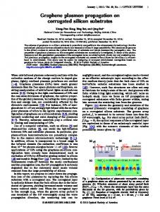
scaling invariant phenomenon, we present an analytical model to reveal the relation between the absorption rate and the system parameters and demonstrate that the phenomenon is caused by the scalabilities of GSP modes. 2. Results A schematic view of the grating-spacer-graphene (GSG) hybrid system under study is shown in Fig. 1. The spacer is placed between the grating and the graphene, and it can be employed to eliminate the non-uniform doping and strains of the graphene induced by the grating. The optical property of graphene can be described by the surface conductivity σ within the random phase approximation. The conductivity is composed of the intraband part σintra and the interband part σinter, i.e. σ = σintra + σinter, and they are given by [21]
σ intra (ω ) =
E f 2e 2T i log 2 cos h , −1 π ω + iτ 2 K BT
e2 ω 4iω ∞ H ( ε ) − H (ω / 2 ) dε . σ inter (ω ) = H + 4 2 π 0 ω 2 − 4ε 2
(1)
In Eq. (1), H ( ε ) = sin h ( ε / K BT ) / cos h ( E f / K BT ) + cos h ( ε / K BT ) , ω is the angular frequency of the EM wave, e is the elementary charge, is the reduced Plank constant, Ef is the Fermi energy, τ is the relaxation time, T = 300 K is the temperature, and KB is the Boltzmann constant. When a transverse magnetic (TM) wave vertically incidents on the grating, its nth diffraction order will gain an extra wavevector 2nπ / l with n being an integer and l the grating period. Then, the nth order GSP mode can be excited by the diffraction order provided Re [q(ω)] = 2nπ / l, where q(ω) is the dispersion relation of the GSP wave with q being its wavevector.
Fig. 1. Schematic of the grating-spacer-graphene hybrid system. The gray region is a grating with period l, height h, and groove width w. The filling factor f of the grating is defined as f = 1-w/l. The blue region is a dielectric spacer of thickness d, and under the spacer is a monolayer graphene. The hybrid system is enclosed by air. The red arrow represents the incident transverse magnetic wave.
We numerically simulate the excitations of GSP modes by two types of gratings, i.e. non-dispersive dielectric gratings and dispersive silver gratings. For every type gratings, the grating periods l are from 200 nm to 600 nm with intervals of 50 nm, and the corresponding spacer thickness d are from 20 nm to 60 nm with intervals of 5 nm. Hence the ratio d / l of every GSG hybrid system is fixed at 0.1, and the equivalence of d / l can be considered as d and l are scaled at the same ratio from one hybrid system to another. The grating heights h are 250 nm, the filling factors are 0.5, the Fermi energies of graphene are 0.2 eV, the relaxation time is 0.64 ps, and the permittivity of air, spacer and the dielectric grating are assumed to be 1, 2.25 and 11.7, respectively. The permittivity of silver is extracted from Palik et al [22].
#213816 - $15.00 USD Received 10 Jun 2014; revised 24 Jul 2014; accepted 24 Jul 2014; published 13 Aug 2014 (C) 2014 OSA 25 August 2014 | Vol. 22, No. 17 | DOI:10.1364/OE.22.020214 | OPTICS EXPRESS 20216
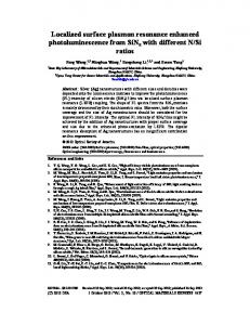
The calculated absorption, transmission and reflection spectrums by finite element method using Comsol Multiphysics for hybrid systems with dielectric and Ag gratings are shown in Figs. 2(a) and 2(b), respectively. Resonant peaks or notches corresponding to the excitations of the first order GSP modes are observed in the spectrums, and the excited GSP mode patterns are shown in the insets. The figures reveal a very intriguing phenomenon that the reflection, absorption and transmission rates at the resonant wavelengths are nearly identical in both dielectric and Ag grating cases. This phenomenon is somewhat unexpected, because graphene and Ag are dispersive materials, so their optical parameters (conductivity or permittivity) are not identical at different resonant wavelengths. We notice the ratios d / l of the hybrid systems are the same and hence the phenomenon may have underlying physics with this geometric parameter.
Fig. 2. The reflection (R), absorption (A) and transmission (T) spectrums for GSG hybrid systems with dielectric gratings (a) and with Ag gratings (b). The insets are norms of x component electric fields of GSP waves for gratings with periods of 400 nm, and only one period is shown. The white dashed lines are the boundaries of gratings, and the red dashed lines are the positions of graphene.
To verify the idea, the impacts of d / l on the phenomenon are investigated. The grating heights h are fixed at 250 nm, and the spectrums for GSG hybrid systems with d / l varied from 0.1 to 0.4 are calculated. For simplicity, in the follows we focus on the absorption rate. In Fig. 3, the resonant absorption rates extracted from the spectrums in dielectric and Ag grating cases are presented. We can see that the rates for hybrid systems with different grating periods but equal ratios d / l are almost identical in both cases. For example, at d / l = 0.2 the absorption rates are in the range of (18.1 ± 0.2)% in the dielectric grating cases and are within (32.2 ± 0.5)% in the Ag grating cases. Therefore, d / l is indeed a fundamental parameter to determine the resonant absorption rates.
#213816 - $15.00 USD Received 10 Jun 2014; revised 24 Jul 2014; accepted 24 Jul 2014; published 13 Aug 2014 (C) 2014 OSA 25 August 2014 | Vol. 22, No. 17 | DOI:10.1364/OE.22.020214 | OPTICS EXPRESS 20217
Fig. 3. The resonant absorption rates for hybrid systems with grating periods from 200 nm to 600 nm, and d / l from 0.1 to 0.4.
We further change the Fermi energy to 0.3 eV, the filling factors to 0.8, grating heights to 300 nm, and d / l to zero (i.e., there is no spacer between graphene and grating) to see if the phenomenon can still be observed. The calculated absorption spectrums for dielectric gratings and the excited GSP mode patterns are shown in Fig. 4. Interestingly, not only the absorption rates of the first order GSP modes are almost identical, the rates of every higher order GSP modes are also nearly invariant. This result indicates the phenomenon is observable in higher order GSP modes, and not sensitive to variations of other parameters of the hybrid system.
Fig. 4. (a) Absorption spectrums for GSG hybrid systems with grating periods varying from 300 to 700 nm with intervals of 100 nm. For every hybrid system, the five resonant peaks from left to right correspond to the excitations of the first to fifth order GSP modes. (b) The mode patterns of the first to fifth order GSP modes.
3. Physical mechanism Based on the above simulations, it becomes clear that the resonant absorption rates are almost scaling invariant in hybrid systems with the same ratio d / l. To understand the scaling invariant phenomenon, we first study how to calculate the rates analytically. According to the temporal coupled mode theory [23–25], the excitation configuration in Fig. 1 can be taken as the sketch in Fig. 5(a) and modeled through the following set of equations: da = − ( iωa + γ 0 + 2γ 1 ) a + 2γ 1 S1+ , dt S1− = 2γ 1 a ,
(2)
S 2 − = − S1+ + 2γ 1 a .
#213816 - $15.00 USD Received 10 Jun 2014; revised 24 Jul 2014; accepted 24 Jul 2014; published 13 Aug 2014 (C) 2014 OSA 25 August 2014 | Vol. 22, No. 17 | DOI:10.1364/OE.22.020214 | OPTICS EXPRESS 20218
Here a is the amplitude of a resonant GSP mode, normalized such that |a|2 equals the energy of the mode, and ωa is the resonant frequency. γ0 characterizes the intrinsic loss of the GSP mode due to material absorptions, and γ1 is the leakage rate of the GSP mode into the reflected wave or the transmitted wave. S1+, S1- and S2- represent the amplitudes of the incident, reflected and transmitted waves, respectively.
Fig. 5. (a) Schematic of the temporal coupled mode theory description of the excitation configuration. The meaning of the quantities appearing in Eq. (2) is illustrated. (b) The numerical (circle) and analytical (solid line) R, A, T rates for hybrid systems with grating periods l = 250 nm and d / l = 0.1. In the analytical calculations using Eqs. (3)–(5), γ0 = 0.78 THz, γ1 = 0.15 THz for the case of dielectric grating, and γ0 = 0.78 THz, γ1 = 0.33 THz for the case of Ag grating.
From Eq. (2), we can obtain the reflection rate R and the transmission rate T, R=
S1− S1+
S T = 2− S1+
2
= 2
4γ 12
,
(3)
(ω − ωa ) + γ 02 = . 2 2 (ω − ωa ) + (γ 0 + 2γ 1 )
(4)
( ω − ωa )
2
+ ( γ 0 + 2γ 1 )
2
2
The absorption rate A should fulfill energy conservation requirement, A + R + T = 1, hence we get A=
4γ 0γ 1
. (5) 2 + ( γ 0 + 2γ 1 ) To find out these rates, the value of γ0 and γ1 should be specified. If the interband conductivity σinter is negligible compared to the intraband conductivity σintra, γ0 has a simple relation with the relaxation time τ, i.e. γ0 ≈1 / (2τ). The leakage rate γ1 can be calculated numerically [26]. In Fig. 5(b), the analytical results given by Eqs. (3)–(5) are compared with those of simulations. Clearly, the two kind results are in excellent agreement in both dielectric and Ag grating cases, indicating the hybrid system can be well described by the temporal coupled mode theory. Equations (3)–(5) show that at resonant frequencies (i.e., ω = ωa), the rates R, A, T only depend on γ0 and γ1. Notice that γ0 of every hybrid system are the same because the relaxation time τ are unchanged in the simulations. Therefore, the scaling invariant phenomenon of the rates implies that the γ1 of the hybrid systems with the same d / l should be equal, and we indeed find the γ1 are nearly identical by numerically calculate them. Since γ1 represents the leakages of the GSP modes into free space waves, hence the equivalence of γ1 requires the GSP mode patterns to be similar to each other. In other words, the scaling invariant phenomenon is caused by the scalabilities of GSP mode patterns.
( ω − ωa )
2
#213816 - $15.00 USD Received 10 Jun 2014; revised 24 Jul 2014; accepted 24 Jul 2014; published 13 Aug 2014 (C) 2014 OSA 25 August 2014 | Vol. 22, No. 17 | DOI:10.1364/OE.22.020214 | OPTICS EXPRESS 20219
As an illustration of this idea, the GSP mode patterns in hybrid systems with identical d / l but different l in dielectric and Ag grating cases are shown in Figs. 6(a) and 6(b), and it is obvious that the mode patterns are similar in both cases.
Fig. 6. Mode patterns for dielectric gratings with d / l = 0.4 (a) and for Ag gratings with d / l = 0.1 (b). The numerical and analytical GSP resonant wavelengths (c). Di and Ag represent the hybrid systems with dielectric and Ag gratings, respectively.
Now we study the GSP modes quantitatively to understand why the mode patterns can be scaled to each other. For simplicity, the grating is approximated by an infinite thick uniform medium with effective permittivity ε1 = (2 − f + εg f) / 2, where f and εg are the filling factor and the permittivity of the grating material, respectively. Then the magnetic field of a GSP mode can be written as (y > d) H1 exp ( iqx + ik1 y ) + − H z = H 2 exp ( iqx + ik2 y ) + H 2 exp ( iqx − ik2 y ) (0 < y < d ) , H exp ( iqx − ik y ) ( y < 0) 3 3
(6)
where H1 , H 2+ , H 2− , H 3 are field amplitudes of the GSP mode, and kj = [εj (ω / c)2 - q2]1/2 with εj being the permittivity of the effective uniform medium, spacer and air when j = 1, 2 and 3, respectively. By matching the boundary conditions at y = 0 and d, we obtain the ratios between field amplitudes H ε H+ H 2+ ε1 + ε 2 H H+ exp ( 2qd ) , 1− = 2− + exp ( 2qd ) , 3− = 3 1 − 2− , = − H 2 ε1 − ε 2 H2 H2 H2 ε2 H2
(7)
and the dispersion relation q=i
(ε + ε ) exp ( 2qd ) + (ε1 − ε 2 ) ω ε 0 ε 3 + ε 2 1 2 . σ (ω ) (ε1 + ε 2 ) exp ( 2qd ) − (ε1 − ε 2 )
(8)
In the derivations, we have employed the approximation k1 ≈ k2 ≈ k3 ≈ iq [4]. Equation (6) manifests that the mode pattern is determined by H1 : H 2+ : H 2− : H 3 . Therefore, if two GSP modes can be scaled to each other, their H1 : H 2+ : H 2− : H 3 should be equal. This requirement can be fulfilled when the H 2+ / H 2− of the two modes are the same according to Eq. (7). For a GSP wave excited by the nth diffraction order of a grating, we have Re (q) = 2nπ / l. Then, if Re (q) is used to approximate q, H 2+ / H 2− can be rewritten as H 2+ ε1 + ε 2 d exp 4nπ . = − l H 2 ε1 − ε 2
(9)
#213816 - $15.00 USD Received 10 Jun 2014; revised 24 Jul 2014; accepted 24 Jul 2014; published 13 Aug 2014 (C) 2014 OSA 25 August 2014 | Vol. 22, No. 17 | DOI:10.1364/OE.22.020214 | OPTICS EXPRESS 20220
On the basis of this equation, the scaling invariant phenomenon can be understood. For dielectric gratings, ε1 is a constant and H 2+ / H 2− is determined only by the ratio d / l. Therefore, the GSP modes between hybrid systems with the same ratio d / l are scalable. For Ag gratings, ε1 is no longer a constant due to the dispersion of Ag. However, the absolute value of ε1 is much larger than ε2 (e.g., ε1 ≈-677 + 352i at 10 μm, while ε2 is 2.25.), thus in Eq. (9) (ε1 + ε2) / (ε1- ε2) ≈1. Again, H 2+ / H 2− only has a dependence on d / l. This is the reason why the scaling invariant phenomenon is not sensitive to the dispersion of Ag as observed in Figs. 2 and 3. The conductivity σ of graphene only affects the excitation frequency ω and the imaginary part of q according to Eq. (8), indicating the dispersion of graphene has negligible impact on H 2+ / H 2− and therefore the scaling invariant phenomenon. The simulation results in Fig. 4 can also be explained by Eq. (9) because the equation shows not only the first order GSP modes (n = 1 in Eq. (9) are scalable, higher orders (n = 2, 3, 4…) should also have this property. In addition, we extracted the numerical resonant wavelengths in Fig. 2 and compared them with the results calculated by the analytical dispersion relation Eq. (8). It is found that the two results match well as displayed in Fig. 6(c), which suggests approximating a grating by a uniform medium with the effective permittivity is acceptable. 4. Discussion
In practical applicaitons, the grating heigh is an important parameter and hence its impact on the resonant absorption rate is investigated. As an example, we calculated the absorption rates for hybrid systems with dielectric gratings of periods 200 nm and heights varying from 300 nm to 10 nm. As shown in Fig. 7(a), the absorption rate is nearly unaffected when the height is reduced from 300 nm to 100 nm, but drops considerably as the heigh is further reduced. To understand this result, the GSP mode patterns for grating heigh of 300 nm, 100nm and 10 nm are displayed in the figure. We can see that the mode patterns for grating height of 300 nm and 100 nm are similar to each other, implying the leakage rate γ1 is nearly unchanged and hence the absorption rate is unaffected. In contrast, the mode pattern for grating height of 10 nm is different from the previous two patterns, resulting in the altering of γ1 and the absorption rate. Based on this analysis, it is clear that the variation of the grating height has negligible influence on the resonant absorption rate as long as the grating is thick enough so that the GSP mode pattern is nearly unaffected.
Fig. 7. (a) The variation of resonant absorption rate with grating height. The white dashed lines in the insets are the boundaries of gratings. (b) The dependence of absorption rate and 2γ1 on the spacer thickness. The two red ellipses indicate the intersections between 2γ1 and γ0 = 0.78, 0.2THz.
The dependence of the resonant absorption rate on the spacer thickness d is also studied. In Fig. 7(b) the computed results are presented, where the curve marked by triangles is the absorption rates for hybrid systems with grating periods of 200 nm, spacer thicknesses varying from 90 nm to 0 nm, and the graphene relaxation time τ is 0.64 ps (i.e., γ0≈0.78 THz). The curve labeled by squares is the absorption rates for the same series of hybrid systems except that the relaxation time τ is now 2.56 ps (i.e., γ0≈0.2 THz). The two curves exhibit similar behaviors. #213816 - $15.00 USD Received 10 Jun 2014; revised 24 Jul 2014; accepted 24 Jul 2014; published 13 Aug 2014 (C) 2014 OSA 25 August 2014 | Vol. 22, No. 17 | DOI:10.1364/OE.22.020214 | OPTICS EXPRESS 20221
Namely, as the spacer thicknesses decrease from 90 nm to 0 nm, the absorption rates first increase till reach a maximum value of 50% and then drop gradually. However, the spacer thicknesses at the maximum absorption rates are different for the two curves. For the triangle marked curve the thickness is 10 nm, while for the square marked curve the thickness is 35 nm. These results can be readily explained by Eq. (5) because the equation shows the resonant absorption rate should always smaller than 50%, and only when 2γ1 = γ0 the rate can reach 50%. To confirm this, we calculated the leakage rate γ1 and plotted 2γ1 in Fig. 7(b), which clearly shows 2γ1≈0.78 THz at d = 10 nm and 2γ1≈0.2 THz at d = 35 nm. Therefore, it can be concluded that there exists a spacer thickness which makes the absorption rate the largest, and the thickness depends on the graphene relaxation time τ. For the graphene grown by chemical vapor deposition method, the τ is relatively short and hence 2γ1 is normally smaller than γ0. Under this circumstance, the maximum absorption rate is reached when the spacer thickness is zero. The absorption rate can be improved to 100% by adding a thick metal as a back mirror in the hybrid system, and a similar case has been investigated [8]. Besides the grating height and the spacer thickness, the filling factor of a grating will also influence the leakage rate γ1 of a GSP mode, hence allowing more degrees of freedom to be explored in designing graphene plasmonic devices. At last, it is worthwhile to point out that the resonant absorption rate is no longer scaling invariant if the interband conductivity σinter is comparable to the intraband conductivity σintra. Because in this case the intrinsic loss rate γ0 cannot be approximated by 1 / (2τ) any more, but should be written as γ 0 = ω 2π 2 Re (σ inter ) / e 2 E f + 1 / τ / 2 + 2ωπ 2 Im (σ inter ) / e 2 E f which is not a constant due to its dependence on ω. The intrinsic loss rate γ0 changes as well if the resonant wavelength is smaller than the wavelength corresponding to the graphene optical phonon loss threshold (i.e., if λa < 6.2 μm) [4], and in this situation the resonant absorption rates are not scaling invariant either. 5. Conclusion
In summary, we have studied the excitations of GSP waves in GSG hybrid systems with both dielectric and silver gratings. It is shown that the resonant absorption rate is scaling invariant as the spacer thickness d and grating period l are scaled at the same ratio, and the phenomenon is nearly independent of the dispersions of silver and graphene, the variations of the Fermi energy and the filling factors of gratings. We presented an analytical method to calculate the absorption rate based on temporal coupled mode theory, and demonstrated that the scaling invariant phenomenon results from the scalabilities of GSP modes. Moreover, it is found that the variation of the grating height has little effect on the absorption rate for a thick grating, but the spacer thickness can influence the rate considerably. Acknowledgments
This work was supported by NSFC (61377054, 11374359, 61275061), Foundation of Collaborative Innovation (XTCX2013002), Natural Science Foundation of Chongqing CSTC (cstc2012jjjq90001, cstc2012ggC50003), and fundamental & advanced research projects of Chongqing (cstc2013jcyjC00001).
#213816 - $15.00 USD Received 10 Jun 2014; revised 24 Jul 2014; accepted 24 Jul 2014; published 13 Aug 2014 (C) 2014 OSA 25 August 2014 | Vol. 22, No. 17 | DOI:10.1364/OE.22.020214 | OPTICS EXPRESS 20222