Scanpath Clustering and Aggregation Joseph H. Goldberg and Jonathan I. Helfman Applications User Experience Oracle USA
[email protected];
[email protected] Abstract Eye tracking specialists often need to understand and represent aggregate scanning strategies, but methods to identify similar scanpaths and aggregate multiple scanpaths have been elusive. A new method is proposed here to identify scanning strategies by aggregating groups of matching scanpaths automatically. A dataset of scanpaths is first converted to sequences of viewed area names, which are then represented in a dotplot. Matching sequences in the dotplot are found with linear regressions, and then used to cluster the scanpaths hierarchically. Aggregate scanning strategies are generated for each cluster and presented in an interactive dendrogram. While the clustering and aggregation method works in a bottom-up fashion, based on pair-wise matches, a top-down extension is also described, in which a scanning strategy is first input by cursor gesture, then matched against the dataset. The ability to discover both bottom-up and top-down strategy matches provides a powerful tool for scanpath analysis, and for understanding group scanning strategies.
data, to identify aggregate scanning strategies within and among observers, groups, and conditions.
1.1
Scanpaths
Most eye trackers sample gaze locations 50-120 times a second, then reduce the samples to sequences of fixations and saccades called ‘scanpaths.’ Several algorithms are available for this reduction [Salvucci and Goldberg 2000]. Scanpaths are essentially records of visual attention while performing a task. Scanpaths are typically represented as a single visual image with a sequence of connected nodes and edges, where node diameter is often displayed as proportional to fixation duration (within defined minimum and maximum bounds) and edges connect successive fixations. Figure 1 displays a hypothetical scanpath with 5 fixations and 4 saccades. Scanpath tracings from real data can be quite complex, with frequent revisiting of AOIs and overlapping saccades.
CR Categories: H.5.2. User Interfaces: Evaluation/methodology, /Theory and methods, I.5.3. Pattern Recognition: Clustering/ algorithms, I.5.5. Pattern Recognition: Implementation/Interactive systems
Keywords: Eye Tracking, Usability Evaluation, Pattern Analysis, Dotplot, String Analysis, Sequential Clustering, Sequence Analysis 1
Introduction
Eye tracking studies collect large amounts of fixation and saccade data while observers complete tasks or view scenes. To improve the design of software and visual media, investigators make usability inferences by comparing task or interface conditions between groups of users. The challenge for the researcher is to quickly comprehend both individual and group scanning strategies in each tested condition. The number of studies using eye tracking methods have increased dramatically in the past few years, due to improvements in hardware, ease of calibration, and rapidly reported results. While new eye-tracking technologies have solved many niggling issues, there is still a significant gap between the results and a real understanding of users’ visual strategies while solving tasks. The present paper proposes a method to cluster users’ scanning
Figure 1. Scanpath showing a sequence of fixations and saccades. Longer fixation durations are denoted by larger diameter circles.
1.2
Areas of Interest
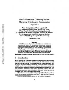
Areas of interest (AOIs) are regions that associate scanpath data with features of the scanned scene, including task target areas. Recent studies have defined AOIs, for example, as separate listings on a search results page [Cutrell and Guan 2007] and as lines of text [Beymer and Russell 2005]. Scanpath data is typically combined with a set of AOIs by determining the containment of fixations within AOIs. AOI statistics can include fixation time within AOIs, time to first view an AOI, order of AOI viewing, transitions among AOIs, time to reach specific AOIs, and other data. Figure 2 illustrates the relationship between scanpaths and AOIs. It shows a design wireframe with 5 AOIs, A-E, and a background area, F. Two scanpaths are shown. One scanpath, shown as solid red, contains 9 fixations. When each fixation is represented by its AOI identifier, the solid red scanpath’s fixations form the sequence: CCABDFEFF. The other scanpath, in dashed blue, contains 8 fixations, which form the sequence: DCDABFEE. Note that some analysis methods eliminate repeated, consecutive AOI visits, and may also eliminate background areas, which would reduce these strings to CABDE and DCDABE,
respectively. Although not immediately obvious, the two scanpaths share the sequence of AOIs: CABFE. Techniques for identifying shared sequences (also called ‘sequential matches’ or ‘alignments’) are described in the following section.
Sequence alignment techniques first attempt to align sequences as closely as possible, before computing their dissimilarity [Josephson and Holmes 2002]. Alignment techniques, however, depend on initial pair-wise alignments and have difficulties aligning sequences of vastly different lengths or with very long distinct subsequences [Higgins, et al. 1996]. Scanpath sequences typically consist of AOI names as tokens, but other tokens are also possible, such as:
Figure 2. Two hypothetical scanpaths browsing a page with six defined AOIs. Each scanpath started at the ‘+’. AOIs may overlap or may be nested within each other. When AOIs overlap it is still possible to establish a process for determining which AOI corresponds to a particular fixation. One such process, for example, is to sort AOIs by area, smallest first, and then iterate through the sorted list, stopping at the first (i.e. the smallest) AOI containing the fixation. Spatial clustering techniques can also be used to empirically define AOIs [Salvucci and Goldberg 2000], in one case from over 5000 scanpaths [Wooding 2002]. A mean shift approach can generate AOIs by iteratively moving sampled gaze locations to locations of higher gaze density on a page [Santella and DeCarlo 2004]. Similarity coefficients within and between participants and images can then be used to generate a parsing tree to assign AOIs automatically [Heminghous and Duchowski 2006].
1.3
Comparing and Aggregating Scanpaths
Although individual scanpaths can appear to be extremely random and noisy, methods are available to compare them, and to aggregate them to find group trends or to uncover cognitive strategies. String comparison methods are often used to compute the similarity between two scanpaths. Scanpaths are first coded as a string of AOI names, numbers or letters. The Levenshtein distance between the strings is then computed as the minimum number of substitutions, insertions, and/or deletions required to transform one string into the other [Levenshtein 1966; Smith and Waterman 1981]. Dynamic programming methods have been used to help determine minimum Levenshtein distances between scanpath sequences [Josephson and Holmes 2002]. A cost is assigned to each of the operations to result in a dissimilarity value that ranges from 0 (identical scanpaths) to 1 (completely different scanpaths). For example, Figure 2’s blue scanpath (DCDABFEE) can be transformed into the red scanpath (CCABDFEFF) with 5 substitutions and 1 addition, a total of 6 operations. Costs may be differentially assigned to each operation type, but can be difficult to define objectively, especially when scanpaths are of vastly different lengths.
•
Saccade Angles. By coding each successive saccade as an angular direction of travel, path direction sequences can be compared. The direction of travel could be measured in either absolute angles (with respect to a common coordinate system) or relative to the current direction of motion.
•
Fixation Durations. Longer fixation durations may indicate greater stimulus complexity or observer confusion [Goldberg and Kotval 1999; 1998]. Scanpaths with longer fixation durations may indicate problematic aspects of an interface.
•
Saccade Distances. Coding the distances between fixations as tokens could potentially locate denser areas of interfaces that result in very short saccades.
Finding scanpath differences among groups of users and conditions is somewhat more difficult than comparing two scanpaths. One algorithm first computes the pairwise sequence alignment difference between scanpaths within each compared group, then computes the difference between groups. A reference distribution is generated by Monte Carlo simulation, allowing the definition of statistically significant differences among scanpaths [Feusner and Lukoff 2008]. Matching alignments from multiple sequences may also represent the ‘averaged’ scanpath from a set of users [Hembrooke, et al., 2006]. Unsupervised learning algorithms can classify natural groups of scanpath sequences, forming a hierarchical clustering of sequences in a hierarchy tree [West, et al. 2006]. Hidden Markov modeling has been used to model scanpaths, by developing probability distributions for sequences of AOI transitions [Salvucci and Goldberg 2000]. While these models can determine the overall transition probabilities among AOIs, the composite probabilities don’t necessarily represent the aggregate sequence across observers. This is due, in part, because Hidden Markov models are usually only first or second order, including only the prior one or two fixations in successive probability estimates [Josephson and Holmes 2002]. Aggregate representations of group sequential scanning strategies are not easily developed from current methods. While heatmaps provide a view of aggregated visual attention over a specific time period, they cannot adequately convey user and group scanning strategies. A single heatmap cannot show changes over time and, therefore, cannot show sequential information about scanpath fixations. Sequential analysis of scanpaths is required to understand the flow of visual attention on a task. Current scanpath comparison and aggregation methods suffer from several drawbacks: •
Scanpath Length. Scanpaths of different lengths have very different similarity scores, and comparison of scanpaths of differering lengths can throw off alignment calculations.
•
Intervening Tokens. In some cases, different length scanpaths are due to non-matching tokens that interrupt what would otherwise be long matching sub-sequences.
•
Transformation Costs. The relative cost of string operations is hard to define objectively, and can greatly alter the similarity metric.
•
Scaling. String analysis methods work well for comparing a limited number of sequences, but they don’t scale effectively to comparisons of all scanpaths in all conditions of a study.
•
Sequential Aggregation of Multiple Scanpaths. While heatmaps aggregate positional fixation information, they do not represent sequential scanning sequences effectively.
1.4
Advantages of dotplots over string editing and alignment techniques include: •
Dotplots do not require a cost matrix to judge the similarity between two strings.
•
Dotplots support the calculation of millions of matches at near interactive rates by pre-computing positions and frequencies of distinct tokens [Church and Helfman 1993].
•
Dotplots provide a visual representation that is useful for interactive exploration and validation.
•
Doplots can robustly handle non-matching tokens that interrupt what would otherwise be long matching subsequences.
2.1
The pair-wise comparison of scanpaths is scaled to an entire study by: (1) concatenating the scanpath AOI sequences into one sequence, (2) plotting the sequence with a dotplot, and (3) using linear regression to identify pair-wise matches in the plot. Large datasets result in a dense dotplot, such as that shown in Figure 4. Green lines indicate boundaries between scanpaths. Red lines indicate a sequential match between two scanpath segments. The dotplot is symmetric, so only matches in the upper half are shown. The plot density has also been relieved somewhat using inverse frequency weighting, in which extremely frequent matches (e.g., revisits to the background AOI) have been downweighted [Church and Helfman 1993].
Dotplots
A dotplot is a graphical technique for visualizing similarities within a sequence or between two or more concatenated sequences. Dotplots have been used to find insertions, deletions, matches, and reverse matches in genetic sequences [Huang and Zhang 2004], and have been applied to finding repetition in literature, detecting plagiarism, aligning translated documents, and identifying copied source code [Church and Helfman 1993; Helfman 1994]. The dotplot can also be considered as an intermediate representation that is used for finding patterns algorithmically; it does not need to be exposed to an eye tracking researcher directly.
2
that smaller AOIs will result in greater precision for representing the aggregate strategy.
A.
B.
Figure 3. Finding matching sequences using a dotplot. A. Dotplot of sequences from Figure 2, with collinear data forming a matching sequence. B. Aggregate strategy sequence ‘CABFE’ plotted on task background. Additional dotplots may contain only selected scanpaths. An example is shown in Figure 5. Regression lines are again shown in red, with stronger matching (i.e., a greater number of matching AOI names) noted by darker cell backgrounds. Regressions with negative slopes indicate forward matching patterns (e.g., CABFE from Figure 3). Positive slopes indicate reverse matching patterns (e.g., EFBAC).
Pattern Analysis Method Sequence Matching using Dotplots
Dotplots can be applied to pattern finding among scanpaths by listing one sequence of scanpath AOI names on the horizontal axis, and one sequence on the vertical axis of a matrix. A dot is placed in the intersecting cells of any matching AOIs. Figure 3A shows an example of a dotplot for the scanpaths from Figure 2. The red scanpath sequence (CCABDFEFF) is plotted on the horizontal axis, and the blue sequence (DCDABFEE) is on the vertical axis of the matrix. A linear regression identifies a sequence of five dots, representing the sequence of matching AOIs, CABFE. An aggregate scanning strategy can now be represented by the sequence of matching AOIs, with each aggregate fixation located near the center of its associated AOI (Figure 3B). Note
Figure 4. Dotplot resulting from concatenated sequence of scanpaths across study participants. Green lines separate each scanpath, and red marks indicate matching sequences.
The matching sequences that are discovered by the dotplot regression now become a reference for hierarchical clustering and aggregation. The dotplot and its matches need only be computed once for a dataset, a computational advantage.
2.3
Hierarchical Strategy Clustering
Matching scanpaths can be hierarchically clustered to find strategies – sets of scanned regions that match increasingly greater numbers of scanpaths and individuals. The process starts by considering every individual scanpath as a leaf node cluster. At each iteration of the process, the two ‘closest’ clusters are merged into a single cluster. Clustering ends when only one cluster remains. The concept of ‘closeness’ is determined from the dotplot matches between the sequences associated with each cluster according to Algorithm 1. Because closeness between clusters must be determined repeatedly, the algorithm includes a basic optimization: closeness results between a pair of clusters are cached using a key formed from the two cluster IDs, and closeness is only calculated if it is not already in the cache. Algorithm 1. Computation of cluster distance.
Figure 5. Subset of previous dotplot, showing matching sequences as red lines. Darker cells represent those patterns that matched a greater number of AOI names.
if(no matches between cluster sequences) distance = MAXIMUM;
//not close
else distance =
2.2
Regressions on Dotplots matchLength/maxMatchLength;
Like heatmaps and other research-oriented visualizations, dotplots show patterns that are recognized by the human visual system quickly, but are much less discernable to a machine. The present approach uses linear regression to pull out statistically significant sequence matches from a dense dotplot. It uses adjustable threshold R2 and residual data distances to find significant matches, as follows: 1.
Start with an inverse-frequency filtered dotplot comparing multiple concatenated scanpath sequences.
2.
Iterate over the dotplot cells for each pair of scanpaths, identifying the ‘darkest’ dots in the cell, which correspond to sub-sequences with significant matches. High-pass frequency thresholds of 0.1-0.5 work well, using a 1µ+1σ criterion.
3.
Fit a linear regression to the darkest points, moving to the next cell if R2 value is too low (e.g.,