scenario, animation. 1 Introduction. The success of visual modeling techniques in computer science and engineering resulted in a variety of meth- ods and ...
Journal on Software & System Modeling manuscript No. (will be inserted by the editor)
Scenario Animation for Visual Behavior Models: A Generic Approach Claudia Ermel, Roswitha Bardohl? Institut f¨ ur Softwaretechnik und Theoretische Informatik Technische Universit¨ at Berlin, Germany E-mail: {lieske, rosi}@cs.tu-berlin.de Received: date / Revised version: date
Abstract Visualizing and simulating the behavior of formal models in an adequate and flexible way becomes increasingly important for the design of complex systems. With GenGED, a tool is available which automatically generates a visual environment to process (create, edit, check, simulate) visual models over a specified visual language. Both the specification of the formalism and the model manipulation are based on graph grammars. In this paper, we present the means to transform an abstract formal behavior model into different application oriented views, called scenario views. We show how the behavior model is consistently transferred to the views and animated there, i.e. simulated in the layout of the application domain. The extension of GenGED to an environment capable of scenario view definition and animation is discussed. Keywords: GenGED, visual modeling languages, graph transformation, visual modeling environment, simulation, scenario, animation
1 Introduction The success of visual modeling techniques in computer science and engineering resulted in a variety of methods and notations addressing different application domains and different phases of the development process. To tackle the problem of increasing complexity in modeling formalisms and in establishing the required tool support for all variants of visual notations, meta-modeling concepts for specifying visual modeling languages (VLs) have been developed like e.g. the UML meta model [31]. The advantages of having a meta model for a specific VL are clear: it allows the automatic generation of ? This work is supported by the German Research Foundation (DFG) in the project “Application of Graph Transformation to Visual Modeling Languages” (DFG Eh 65/8-3).
a tool to build and check models according to the described VL syntax. Instead of programming a complete editor and simulator for a specific VL from scratch, it is only necessary to specify the kind of models we will deal with. The generated tool should be able to allow the construction of valid diagrams (VL diagrams which are instances of a specific VL) in an editor component and, if dynamic system behavior is modeled, to perform simulation of the modeled behavior in a simulator component. A VL model in our approach therefore consists of a set of VL diagrams representing the different states of a system during simulation. The GenGED approach and environment for specifying visual languages and generating visual environments to edit and simulate models visually has been developed at the TU Berlin [2]. Some examples for visual languages defined in GenGED which model the behavior of systems, are statecharts [5], different types of Petri nets [21] or deterministic automata [4]. Despite the benefits, the simulation of VL models is often ineffective in the user validation process. The behavior of a VL model based on (semi-) formal and abstract notations may not always be comprehensible to users and thus makes the requirements validation process less effective. Consequently, we need a modeling technique that on the one hand – is as formal as possible to avoid ambiguities and – allows the systematic construction of (partial) specifications, and on the other hand – describes requirements (and the model behavior) in a way that customers can easily understand and validate them, – supports early detection of inconsistencies and possible requirements missing in the model. Scenarios are a new way of representing system requirements. In a scenario, a part of the system is described by a sequence of state changes caused by events
2
such as user-system interactions. Scenarios were first used in the field of human-computer interaction [13]. Meanwhile they receive considerable attention in requirements engineering [24,33]. In his paper about play-in scenarios [26], Harel proposes to uses ”play-in scenarios” to set up the requirements by ”teaching” the modeling tool about the desired and undesired scenarios. During the process of playing-in scenario-based requirements, the underlying tool should automatically and incrementally generate rigorous models that are consistent with these teachings. Although this thought is intriguing, a lot of research has to be done not only on the algorithmical side but also concerning the human aspect as to which are easy-to-use means to tell a ”behavior-free” system shell what we want from it. The other, more common use of scenarios Harel describes, is the execution (simulation) of the system model which is done by ”playing-out” scenarios to verify the model against the requirements. In Catalysis [18], a methodology for the development of object- and component-based systems, scenarios are visualized by before-and-after snapshots of object diagrams where an action occurs between the two snapshots. Sets of actions (action types) are described by informal textual statements (action specifications) where the effects of the actions are given by pre- and post conditions on the object diagram. In GenGED, the specification of model behavior in the sense of action types is done visually by graph rules called simulation rules. The application of a simulation rule to a concrete VL diagram (simulation step) corresponds to an action in Catalysis, and the VL diagrams modeling system states before and after the rule application can be seen as before-and-aftersnapshots of an action. The simulation of VL models in GenGED is depicted in the upper half of Fig. 1. A sequence of simulation steps defines a scenario of the VL model. The aim of this paper is to further facilitate the user validation process for behavior models in an vieworiented fashion. We present a new concept for systematically generating so-called “scenario views” from VL models. A scenario view presents a scenario of the VL model in the layout of a specific application domain. The consistent transformation of a formal behavior model to the respective scenario view is based on the GenGED approach. We call the simulation steps of a VL model animation steps when the VL diagrams before and after a simulation step are shown in the scenario view. By the transformation of a VL model to a scenario view, the view might show only some aspects or parts of the system. Different views can reflect (parts of) the behavior defined in the VL model. Fig. 1 sketches the relation between VL models (whose VL diagrams are instances of a meta model, i.e. a VL specification) and scenario views in different application domains. View transformation is applied to the VL model, thus realizing a consistent mapping of simulation steps to animation steps in the respective scenario view. Conse-
Claudia Ermel, Roswitha Bardohl Meta Model of a VL VL Model 1
VL Model 2
state state state
state state state
Simulation Step
Simulation Step
View Transformation
... View 1.1 state state state Animation Step
... View 1.n state state state
Animation Step
View 2.1 state state state Animation Step
View 2.n state state state Animation Step
Fig. 1 Different views on formal models
quently, requirements can be interactively demonstrated and clarified in the scenario view helping to produce an improved VL model. For certain modeling formalisms, such as Petri nets, there are tools supporting model animation (see e.g. the SimPEP-tool for the animation of low-level nets in PEP [25]). In contrast to such formalism-based approaches, the generic framework GenGED offers a basis for a more general formalization of VL model behavior which is applicable to various Petri net classes and other visual modeling languages. Tools describing formalisms based on meta-modeling such as DOME [16] or KOGGE [28] are more related to our approach, but they usually allow only some kind of textual language to define the meta model and to express a model’s behavior. We feel that visual means (such as graphs and graph grammars) are more adequate to express features of visual languages and visual models. In the area of visual language definition based on graph transformation, the following tool environments for visual modeling come closest to our approach but do not support scenario views for specific application domains: – DiaGen [29] is based on hyper-edge graph grammars. Visual editors and simulators can be generated. – MetaEnv [11] is an environment to define the semantics for visual models. A visual model which has been defined by an external CASE tool is translated to its semantic domain (High Level Timed Petri Nets) using graph grammars. The semantic model can be simulated, translated into C code and animated (the Petri net firing steps are translated back to the original visual diagram notation). – In ATOM3 [17], the syntax of visual modeling languages is defined on the basis of Entity-Relationship diagrams, graph grammars, Python and OCL. Moreover, graph grammars are used for code generation, simulation and model transformation. – Progres [30] is an integrated environment for programmed graph rewriting systems. Here, the focus lies on an executable specification language based on graph grammars for specifying object structures and
Scenario Animation for Visual Behavior Models: A Generic Approach
operations. Complete specifications can be translated to C and Tcl/Tk code for diagram editor prototypes. The environment does not offer meta-modeling features. – VisPro [35] uses special graph grammars for syntax specification in order to create syntax directed editors for visual programming languages. The set of VLs is restricted to diagrammatic VLs, e.g. predefined symbols can be connected by lines and arrows only. In GenGED we focus on the visual definition of visual languages and model manipulation and hence we allow the combination of graph grammars with a variety of graphical layout options as basis for a systematic definition of the relationship between a formal model (e.g. a Petri net or a statechart) and corresponding scenario animations. The remainder of this paper is organized as follows. In Section 2, the notion scenario in general and relevant issues for scenario animation are discussed. An example for a scenario represented and animated in the layout of a specific application domain is given. Section 3 explains the basic ideas of the GenGED approach, i.e. the definition of VLs and VL models as well as their simulation in the GenGED simulation environment. In Section 4, a methodology is developed that extends the GenGED approach discussed so far, in order to support the systematic generation and animation of scenario views for specific VL models. The application of the new methodology is illustrated by the development of scenario views for a VL model, namely for the well-known ProducerConsumer system.
2 Scenario Animation: An Example The term “scenario” is used with different meanings in different contexts. We therefore state a definition from [24] where a scenario is informally defined to be a form of interaction sequence between a system and a set of actors.
3
start diagram defines the start state of the scenario. Concrete sequences of interaction steps then are all possible derivation sequences that can be obtained by consequently applying rules from the simulation grammar starting with the start diagram. 2.1 Advantages of using Scenarios in Behavior Modeling Scenarios are a natural means for developing partial models. A scenario captures a sequence of events or of usersystem interactions as seen by the user. Thus, they provide a decomposition of a system into functions from a user’s perspective. Each function can be treated separately – a classical application of the principle of separation of concerns. Example 22 (Producer-Consumer Scenario) As an example for a scenario, we model the well-known Producer-Consumer system. We apply a simple graphlike modeling language V L for message-passing between components via channels, with two types of nodes (components drawn as boxes and messages drawn as containers), and two types of arcs (channels drawn as lines connecting two components, and arcs connecting a message node to a component node). In the VL model the states of the system are given as VL diagrams. All VL diagrams in our VL model consist of five components, a Producer, a Buffer and three Consumers. Some Items which are produced by the Producer, are passed to the Buffer, taken from the Buffer by a Consumer and consumed by him. We have the constraint that producers, buffers and consumers may hold at most one item at a time. Fig.2 shows one state of our VL model, where one item is in the buffer, and another one is held by a consumer.
Consumer
Producer
Buffer
Item
Consumer
Consumer
Definition 21 (Scenario) A scenario is an ordered set of events, usually interactions between a system and a set of actors external to the system. It may comprise a concrete sequence of interaction steps or a set of possible interaction steps. ¤
Fig. 2 VL diagram modeling one state of the ProducerConsumer model
Scenarios can be defined by a specification defining one specific system state as the start state of the scenario and describing possible transitions from one state to another state. Interaction consists in the selection of one out of several possible state transitions leading from the current state to the next one. Technically, in our graph-grammar-based approach, a set of possible interaction steps is defined by a simulation grammar whose
The behavior of the VL model can be formally expressed by a graph grammar where the rules represent simulation steps: each rule contains in the left-hand side the situation which exists before the event has occurred, and in the right-hand side the changed situation after the event. For our Producer-Consumer model, this simulation grammar is introduced later in Section 4.
Item
4
Claudia Ermel, Roswitha Bardohl
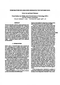
A scenario in the sense of Def. 21 is given by an ordered set of simulation steps together with a start state. In our simple example, the user interaction consists of triggering the next simulation step in case that there is a choice of actions in the current system state. Fig. 3 shows a scenario. The producer produces an item, delivers it to the buffer from where it is removed by a consumer, and, in the last step, consumed.
deliver
Consumer Producer
Buffer
Consumer
produce
produce
consume
remove
consume
Consumer
Fig. 4 Kitchen scenario view of the Producer-Consumer model Consumer Consumer Producer Producer
Buffer
Buffer
Consumer
Consumer Consumer Consumer
Item
Item
Consumer
remove deliver
Producer
Buffer
Item
Consumer
Consumer
Fig. 3 Scenario of the Producer-Consumer model, modeled as sequence of VL diagrams
4 2.2 Scenario Views To support an intuitive understanding of system behavior, especially for non-experts in the specific formal modeling language, it is desirable to have a visualization of (parts of) the VL model in the application domain and show the behavior directly in the layout of the application domain. Example 23 (Kitchen Scenario View) As an example, a scenario view for the Producer-Consumer model is considered for the concrete application domain of a kitchen: The producer is a cook and a consumer is some person eating (consuming) the cakes (items) which are produced by the cook and put onto a table (the buffer) in front of the consumer. Thus, the scenario in Fig. 3 can be presented in the kitchen scenario view as depicted in Fig. 4. Note that only one consumer is shown because the behavior of the consumer component in gen4 eral is interesting for the user validating the model. For a representation of a VL model’s behavior directly in an application-specific layout (e.g. the kitchen view), the graphical objects used in the VL model need to be mapped onto icons belonging to an applicationoriented kind of layout. The choice of representations suitable for the VL model objects depends on the nature
of a problem domain and its complexity, the preferences of users, the degree of their expertise in the problem domain, and on the modeling phase. In an early modeling phase, when the model is still on a very abstract level, a concrete visualization might have nothing to do with the real application domain of the model. For algorithm animation, there might not even be a real application domain (e.g. for modeling ”mutual exclusion”). But a realistic scenario from some easy-to-imagine real-world application domain (in the sense of a metaphor, where the literal meaning also is not the meaning intended) may help to get insights that are more difficult to get when looking at the formal model. Ideally, such a metaphor is used to communicate new concepts – the user recognizes anomalies between the existing knowledge (the formal model) and new information provided by the metaphor, and creates new knowledge by correcting the model to accommodate both sources (see [12]). This process can be improved if the user is given multiple metaphors, each correcting invalid extensions that might have been based on a single one. An example for two different metaphors for the Producer-Consumer model is given in Section 4 where the kitchen metaphor and the bottle machine metaphor are introduced as basis for scenario animation (cf. Fig. 10). In a later modeling phase, a visualization could even be on a higher abstraction level than the formal model itself. Consider for example a quite complex Petri net modeling a network protocol. We only want to know whether each host in the network is getting a message at some time and forwarding it. But the Petri net might contain so many places and transitions modeling the control conditions that we cannot immediately see whether the behavior is modeled correctly. In a visualization we would like to see only a graph of network nodes where an arc appears between two of them if a message is sent from one node to another. This could be done by defining visualizations only for the few marked places of the net which concern the sending of a message. In this case,
Scenario Animation for Visual Behavior Models: A Generic Approach
the visualization does not add a fictitious application domain but cuts out details that have to be present in the formal model but make it rather difficult to validate the behavioral requirements. Technically, we distinguish the representation of objects of a VL model from icons visualizing the context which can be thought of as the ’background’ or ’situation’ in which a VL model is interpreted. The context can be closely coupled with the overall behavior of the VL model under consideration and facilitates the users’ comprehension of this behavior.
5
views like the kitchen view can be defined and related such that the behavior is transferred from the model to the scenario view in a coherent way. For instance, we want to ensure that the behavioral constraint “Producers, Buffers and Consumers may hold at most one item at a time” is satisfied also in the kitchen view. Moreover, we sketch how the simulation steps in a scenario can be enhanced by more sophisticated animation features like e.g. continuous motion of objects. 3 The GenGED Approach
2.3 Animation in Scenario Views Another issue concerned with capturing the process of visualizing dynamic behavior, is the nature of animation. Graphics used in a scenario view can be defined to be either static or dynamic. Static graphics are still and unchanging (the context graphics). Dynamic graphics visualize some execution process undergoing successive changes by continuously modifying some of their attributes (e.g. they move or change their size or color). The definition of graphics for animation as building blocks for scenario views is a subjective activity which depends on the view designers’ creativity and imagination as well as their interpretation of what a VL model is for and how to convey the formal meaning through animation. Here, the nature of animation differs considerably from the notion of simulation as realized e.g. in GenGED. The Producer-Consumer scenario depicted in Fig. 3 is an example for a simulation run. Simulation visualizes state changes within the means of the VL model itself. The user who validates a model sees a graph, a statechart or a Petri net, where simulation steps are carried out by switching to another graph (as in Fig. 3), to another marking (as in a Petri net), or by highlighting another state (as in a statechart). Moreover, simulation relies on discrete steps and cannot depict changes continuously, e.g. the motion of an object. Animation visualizes the state changes in a scenario view which shows the model behavior using graphics from the application domain. Moreover, state changes can be depicted dynamically in the sense that the changes of graphical attributes (motion, change of size or color, ..) can be presented as continuous films. It is widely accepted that effective validation is performed when the users observe dynamic representation of the system’s requirements. Thus, in this paper, we advocate the integration of continuous animation in GenGED on top of the simulation features. It is very important that precision introduced by the VL model is carried over to the scenario view in the sense that the representation of a particular requirement should not deviate from or even contradict the actual meaning of the requirements as given by the VL model. In the next two sections we describe how VL models including VL diagrams like in Fig. 2 and scenario
GenGED (short for Generation of Graphical Environments for Design) [3,23] is based on the well-defined concepts of algebraic graph transformation [9]. The process for the validation of requirements using GenGED is carried out in two steps, the specification of a visual modeling language VL (described in Section 3.1), and the specification of a certain VL model (see Section 3.2). A VL model consists of a VL start diagram edited using the VL diagram editor generated from the VL specification, and a simulation specification. From the simulation specification, the VL simulation environment is generated allowing the user to interact visually with the VL model by generating scenarios in order to validate the VL model’s properties. The two-step workflow for using the GenGED environment is illustrated in Fig. 5. Alphabet Editor Grammar Editor
VL Specification VL Alphabet VL Syntax Grammar VL Diagram Editor
VL Model VL Diagram Simulation Rules
Simulation Component
Simulation Specification
VL Simulation Environment
Fig. 5 The GenGED environment
3.1 VL Specification A VL is defined by its VL alphabet describing the symbols of a VL and their spatial relations, and a set of editing rules limiting the number of meaningful models (VL syntax grammar). The VL alphabet together with the VL syntax grammar defines then the VL specification which is the basis for the generation of a VL-specific
6
Claudia Ermel, Roswitha Bardohl
graphical editor for diagrams corresponding to the specified VL. Definition 31 (VL Alphabet) A VL alphabet AV L = (T G, Csp) is given by a type graph T G and a constraint satisfaction problem Csp. – A type graph T G = (VS ∪ VA ∪ VG , ES ∪ EA ∪ EG ) is an attributed graph signature which can be represented as a graph whose nodes are sorts and edges are operations. The nodes in VS specify the symbol types of the language, the edges in ES : VS → VS link types, the nodes in VA attribute types (data types), and the edges in EA : VA → VS couple the attribute types with symbol types. The subgraph defined by (VS ∪ VA , ES ∪ EA ) comprises the abstract syntax of the VL alphabet. The concrete syntax (the graphics used for the layout of symbols and links) is represented by nodes in VG and edges in EG : VS → VG coupling the symbol types with their respective layout graphics in VG . – A graphical constraint satisfaction problem Csp which is a set of equations defining the spatial relations between different symbols by restricting the scope of constraint variables (denoting position and size of graphics). The Csp has to be solved by an adequate variable binding in each diagram over the VL alpha¤ bet (see e.g.[3]). VL diagrams are instances of a VL alphabet, e.g. graphs typed over the abstract syntax of the type graph. Conceptually, the layout for each symbol (the concrete syntax) is added to the abstract syntax by linking the symbol vertices to graphics. The Csp of the VL alphabet then is used to compute a concrete configuration of valid variable bindings for the positions and sizes of graphics. Definition 32 (VL Diagram) Let AV L be a VL alphabet according to Def. 31. Then, a VL diagram DV L is an attributed graph typed over the type graph T G of the VL alphabet. Additionally, the variable binding defining the layout configuration satisfies the Csp of the VL alphabet. ¤ Example 33 (VL Alphabet and Diagram) We consider the graph-like VL to visualize componentbased message-passing systems that was introduced informally in Section 2 (called Component VL from now on). Fig. 6 (a) shows a simplified kind1 of the VL alphabet for the Component VL. Symbol types are given by Component, Message, MessAssoc (Message Associations) and Channel shown in the abstract syntax graph in the upper part of Fig. 6 (a). The edges labeled s and t denote the source and target relations of channels. Attribute types are depicted as rounded rectangles and contain the String datatype for component names (CName) and message texts (MName). 1
In this article we do not concentrate on the definition of graphics and Csps which is comprehensively described in [2].
s Component
Channel t
MessAssoc CName
Message MText
String
String
2:Channel
1:Channel s 1:Component
CName Producer
t
s
2:Component 1:MessAssoc
t 3:Component CName
CName
Buffer 2:Message
Consumer MText Item
CName Producer MText
Buffer
Consumer
Item (a)
(b)
Fig. 6 (a) VL alphabet of the component VL and (b) VL diagram typed over the VL alphabet
In the lower part of Fig. 6 (a) we see the respective symbol type layout (the concrete syntax): components are drawn as boxes with their names inside, messages are cylindric containers containing text (e.g. address, sender, content,...), channels are thick lines connecting two components, and message associations are arcs connecting a message and the component which is keeping the message currently. The Csp (not shown in Fig. 6 (a)) makes sure, e.g., that message containers are always depicted below component boxes, and that the channels between components touch the borderlines of the boxes. One VL diagram according to this alphabet showing a state of a Producer-Consumer model, is illustrated in Fig. 6 (b). Here, in the upper part of the figure, the nodes are instances of the respective symbol types in the type graph. Note that we abstract from the notion of Message: a message can be anything to be passed between components, not just text. 4 Sometimes two different kinds of diagrams are logically related, e.g., class diagrams and statecharts. In this case, a VL specified in GenGED would comprise a combination of both kinds of diagrams. A concrete diagram (e.g. a statechart) then can be seen as one view on the complete model. See [6] for the definition of such a combined VL for a two-level architecture design language consisting of a network level (a graph) and a specification level where each graph node is refined by a behavior specification (a Petri net). The editing of a VL diagram is realized by applying syntax grammar rules (covering the insertion and deletion of symbols as well as the modification of symbol attributes) to the respective VL diagram in the generated visual editor. In addition to syntax directed editing, GenGED supports free-hand editing based on a parse grammar [8]. For rule applications, the graph transformation engine Agg [22,1] is used. The VL syntax grammar restricts the set of VL diagrams comprising the VL to the meaningful ones. Definition 34 (VL Grammar) Let AV L be a VL alphabet according to Def. 31. A VL
Scenario Animation for Visual Behavior Models: A Generic Approach
grammar GGV L = (SV L , RulesV L ) w.r.t. AV L consists of – a start diagram SV L , a VL diagram w.r.t. AV L according to Def. 32, – a set of rules RulesV L where each rule r ∈ RulesV L consists of a left-hand side L and a right-hand side R which are VL diagrams, a rule morphism L−→ ◦ R which is a partial attributed graph morphism on the abstract syntax level, and (optionally) some negative ¤ application conditions. Definition 35 (VL Specification, VL) The visual language V L which is described by the visual language specification SpecV L = (AV L , GGV L ) with GGV L = (SV L , RulesV L )) is given by all VL diagrams DV L derivable from the start diagram SV L with the VL rules in RulesV L : ∗
7
Example 37 (Simulation Grammar) A part of the simulation grammar for our ProducerConsumer model is shown in Fig.7. The complete simulation grammar consists of four rules corresponding to the possible actions produce, deliver, remove and consume.
L / NAC
CName
MessAssoc
Producer
Message
∗
¤ ∗ One derivation sequence SV LM =⇒Rulessimu DV L of a VL model corresponds to a scenario. The choice of rules and rule matches and the resulting rule applications leading to such a scenario is called simulation of a VL model. Using the GenGED simulation component, simulation rules may also be grouped to simulation expressions by various control structures such as loops, sequential composition of rules and conditional rule applications. The set of simulation expressions together with the start diagram defines the simulation specification. In order to keep the examples simple, we restrict ourselves to simulation grammars here and do not regard more complex simulation specifications. Thus, a simulation specification corresponds to a simulation grammar in this paper.
Producer
Message MText
Producer Item R
2:Component 1:Component CName
CName Buffer
1:Channel
Producer
1:MessAssoc
MText
1:Message
Item
Item
V LM = {DV L |SV LM =⇒Rulessimu DV L }
MessAssoc
Item
MText
Definition 36 (VL Model) A VL model V LM is a sublanguage of VL defined by the VL specification SpecV LM = (AV L , GGsimu ), where GGsimu = (SV L , Rulessimu )) is a simulation grammar. For each simulation rule r ∈ Rulessimu , the left-hand side L contains the subpart of the state relevant for the state transition to be considered. In the right-hand side R, the update of this subpart is modeled after the state transition has been performed.
MText
L / NAC
¤
The behavior of a VL model is specified by VL rules called simulation rules which represent transitions between system states. All VL diagrams that can be generated by applying simulation rules beginning from the start diagram comprise the VL model. Technically, a VL model is a sublanguage of the visual modeling language VL.
CName
Item
Producer
Message
3.2 Simulation Specification
1:Component
produce
Item
MessAssoc
V L = {DV L |SV L =⇒RulesV L DV L }
R
1:Component
Producer Item
2:Component 1:Component CName deliver Producer MText Item
Buffer Item
Producer
CName Buffer
1:Channel 2:MessAssoc 2:Message Buffer Item
Fig. 7 Simulation grammar for the Producer-Consumer model
The rules remove and consume are not shown in Fig. 7 as they are constructed analogously. Rule morphisms from the left-hand side L to the right-hand side R are indicated by numbers. A negative application condition (NAC) specifies a situation which must not occur for the rule to be applied and is indicated by dashed boxes in the abstract syntax of the left-hand sides of the rules and by crossed-out objects at the concrete syntax level. The NACs model the system constraint that a component may hold at most one message. The layout (the concrete syntax) of the symbols and links in the rule graphs (L, R and the NAC) is computed automatically as a solution of the Csp defined for the VL alphabet. To apply a simulation rule to a diagram of our VL model (the graph depicted in Fig. 6 (b)), we have to find a mapping from the objects (nodes and edges) in L to the objects in the graph. Moreover, the NAC of the rule must not be present in the graph. Only one rule from our simulation grammar is applicable to the state in Fig. 6 (b), namely rule remove. The application of a rule to a graph resulting in a graph modified according to the rule is called a derivation. In the case of our simulation grammar, the derivations are called simulation steps because the rules model the transitions from one system state to another. Fig. 8 illustrates a simulation step. The rule remove is applied to graph G resulting in graph H. 4
8
Claudia Ermel, Roswitha Bardohl L / NAC
2:Component MessAssoc
1:Component
Buffer
1:MessAssoc
MText
MText
1:Message
Item
Item
Buffer
R
2:Component 1:Component
2:Channel
CName
Message
CName Consumer
Buffer
2:MessAssoc
MText 2:Message
Item Consumer
Item
2:Channel
CName remove
Buffer
Consumer
Item
G
CName Consumer
Item H
2:Channel
1:Channel 1:Comp. CName Producer
Producer
2:Comp. 1:MessAssoc 1:Message
Buffer Item
1:Channel
3:Comp. CName
1:Comp. CName CName
Buffer MText Cons. Item Consumer
Producer Producer
2:Channel
2:Comp. 2:MessAssoc 2:Message
Buffer
3:Comp. CName
CName
Buffer Cons. MText Item Consumer Item
Fig. 8 A simulation step for the Producer-Consumer model
3.3 Generation of Simulation Grammars for arbitrary VL Models In Section 3.2, we simply defined the simulation grammar with respect to our producer-consumer model and thus gave our VL model an operational semantics. Usually, it is desirable to consider more than one VL model for a specific VL (such as Petri nets, for instance). Then the specification of the respective simulation grammar for each different net by the user is not feasible. Rather, the operational semantics should be fixed once for a specific VL and cover all VL models. There are essentially two ways to define operational semantics for behavioral models by graph transformations [10]. In the first approach, graph transformation rules specify an abstract interpreter for the entire language as proposed, for example, in [5] for a simple version of statecharts. Such an interpreter is valid for the whole language and can be applied to all valid diagrams. This first approach has been followed in the GenGED environment (see Fig. 5) up to now, where the simulation grammar is edited by the language designer using the grammar editor. The disadvantage is that such an abstract interpreter is not a good basis for animation since animation is highly dependent on a specific model. As a second approach to operational semantics, each model can be “compiled” into a set of rules. Roughly, models are translated to simulation rules by a “compiler”, for example yet another graph grammar. The resulting set of simulation rules is specific to a particular model. Note that if such a compiler is specified as graph grammar, the right-hand side of a compiler rule contains a complete rule2 . This second “compilative” approach is followed in this paper because the generated model-specific simulation rules provide a good basis for animation. We describe a “compiler” grammar for our Component VL which generates for each VL diagram 2
Technically, this generated rule is represented as graph.
over the Component alphabet a corresponding simulation grammar (and thus establishes a VL model). Applied to our producer-consumer diagram in Fig. 6 (b), the compiler grammar generates the set of simulation rules introduced in Section 3.2. Compiler rules can be generally specified as follows: We distinguish between static and dynamic symbol types in a VL. Static symbols do not change (they comprise the context of a VL model), and dynamic symbols change during simulation. In our Component VL, for instance, components and channels are static symbols whereas messages are dynamic. Each left-hand side of a compiler rule contains the static symbols which are part of an action (a transition between two system states of a VL model). The corresponding right-hand side contains a simulation rule covering the respective transition from one system state to the next, containing the static symbols from the left-hand side plus dynamic symbols which are deleted or generated by the simulation rule. Fig. 9 illustrates the abstract syntax of the compiler rules for our Component VL. L / NAC
R
Component 1:Component s t Channel
L / NAC
R
1:Component
gen_ newMsg(String)
1:Component newMsg (String)
MessAssoc
MessAssoc MText Message
L / NAC
R
Component Component s t Channel
(String)
L
Message
R 1:Component
gen_ delMsg(String)
1:Component delMsg (String)
MessAssoc MText (String)
R
L 2:Component 1:Component t s Channel
gen_ mvMsg(String)
Message
L / NAC 2:Component t 1:Component s Channel MessAssoc
MessAssoc
mvMsg (String)
1:Component s t 2:Component Channel
MessAssoc
MText
MText (String) Message
R
Message
(String)
Message
Fig. 9 Compiler rules to generate simulation grammars from VL diagrams over the Component alphabet
For each different action type in a conceivable VL model (generate a new message, move the message along a channel to a right neighbour component, delete a message), there is one rule in the compiler grammar. For the generation and deletion of messages, only single component symbols are concerned. Hence, the first two rules require one component symbol in their respective lefthand sides. The NACs ensure that the component allowed to generate a message is one of the first in the communication chain (e.g. it has no left neighbours, like the producer in Fig. 2) and, analogously, the component allowed to delete a message is one of the last in the chain (e.g. it has no right neighbours, like one of the three consumers in Fig. 2). For the movement of messages along a channel, we have to consider two components with a
Scenario Animation for Visual Behavior Models: A Generic Approach
channel between them. Each compiler rule has to be applied exactly once at each possible match. As an example we consider the generation of the simulation grammar for the Producer-Consumer model partly depicted in Fig. 7. These simulation rules are generated by applying the compiler rules from Fig. 9 to the Producer-Consumer diagram from Fig. 6 (b): The first simulation rule produce is generated by applying the compiler rule gen newM sg(String) in a way that the “1:Component” node from the left-hand side of the compiler rule is mapped to the “1:Component” node in the diagram. The string variable (the message text) is mapped to “Item”. According to the right-hand side of the compiler rule, the simulation rule produce is the result of the compiler rule application. The other simulation rules are generated analogously.
4 Generation of Scenario Views in GenGED In this section, we explain how scenario views are defined by an extension of the VL alphabet defined so far (called Kernel Alphabet from now on). The extension embeds new symbol types that are visualized in a new layout but are connected to the old symbol types of the kernel alphabet to allow a coherent translation from all diagrams in the old layout to the scenario view. As sketched in Section 2, our aim is the integration of animation operations (such as continuous motion of graphics) with the simulation features in GenGED in a way that the behavior of the VL model is carried over consistently to the scenario view. Therefore, it is necessary to scrutinize the relationship between a VL model and its corresponding visualization to avoid the development of ad-hoc visualizations that are not related to the model. Instead, scenario views should be developed systematically and be driven by the underlying behavior (formalized as simulation grammar in GenGED) for which the visualization is used. Hence, our approach is based on a formal view transformation graph grammar which is used not only to transform the underlying VL model to its new layout in the scenario view, but also to map the simulation rules to animation rules in the scenario view. These animation rules are modeled by grammar rules which are enhanced by operations for continuous changes of objects such as motions or changes of size or color. Note that in our approach the original formal model is not changed since the visualization process takes place after the formal specification of the model.
4.1 Extending the Kernel Alphabet to a View Alphabet Let us consider two sample scenario views for our abstract Producer-Consumer model for two different application domains:
9
– the kitchen view (presented already in Section 2), where the producer is a cook and the consumer is some person eating the cakes (items) which are produced by the cook and put onto a table (the buffer), – and a bottle machine view, where people can return empty bottles with refundable deposit. The machine (the buffer) accepts an empty bottle (the item ) from a person (the producer). Then the bottle is transported via a conveyor belt to a box (the consumer). The bottle falls into the box (it is consumed). Fig. 10 shows a state of a Producer-Consumer model (for simplicity we have only one consumer here), its abstract syntax and two snapshots of this state according to the two different application domains kitchen and bottle machine. Note that the channels specified in the formal model are not depicted in the first scenario view but one channel namely that one between the buffer and the consumer has a visualization as conveyor belt in the second scenario view such that the two views are not isomorphic but structurally different. Abstract Syntax 1:Channel
1:Component
2:Channel
2:Component
3:Component CName
CName
CName 1:MessAssoc
Producer
Buffer 2:Message
Consumer MText
Item
Producer
Buffer
Consumer
Item
Formal Model
Scenario View 2
Scenario View 1
Fig. 10 Two scenario view snapshots of a state of the Producer-Consumer model
On a first glance, it seems that for both the VL model and its two views, the abstract syntax remains the same and only the layout for the symbols is different. But, as in the GenGED approach symbol types are connected with symbol graphics, we cannot simply exchange the concrete syntax levels. Consider, for example, the layout for component nodes: In the formal model, each component symbol is drawn as a box. In the kitchen scenario view, a component may be either visualized as a cook (if it is named “Producer” in the formal model), or as a table (if it is the buffer) or as a person sitting on a chair (if its meaning is “Consumer”). The visualization depends
10
Claudia Ermel, Roswitha Bardohl
not only on the symbol type in the abstract syntax of the formal model, but also on the textual attributes which carry the meaning of each symbol in a VL model. Thus, for the definition of a new scenario view, we have to find a way to extend the kernel alphabet by model-specific symbols which are visualized differently in the scenario view. We call the extended alphabet View Alphabet. Again, we use the notions dynamic and static symbols for symbols that are deleted or generated in some simulation rule (dynamic symbols) and symbols that are preserved by all simulation rules, e.g. that comprise the context (static symbols). The corresponding symbol types in the alphabet are called dynamic or static symbol types. Definition 41 (View Alphabet) For a given kernel alphabet with a set of symbol and link types and a given VL model consisting of a VL diagram and a set of simulation rules over this kernel alphabet, a view alphabet is constructed as follows: 1. The initial view alphabet is the kernel alphabet. 2. (Static symbols) For each static symbol A in the VL diagram a new symbol type node is added to the view alphabet. The new symbol type node is connected to the original symbol’s type node of the kernel alphabet and is attributed by the new layout graphic for the scenario view. Formally, the new node represents a subtype of the original symbol type, so we call the new symbol type node subtype and its connection to the original symbol type a subtype link. For each link in the VL diagram between the static symbol A and a static symbol B, sublinks are inserted in the view alphabet between the corresponding subtypes. 3. (Dynamic symbols) If there exists a link between a static symbol type S and a dynamic symbol type D in the kernel alphabet, then for each of the static subtypes of S in the view alphabet, a dynamic subtype of D is generated, linked to the static subtype and (by subtype link) to its dynamic symbol type D in the kernel alphabet. The new dynamic subtype of D is attributed by the new layout graphic for the scenario view. 4. (Layout Constraints) A new constraint satisfaction problem defining layout restrictions is specified for the links between the subtypes according to their spatial relations. ¤ Note that the original kernel alphabet is not changed by the construction of a view alphabet; even the original layout of the old symbol types is still available. Attributes are not always needed in the model-specific part of the view alphabet since attributes usually describe some semantic notion of a symbol. In the scenario view, this notion might be already captured by the visualization of the corresponding subtype symbol. If they are
needed (e.g., for graphical constraint computation), the attributes are simply copied to all subtypes of the attributed symbol type. Example 42 (Kitchen View Alphabet) An example for a view alphabet is given by Fig. 11 showing the view alphabet for the kitchen view of the Producer-Consumer model. For the static symbol type Component we constructed the subtypes C-Producer, CBuffer and C-Consumer. For the static symbol type Channel, the subtypes Ch-Producer-Buffer and Ch-Buffer-Consumer are constructed. The sublinks from the Channel-subtypes to the Component-subtypes are added according to the Producer-Consumer diagram in Fig. 6 (b). For the dynamic symbol types Message and MessAssoc, subtypes are created for all Component subtypes. All subtypes are linked to the corresponding supertypes in the kernel alphabet and to their scenario view layout graphics (as indicated by the dashed lines in Fig. 11). The layout of the view alphabet subtypes (formally defined by a Csp, not shown here) is indicated by the spatial relations between the layout graphics. The new Csp constraints ensure that the respective icons are positioned adequately, e.g. that the cake is depicted on top of the stove or on top of the table depending on the respective component subtype the message is associated to. Kernel Alphabet
CName Channel
Component
MessAssoc
Ch-Producer-Buffer C-Producer MA-Producer M-Producer
MText Message
Ch-Buffer-Consumer
C-Buffer MA-Buffer M-Buffer
C-Consumer MA-Consumer M-Consumer
Fig. 11 View alphabet for the kitchen view of the ProducerConsumer model
4 4.2 Translating the VL Model according to a View Alphabet Now we extend in a systematic way the abstract syntax of our VL model such that it fits to the view alphabet: We define a view transformation based on the view alphabet. The view transformation is formalized as graph grammar whose rules are applied on the one hand to the VL diagram representing the start state of our VL model, and on the other hand to the VL model’s simulation rules. Fig. 12 shows the abstract syntax of the view transformation rules for the kitchen view of our
Scenario Animation for Visual Behavior Models: A Generic Approach Rules for Components: (cons not depicted)
L / NAC
Component
R
CName
C-Producer
Producer
R
Component C-Producer
Component
L / NAC
Component
Component C-Producer
C-Buffer
MessAssoc
Component
C-Buffer
Component
Component
C-Buffer
C-Consumer
C-Buffer MA-Buffer
Channel Component
Component
C-Buffer
C-Consumer
ch_B_C
C-Buffer
Ch-Buffer-Consumer
Ch-Buffer-Consumer
Ch-Producer-Buffer
R
MessAssoc
Component
Buffer
C-Buffer
Channel Component
CName
Component
buff
R
L / NAC
L / NAC
MessAssoc
R
Component
m-buff Message
R
CName Buffer
ch_P_B
Ch-Producer-Buffer
L / NAC
Producer
Channel
Channel
Rules for Messages: (m-prod not depicted):
CName
C-Producer
prod
L / NAC
Rules for Channels:
Component
11
MessAssoc
Component
m-cons Message M-Buffer
C-Buffer
Message
MA-Buffer
Message
C-Consumer
C-Consumer
M-Consumer
MA-Consumer
MA-Consumer
Fig. 12 View Transformation grammar for the kitchen view of the Producer-Consumer model
Producer-Consumer model. View transformation rules extend the abstract syntax of a VL diagram by symbols typed over the new subtypes in the view alphabet. The new layout of a VL diagram whose abstract syntax has been extended by view transformation is fixed already by the concrete syntax for the new symbols as defined in the view alphabet. The construction of the view transformation rules is quite straightforward: Depending on its kernel symbol type and its textual attribute, each symbol is extended by a corresponding subtype symbol, and each link between two symbols by a sublink between the corresponding subtype symbols. We have two rules for each of the three component subtypes in our view alphabet: one rule adds the specific component subtype node, the other treats the case that the component holds a message: in this case a specific message subtype node is created and associated to the component. Two other rules add the channel subtype nodes and links. The view transformation grammar is used to transform a VL model to a scenario view layout in two steps: Firstly, the start diagram of the VL model is transformed by applying the view transformation rules to it as long as the rules are applicable. Secondly, the simulation rules (see Fig. 7) are transformed into the scenario view layout as well by applying the view transformation rules to the left-hand side and to the right-hand side of each simulation rule. A view transformation applied to the simulation rule deliver is shown in Fig. 13. Instances of the subtype symbols (and, implicitly, their new layout) are added to each rule side. Note that the original layout of instances according to the kernel alphabet is not lost by the view transformation but only left out in Fig. 13. 4.3 Animation of Scenarios in the Scenario View The implementation of the concepts presented so far in the GenGED environment is work in progress. An animation editor allows to enrich the transformed simu-
L / NAC
R Producer
Buffer
Item
2:Component
1:Component
CName Buffer
1:Channel
1:MessAssoc
MessAssoc
MText 1:Message
Message
Item
View Transformation of R
View Transformation of L / NAC R 2:Component
1:Component
Producer
Buffer
MText
Message
Item C-Buffer
MA-Producer
Ch-Producer-Buffer M-Buffer
Message
Item
MA-Buffer Ch-Producer-Buffer
MessAssoc
1:Message
C-Producer
Buffer
1:Channel
MText
deliver
CName
2:Component
1:Component
1:MessAssoc
MessAssoc
1:Message
C-Producer
CName
CName
1:Channel
1:MessAssoc
M-Producer
2:Component
1:Component
Message
Item
CName Producer
Buffer
Producer
deliver
MessAssoc
MText
L / NAC
CName
CName
1:Channel
1:MessAssoc
1:Message
Item
Item
CName Producer
Buffer
Producer
C-Buffer
MA-Buffer M-Buffer
Fig. 13 A simulation rule transformed into the layout for the kitchen scenario view
lation rules for the scenario views by animation operations realizing continuous changes of graphics such as moving, appearing or disappearing, growing or shrinking or changing the color. The view designer defines these animation operations visually, e.g. by drawing a required on-screen route interactively on the scenario background. Moreover, more than one animation operation can be defined for one rule: a time-line diagram at the bottom of the screen in Fig. 14 shows the starting time and duration for each animation operation and allows the view designer to change them. Animation operations are executed during rule application, such that not only discrete steps from one system state to another are shown but rather a continuously animated change of the scene. Scenario animation then comprises the application of these enriched simulation rules (called animation rules) in the layout of the scenario view to states of
12
the VL model. Fig. 14 shows the animation editor where the upper part depicts the animation rule. In the lower part, the time line for the synchronization of starting and ending times for animation operations is shown. In our example, one linear-move operation starts half a second after the beginning of the animation step and lasts 3 seconds. The second linear-move operation starts while the first operation is still running and ends after 5 seconds, i.e. it takes longer than the first motion.
Claudia Ermel, Roswitha Bardohl
presents the GenGED environment (whose basic features were depicted in Fig. 5) now extended by the scenario view methodology proposed in this paper. Alphabet Editor
(1)
(1) Grammar Editor
VL Specification VL Kernel Alphabet VL Syntax Grammar VL Diagram Editor
(2)
(3)
VL Model
(1) Compiler
(2)
(2)
(3)
(3)
VL Diagram Simulation Rules (3)
View Transformation (3)
(4) Animation Editor (4) VL Simulation and Animation Environment
View Alphabet VL Kernel Alphabet + model specific subtypes and their layout
VL Model in Scenario View VL Diagram and Simulation Rules in the layout of an application domain Animation Grammar (5)
Animation Specification in SVG
Fig. 15 The GenGED environment extended by features for scenario view definition and animation
Fig. 14 The animation editor in the extended GenGED environment
Single animation steps can be viewed in the animation environment by applying an animation rule to a VL diagram. Animation sequences can be recorded by performing a sequence of animation rule applications. The complete animation specification then is stored in the XML-based SVG format (Scalable Vector Graphics [34]) and can be viewed by any external SVG viewer tool. In a conceivable GenGED user interface for handling different views, the formal model should be shown in the layout of the kernel alphabet in one window, the scenario views (one or more at a time) in other windows. The triggering of the simulation or animation steps (by selecting a rule) is visualized in all scenario views (and the formal model itself) at once. If there is a structural change in the formal model (such as adding a component), then the generation of adequate scenario views has to be repeated, i.e. if the view alphabet is changed by the view designer, the view transformation grammars must be re-generated. 4.4 Summary: The Complete Methodology in GenGED Summarizing, we presented a methodology enriching the GenGED environment by means to define scenario views and their animation in a generic way. Our approach is heavily based on graph grammars which allow flexible model transformations for various purposes. Fig. 15
We explain Fig. 15 by adding to the workflow different roles for users of the GenGED environment (different roles need not necessarily be taken by different persons) and describing who is doing what: (1) The language designer defines the VL Specification by using the Alphabet Editor to define the VL Kernel Alphabet and using the Grammar Editor to define the VL Syntax Grammar. Additionally (if the VL is a visual behavior modeling language), he defines the operational semantics (the Compiler) in terms of a compiler grammar using again the Grammar Editor. (2) The model designer uses the VL Specification to edit a VL diagram and evokes the Compiler to generate Simulation Rules from his VL Diagram. Alternatively, the Simulation Rules can be defined “by hand” using the Grammar Editor. The VL Diagram together with the Simulation Rules specifify the VL Model. (3) The view designer specifies a Scenario View by defining the View Alphabet (extending the VL Kernel Alphabet by subtypes according to the VL Model). Additionally, he defines the View Transformation Grammar over the view alphabet. Applying the View Transformation Grammar to the VL Model, he generates a transformed VL Model in the Scenario View. (4) The animation designer uses the Animation Editor to enhance the transformed simulation rules for the scenario view by animation operations and thus constructs Animation Rules for the scenario view. (5) the model validator works in the VL Simulation and Animation environment by loading a VL Model (either in the original layout or in the layout of a scenario view) and simulating (or animating) its behavior by
Scenario Animation for Visual Behavior Models: A Generic Approach
applying the rules of the corresponding simulation (or animation) grammar. He can also generate animation sequences and export them to the SVG format, to be viewed by an external SVG viewer tool.
5 Conclusion and Future Work We have reasoned about the benefits of a visual environment for the employment of visual modeling techniques by discussing the GenGED approach. In general, existing tools supporting visual modeling are restricted to a fixed visual modeling language. The advantage of the GenGED approach is to support the generation of a small application specific visual modeling environment including the systematic derivation of scenario views in the layout of an arbitrary application domain. This is done by means of a formal view transformation grammar, where the resulting animation rules are enhanced by animation operations for, e.g., continuous motion of icons. The definition of the operational semantics for visual models can be abstractly described by a grammar generator (compiler). A model designer may use these compilers without being aware of the theoretical background of their abstract specification. In order to learn more about the practicability and feasibility of this approach, more complex case studies (VLs and scenario views) have to be examined as future work. Due to the generic and modular definition of syntax, behavior and animation for formal visual models, the presented framework reduces considerably the amount of work to realize a domain-specific animation of a system’s behavior. Yet, it would be even more desirable to have an interconnection between GenGED and other tools supporting the definition of VL models, e.g. the large world of Petri net or UML tools. The motives for such a tool interconnection are obvious: Petri net tools which are focussed on formal analysis of their models could profit from the scenario view support offered by GenGED, whereas GenGED might export a Petri net to a Petri net tool for formal analysis. Within the Petri Net Baukasten [19] of the Petri Net Researcher Group, the presented scenario animation framework of GenGED is planned to become an extension of the functionality provided by the Petri net tool environment Petri Net Kernel (PNK) [27] and by the external tools integrated over the PNK. In order to offer the features of GenGED to PNK users, an XML conversion between the XML file formats of the PNK and GenGED has been implemented [21]. Up to now, place/transition nets edited with the PNK can be converted to the GenGED format and vice versa. Work is in progress to support the conversion of other Petri net classes as well. An exchange then can take place for nets belonging to net classes which are known both to GenGED (suitable grammars for syntax and operational semantics exist) and to the PNK (a specification of the
13
Petri net class and its firing rule exists). Thus, the generation of scenario views in GenGED becomes possible for Petri nets which have been edited by the PNK or imported from other tools to the PNK. A more open tool interconnection is a modular approach where the formal model defined elsewhere is not converted into the GenGED format and then imported by GenGED, but where the tool wanting to perform an animation, triggers animation steps by messages to GenGED encoding rule applications for a specific scenario view. This requires a library of scenario views (animation modules) in GenGED and the ability to process remote method invocation (as implemented e.g. by Java-RMI). An application for such a modular use of scenario views is described in [7]. Here, the integration of the tools Platus, designed to construct visual behavior models and analyze their performance, and GenGED for defining animation modules is discussed. Future work will be done to enhance the GenGED environment in order to model and check scenario views and to offer animation features to other tools via an interface for remote method invocation. As views play an important role not only for animation, we will consider the abstraction of our methodology to allow more general aspect-oriented views such as the combination of various diagram languages in UML [31]. Adequate case studies using different visual modeling techniques will be investigated to validate the usefulness of our approach towards a rapid prototyping environment for visual modeling, simulation and animation. Acknowledgements We would like to thank the anonymous reviewers for their valuable and constructive suggestions on previous drafts of this paper.
References 1. AGG Homepage. http://tfs.cs.tu-berlin.de/agg. 2. R. Bardohl. GenGEd – Visual Definition of Visual Languages based on Algebraic Graph Transformation. Verlag Dr. Kovac, 2000. PhD thesis, Technical University of Berlin, Dept. of Computer Science, 1999. 3. R. Bardohl. A Visual Environment for Visual Languages. Science of Computer Programming (SCP), 44(2):181– 203, 2002. 4. R. Bardohl, K. Ehrig, C. Ermel, A. Qemali, and I. Weinhold. GenGEd – Specifying Visual Environments based on Visual Languages. In H.-J. Kreowski, editor, Proc. of APPLIGRAPH Workshop on Applied Graph Transformation (AGT 2002), pages 71–82, 2002. 5. R. Bardohl and C. Ermel. Visual Specification and Parsing of a Statechart Variant using GenGEd. In Statechart Modeling Contest at IEEE Symposium on Visual Languages and Formal Methods (VLFM’01), pages 3–5, Stresa, Italy, September 5–7 2001. http://www2. informatik.uni-erlangen.de/VLFM01/Statecharts/.
14 6. R. Bardohl, C. Ermel, and J. Padberg. Transforming Specification Architectures by GenGED. In [14], pages 30–44. 7. R. Bardohl, C. Ermel, and L. Ribeiro. A Modular Approch to Animation of Simulation Models. In Proc. 14th Brazilian Symposium on Software Engineering, pages 498–520, Joao Pessoa, Brazil, October 2000. 8. R. Bardohl, T. Schultzke, and G. Taentzer. Visual Language Parsing in GenGEd. In Proc. of Satellite Workshops of 28th Int. Colloqium on Automata, Languages, and Programming (ICALP’2000), pages 291–296. Elsevier, July 2001. See also ENTCS series at http://www. elsevier.com/locate/entcs/volume50.html, issue 3. 9. R. Bardohl, G. Taentzer, M. Minas, and A. Sch¨ urr. Application of Graph Transformation to Visual Languages. In [15], pages 105–181. 10. L. Baresi and R. Heckel. Tutorial Introduction to Graph Transformation: A Software Engineering Perspective. In [14], pages 402–202. 11. L. Baresi and M. Pezze. A Toolbox for Automating Visual Software Engineering. In R. Kutsche and H. Weber, editors, Proc. Fundamental Approaches to Software Engineering (FASE’02), Grenoble, April 2002, pages 189 – 202. Springer LNCS 2306, 2002. 12. A. F. Black. Metaphor in Diagrams. PhD thesis, Darwin College, Cambridge, Massachusetts, 1998. 13. J. M. Carroll, editor. Scenario-Based Design. John Wiley & Sons, New York, 1995. 14. A. Corradini, H. Ehrig, H.-J. Kreowski, and G. Rozenberg, editors. Proc. First Int. Conference on Graph Transformation (ICGT’02). Springer LNCS 2505, 2002. 15. H. Ehrig, G. Engels, H.-J. Kreowski, and G. Rozenberg, editors. Handbook of Graph Grammars and Computing by Graph Transformation, Volume 2: Applications, Languages and Tools. World Scientific, 1999. 16. Honeywell Technology Center. DOME Guide, Version 5.2.1, 1999. http://www.thc.honeywell.com/dome/. 17. J. de Lara and H. Vangheluwe. ATOM3 : A Tool for Multi-Formalism Modelling and Meta-Modelling. In R. Kutsche and H. Weber, editors, Proc. Fundamental Approaches to Software Engineering (FASE’02), Grenoble, April 2002, pages 174 – 188. Springer LNCS 2306, 2002. 18. D.F. D’Souza and A.C. Wills. Objects, Components, and Frameworks With UML: The Catalysis Approach. Addison-Wesley Object Technology Series. Addison-Wesley, 1998. See also http://www.catalysis.org/books/ocf/index.htm. 19. H. Ehrig, W. Reisig, and H. Weber et al. The Petri Net Baukasten of the DFG-Forschergruppe PETRI NET TECHNOLOGY. In Ehrig et al. [20]. 20. H. Ehrig, W. Reisig, G. Rozenberg, and H. Weber, editors. Advances in Petri Nets: Petri Net Technology for Communication Based Systems. LNCS 2472. Springer, 2003. To appear. 21. C. Ermel, R. Bardohl, and H. Ehrig. Specification and Implementation of Animation Views for Petri Nets. In Weber et al. [32], pages 75–92. 22. C. Ermel, M. Rudolf, and G. Taentzer. The AGGApproach: Language and Tool Environment. In [15], pages 551–603. 23. GenGED Homepage. http://tfs.cs.tu-berlin.de/genged.
Claudia Ermel, Roswitha Bardohl 24. M. Glinz. Improving the Quality of Requirements with Scenarios. In Proc. of the Second World Congress for Software Quality (2WCSQ), Yokohama, pages 55 – 60, September 2000. 25. Bernd Grahlmann. The State of PEP. In M. Haeberer A. editor, Proceedings of AMAST’98 (Algebraic Methodology and Software Technology), volume 1548 of Lecture Notes in Computer Science. Springer-Verlag, January 1999. 26. D. Harel. From Play-In Scenarios to Code: An Achievable Dream. IEEE Computer, 34(1):53–60, january 2001. 27. E. Kindler and M. Weber. The Petri Net Kernel Documentation of the Application Interface, Revision 2.0, http:// www.informatik.hu-berlin.de/ top/ pnk/ index. html. Forschergruppe Petrinetz-Technologie an der Humboldt-Universit¨ at zu Berlin, Januar 1999. 28. MetaCASE KOGGE - KOblenz Generator for Graphical Environments. http://www.uni-koblenz.de/ist/kogge.en. html. 29. O. K¨ oth and M. Minas. Generating Diagram Editors Providing Free-Hand Editing as well as SyntaxDirected Editing. In H. Ehrig and G. Taentzer, editors, Proc. GRATRA’2000 - Joint APPLIGRAPH and GETGRATS Workshop on Graph Transformation Systems, pages 32–39. Technische Universit¨ at Berlin, March 25-27 2000. 30. A. Sch¨ urr, A. Winter, and A. Z¨ undorf. The PROGRESApproach: Language and Environment. In [15], pages 487–550. 31. Unified Modeling Language – version 1.3, 2000. Available at http://www.omg.org/uml. 32. H. Weber, H. Ehrig, and W. Reisig, editors. 2nd Int. Colloquium on Petri Net Technologies for Modelling Communication Based Systems, Berlin, Germany, Sept. 2001. Researcher Group Petri Net Technology, Fraunhofer Gesellschaft ISST. 33. K. Weidenhaupt, K. Pohl, M. Jarke, and P. Haumer. Scenarios in System Development: Current Practice. IEEE Software, 15(2):34 – 35, Mar/April 1998. 34. WWW Consortium (W3C). Scalable Vector Graphics (SVG) 1.0 Specification. http:// www.w3.org/ TR/ svg , 2000. 35. K. Zhang, D. Zhang, and J. Cao. Design, Construction and Application of a Generic Visual Language Generation Environment. IEEE Transactions on Software Engineering, 27(4):289–307, 2001.
Scenario Animation for Visual Behavior Models: A Generic Approach
Claudia Ermel received the B. Eng. degree in informatics from the University of Applied Sciences (TFH), Berlin, Germany, in 1989, and the Masters degree in computer science from the Technical University of Berlin, Germany, in 1996. She joined the Institute of Software Technology and Theoretical Computer Science at the Technical University of Berlin in 1989. Her current research interests include Petri nets and other visual modeling techniques, and the graph-grammar-based generation of modeling and simulation tools from formal visual language specifications. – Member of the GI (German Assosiation of Computer Scientists) since 1988 – Co-organizer of ETAPS 2000, GraTra 2000, UniGra 2001, UniGra 2003 – Guest editor of the proceedings UniGra 2001
15
Roswitha Bardohl received her Diploma in Computer Science from the Technical University of Berlin (TUB), Germany, in 1993 and her doctoral degree in 1999. She is employed at the Institute of Software Technology and Theoretical Computer Science at TUB since 1989. There, she is heading the group on Visual Languages and Environments. Her special interests cover formal methods in Computer Science and how they can be hidden from a user resulting in the developement of GenGED which is meanwhile part of several (inter)national projects. The extension of GenGED is based on her current research interests which include the covering of common visual modeling and specification techniques as well as the definition and generation of corresponding visual environments. Specific topics of this broad field are also considered within teaching activities.