Scenarios for System Requirements Traceability and Testing John Thangarajah RMIT University Melbourne, Australia
[email protected]
Gaya Jayatilleke
RMIT University Melbourne, Australia
[email protected]
ABSTRACT
In this work we extend the scenarios used in the Prometheus methodology to provide a more precise and better structured scenario specification, which can then be used for the important aspects of traceability and requirements testing. Scenarios provide a natural way for end users or clients to understand the system that is being specified/designed. As such they are a very useful tool for fleshing out what is expected of a system. By making them more precise and structured they can also play an important role in understanding the implementation, and ensuring that things specified in scenarios are in fact implemented. They are then also a natural candidate for a model based approach to requirements testing. The scenarios used within Prometheus are already more structured than standard object-oriented use cases, in that the steps of a scenario are specified objects within the design: percepts, actions, goals and sub-scenarios. This allows reasoning about the relationship of scenarios to other design entities - for example it is possible to ensure that the set of scenarios “covers” the system goals.1 In this work we show how the goals within scenarios (and their sub-scenarios) can be mapped down to structures of events and plans that are then mapped to code. This provides traceability from specification, through code, to design. The Prometheus scenarios allow for specification of alternatives to the sequence described. However, the alternatives are described only in natural language. It would of course be possible to develop alternatives as fully specified scenarios. However there is a balance between specifying sufficient for a good understanding of the system, versus burying the reader in unnecessary detail which can make it harder to understand the system essentials. In this work we slightly extend the notion of scenario alternatives, to require the specification of actions that would be generated from each alternative. This then provides us with a model which we can use as a basis for requirements testing. Essentially we can test the system by providing the trigger for each scenario (in various situations), and then ensuring that the actions generated are consistent with either the main scenario, or one of the alternatives specified. In the following sections we first describe the existing representation of scenarios in Prometheus, and then describe our extensions, including the consistency checking that these allow us to accomplish. Secondly we show how we use sce-
Scenarios in current design methodologies, provide a natural way for the users to identify the inputs and outputs of the system revolving around a particular interaction process. A scenario typically consists of a sequence of steps which captures a particular run of the system and satisfies some aspect of the requirements. In this work we add additional structure to the scenarios used in the Prometheus agent development methodology. This additional structure then facilitates both traceability and automated testing. We describe our process for mapping the scenarios and their steps to the initial detailed design, where we then maintain the traceability as the design develops. The structured action lists that we define for both scenarios and their variations provides the basis for facilitating automated testing of system behavior. We describe how we use the newly defined structure within the scenarios to facilitate testing, describing how we automate test case generation, execution and analysis.
Categories and Subject Descriptors D.2.5 [Software]: Software Engineering
General Terms Design, Reliability, Verification
Keywords Agent Oriented Software Engineering, Requirements Testing
1.
Lin Padgham
RMIT University Melbourne, Australia
[email protected]
INTRODUCTION
Agent Oriented Software Engineering (and the related agent development platforms or languages) is an approach to building complex systems which has been shown to be very efficient (on average 350% faster development time) compared to standard Java development [1]. Many of the agent system development methodologies (e.g. Tropos [4], Prometheus [8], Roadmap [9]) use some kind of scenario or use case development in the initial stages of agent system specification and design as a way of exploring and developing the specification of a software system. Cite as: Scenarios for System Requirements Traceability and Testing, John Thangarajah, Gaya Jayatilleke and Lin Padgham , Proc. of 10th
Int. Conf. on Autonomous Agents and Multiagent Systems (AAMAS 2011), Tumer, Yolum, Sonenberg and Stone (eds.), May, 2–6,
1 Coverage of the system goals by a scenario involves a cut through the goal hierarchy so that each goal is “covered” either by having an ancestor that is in the cut, or by having all of its children in the cut.
2011, Taipei, Taiwan, pp. 285-292. c 2011, International Foundation for Autonomous Agents and Copyright Multiagent Systems (www.ifaamas.org). All rights reserved.
285
narios (in particular the goals within scenario steps) to generate skeleton designs which we then annotate in order to maintain traceability back to the scenario descriptors. Finally we describe how these scenario specifications are used to provide the oracle for testing when scenario triggers are inserted into the system that has been initialized to different configurations. We then conclude with a summary of what has been accomplished, and a brief discussion of the future directions for this work.
2. SCENARIO SPECIFICATION In this section we provide a specification for scenarios, by extending the current representation in the Prometheus methodology. The Prometheus methodology supports the complete development of agent systems from specification, design, implementation and testing/debugging [8]. It consists of three key phases that guide the developer with a well defined set of artifacts and process: System specification is where the system interface is specified in terms of inputs (percepts), outputs (actions), the actors, scenarios (akin to use cases in traditional Object-Oriented design) and the functionality is identified via goals and roles of the system; Architectural design where the internals of the system are specified in terms of agents and communication protocols between them; and detailed design where each agents internals are detailed to a level that can be readily implemented in a BDI based agent platforms such as JACKT M 2 . The methodology is supported by the Prometheus Design Tool (PDT) [7]. A scenario captures a particular run of the system that typically covers a subset of the requirements. In other words, scenarios are a way of describing and extending the understanding of the requirements at the specification phase. In Prometheus a scenario is defined as a sequence of steps that is initiated by a trigger such as a percept, an internal event of the agent or time. Possible steps in a scenario are achieving a goal, performing an action3 , receiving a percept, performing another (sub) scenario or other step types not covered by the above (for example, awaiting a response). For example, in building an on-line bookstore application, two possible scenarios that need to be covered are, a user placing a new book order and querying about a delay in the delivery of an order. Prometheus also allows for a textual description of scenario variations. For example in the book ordering scenario shown in figure 1 there may be a scenario variation described, stating that if there is insufficient stock, then the user is notified that the book is out of stock and the system will engage in a process to order more stock.
Figure 1: Example: Book Order Scenario Steps
Figure 2: Steps
Example:
Get Payment Sub-Scenario
checking the consistency of scenarios when sub-scenarios are used. All the percepts consumed and actions produced by an agent system need to be attached to one or more scenarios. We also require that a scenario lists all the actions that are generated by the system as part of the execution that is covered by the scenario. Figure 1 is an example of a possible sequence of steps for the book order scenario for an on-line book store, and the steps of its sub-scenario step is shown in Figure 2. We make three different extensions to the scenario definition in Prometheus. Firstly we define a scenario IO-sequence list to capture allowable sequences of percepts and actions for a scenario and its variations. Secondly, we add a parameter based test descriptor that identifies relevant variables for the scenario; and thirdly we add traceability links that propagate scenario information into the detailed design. Each of these extensions are explained below. Scenario IO-sequence list We wish to be able to use the scenarios as a basis for an initial form of system testing, that focuses on the percepts coming into the system, and the actions coming out. To assist with this we add an additional structured field to a scenario, which we call the scenario IO-sequence list. This list captures all valid sequences of percepts and actions for the particular scenario. We note that each default version of the scenario, as well as each variation, may have multiple allowable IO-sequences as there may be parallelism or nondeterminism allowed in some of the orderings. Each valid ordering is specified as a separate IO-sequence in the list. Percepts and actions arising from sub-scenarios must also be represented in each IO-sequence. Figure 3 illustrates the IO-sequence list for the BookOrder scenario. An initial IO-sequence list, with a single sequence, can be generated by extracting out the percepts and actions as iden-
2.1 Extended Scenario Specification At present these scenarios are used only for requirements elicitation and not as a basis for generating system tests. We extend the current definition of scenarios with a structure and detail that allows us to propagate the scenario information to the implementation constructs through the detailed design process of Prometheus and use them in generating scenario based system test cases. Using the new structure of the scenario, we are also able to assist the developer in 2 JACK is the commercial platform developed by Agent Oriented Software www.aosgrp.com. 3 An action may map to one or more implementation constructs.
286
nario and initialization procedures which must be executed prior to triggering the scenario execution. The scenario variables are described in terms of their type and domain-range, as in Zhang et al. [12]. We also allow a similar specification of relevant relationships between variables as in that work (for example, the number of books ordered is less than the stock available). The test descriptor must also provide the mapping to the implementation. Figure 3: Book Order Scenario default IO-Sequence tified in the scenario and its specified sub-scenarios such as in Figure 3. However the designer must add to this list with alternative valid sequences. In addition the IO-sequence list must be specified for scenario variations as we now describe. The original version of Prometheus scenario descriptors has only one Variation field as it is a free text field that can explain multiple variations. In our extension we allow multiple Variation fields, in order to capture separately each logical variation, along with its structured IO-sequence list. Figure 4 shows possible variations for the BookOrder scenario. Variation 1 is for when a book is out of stock. It produces two actions, a notification to the user that the book is out of stock and an order for more stock to the supplier. The two actions may be produced in any order hence there are two possible IO-sequences as shown in the figure.
Figure 5: Book Order Scenario Test Descriptor In the book ordering scenario, an example variable that would be important is the variable that captures the number of books in stock, stock quantity. Figure 5 shows how this variable is specified as part of the test descriptor, with type int and domain range ≥ 0. It also specifies that the variable belongs at the agent-level (opposed to system-level for example) to the SalesManager agent class and mapped to the variable orderBookStock which is of variable type simple. The type of the variable determines how the variable is assigned values at run time. We refer the reader to [12] for further details on this matter. The initialization procedures are also specified as in Zhang et al. [12]. For example, in Figure 5, a static method initDB, which is part of the agent class salesManager is specified to initialize connections to the stock databases which is used during the execution of the scenario. It is intended that test descriptors are filled out after implementation, although some aspects of important variables may be identified during scenario specification. It is clear at the stage of scenario development that stock quantity is important for the above scenario. However details of the valid range may well be specified after implementation - we may for example choose to have negative numbers indicating number of pending orders for which there is no available stock, or we may choose to have valid values lie between zero and some maximum. The details must be filled in prior to testing, in order to ensure that test cases are generated with all equivalence classes of values for this variable.
Figure 4: Example Scenario Variations When reusing a scenario as a sub-scenario, the developer must consider the alternate scenarios of the sub-scenario in defining the parent level alternate scenarios. Consistency checking can be done by PDT to ensure that the sub-scenario IO-sequences used in the parent scenario, are legitimate subscenario sequences. However it is not necessarily the case that all IO-sequences of the sub-scenario will be reflected in the parent scenario or its variations.4 Nevertheless it is useful to have the tool alert the user to cases where all the sub-scenario variations are not covered in the parent scenario.
Traceability links Our third modification to scenarios is to introduce links between scenarios and other entities. In the current Prometheus Design Tool (PDT), the design model contains a list of relationship links between entities for traceability. We introduce the following relationship links to ensure traceability of scenarios: scenario-goal: A link is created between the scenario and the goal that represents the scenario. A link each is also created between the scenario and the goals that are steps of the scenario. These links are used, for example, when a goal is attempted to be deleted, if the goal is part of a scenario
Scenario test descriptor We also add a test descriptor to the scenario design descriptor in order to specify information relevant for testing. This is following the principle of test descriptors used for unit testing in the work of Zhang et al. [12, 11]. The test descriptor is defined based on a set of scenario variables, which are parameters identified as important for the particular sce4 Some variations in the sub-scenario may be valid only in contexts other than the parent scenario under consideration.
287
the user is notified of this and prompted to reconsider the deletion or to also delete the goal-step from the scenario. Similarly, when a goal-step is deleted from a scenario the user is asked if the goal representing that goal-step is also to be deleted from the model. scenario-percept, scenario-action: A link each is created between the scenario and its action and percept steps. This link is used when a percept or action is deleted to prompt the user to also delete the respective scenario step, or reconsider the deletion. When an action or percept is deleted from a scenario, if it is not part of any other scenario then the user is asked if it is to be deleted from the model as well. goal-event: When a goal is mapped to an event following a process described in the following section, a relationship link is created between the goal and the corresponding event and the goal is annotated with the event that represents it. We note that this is a new field of the goal entity type that we introduce in PDT as it necessary for traceability as follows. If the event of the goal-event link is deleted then the user is notified that the event is associated with the goal and requested to specify an alternative event that represents the goal. If the user provides such an event then the link is modified and the goal is annotated accordingly. When a goal is deleted, if there is a link to an event (this will be true for all goals assigned to an agent via roles) then the user is prompted to check if the event is also to be deleted5 . The goal-event link also enables the consistency check of ensuring the scenario and its goal-steps are mapped to an event.
3.
Figure 6: Analysis Overview and their steps (including the actions and percepts that are part of the IO-sequence lists of variations) are propagated to the level of implementation as follows. When a scenario is created a corresponding Goal (scenario goal) is automatically created and added to the Goal diagram. This is to ensure that the system has a goal to fulfill the scenario. The Goal Diagram captures the goals of the system. These goals may be further decomposed into subgoals which maybe an “AND” or “OR” decomposition, where “AND” requires all subgoals be satisfied for the goal to be successful and “OR” requires at least one of them to be satisfied. (See Figure 7.)
FROM SCENARIOS TO IMPLEMENTATION
In this section we describe how scenarios are mapped from design to implementation in the Prometheus Design Tool (PDT) for the purpose of traceability. We note that we only describe the process and rules for propagation relevant to scenarios and any new techniques that we introduce. We refer the reader to [8] for details on the other aspects. In order to better illustrate the process we use the example of an electronic bookstore similar to that used in [8] with a single scenario of a user ordering a book as illustrated in the previous section, for simplicity.
Figure 7: Goals Diagram For each goal-step of a scenario a corresponding goal is automatically created and associated as a subgoal to the scenario goal in the Goal Diagram. Multiple goal-steps are added as an “AND” decomposition as steps are not optional in a scenario. Action and percepts are typically created in the Analysis Overview Diagram and used by scenarios as steps. However, new actions and percepts may be created when describing the steps of a scenario, which would cause the actions and/or percepts to be automatically added to the Analysis Overview Diagram as associated with the Scenario. Each scenario step follows the same process as above, with the exception that its corresponding goal is associated as a subgoal of the top level scenario goal. The goals, actions and percepts are propagated to the Roles Diagram where roles are created and associated with them. We note that the steps of a single scenario may be associated with different roles and that not all goals may be assigned to a role, as the goals may be abstract goals. However, all goals must be covered by a role, where a goal is considered to be covered if: a) it is explicitly mentioned in the goal descriptor in the design; or b) all of its children are covered; or c) its parent is covered.
System Specification In the current methodology, Scenarios are created in the System Specification stage. They are first identified in the Analysis Overview Diagram, where the actors6 , actions and percepts are specified. Each percept, action and actor is associated with a scenario that responds to the percept, produces the action and interacts with the actor (see Figure 6). These scenarios are then detailed in the Scenarios descriptor where the trigger and steps of each scenario are identified (Figure 1 details the BookOrder Scenario). Further, as described in the previous section, the IO-sequence lists for the default case and any variations are specified. The scenarios 5
We note that here we only outline the reasoning around scenarios as these are the additions we propose. There are however, many other rules such as when a goal is deleted, the user is prompted to check if all its sub-goals are also to be deleted and so on. 6 Entities external to the system that interact with it.
288
e
This recursive definition ensures a “coverage cut” through the goal hierarchy, where all the goals in the cut are associated with some role and some scenario. Figure 8 is an example of role assignment for the bookstore example.
P G e1
e2 M1
P1
P2
AND G1
G2
G3
OR G4
G5
e3 P3
P4
e4
M2
P5 (a)
(b)
Figure 11: Goals to Events/Plans Figure 8: Roles Diagram Detailed Design The actions and percepts associated with each agent are propagated into the Agent Overview diagram where the designer then develops plans to handle the percepts and produce the actions. Currently in PDT goals are not propagated into the Detailed Design, however, the designer may annotate the plans to indicate which goal it satisfies. We extend PDT to automatically propagate goals into the Agent Overview Diagram as described below. The aim is to guide the designer in developing plans to satisfy its goals using the goal hierarchies in the Goal diagram in such a way that it follows the BDI principles of allowing a choice of plans to achieve a particular goal. This also allows goals to be traceable throughout the design and consequently scenarios, which are mapped to goals, to also be traceable. For each (top-level) goal associated with an agent (which is automatically determined from the Agent-Role Diagram, and stored in the agent descriptor), depending on the goal decomposition attained from the Goal Diagram, corresponding (empty skeleton) plan and event structures are created in the Agent Overview Diagram as follows: An event is created to represent the goal, which we term the goal-event, and;
We also note that, when a goal is assigned to a role, the subgoals of that goal are by default assigned to the same role, unless they are explicitly assigned to another role. Architectural Design In the Architectural Design stage, the roles are associated with agents in the Agent-Roles Diagram (see Figure 9). Consequently, the scenario goals and the steps of the scenarios are associated with agents. Note that if a goal is an abstract goal, it is associated with its sub-goals and therefore the agents that the sub-goals belong to.
- If the goal has no decomposition then a plan is created to handle the goal-event. The designer may add further plans which represent the different ways of achieving the goal.
Figure 9: Agent-Role Diagram The System Overview Diagram illustrates the agents and the percepts that the agent responds to and the actions it produces (see Figure 10).
- If the goal has “AND” decomposed subgoals (e.g. G has G1, G2 and G3 in Figure 11(a)), a plan is created to handle the goal-event (e.g. P in Figure 11) which posts the subgoals as follows: If the subgoal is associated with the same agent, a corresponding (subgoal) event is posted by the plan, and a plan that handles that event is created (e.g. event e1, and plan P1 in Figure 11(b)). The designer may add further plans to handle the event, if there is more than one way of achieving the subgoal. If the subgoal is associated with another agent, then a message is created as outgoing from the plan (e.g. M1 in Figure 11(b)) and the message is propagated into the AgentOverview Diagram of the other agent. - If the goal has “OR” decomposed subgoals (e.g. G2 has G4 and G5 in Figure 11(a)) then a plan is created for each
Figure 10: System Overview Diagram
289
subgoal so that the designer may encode the choice between the subgoals as context conditions of the plans (e.g. P3 and P4 in Figure 11(b)). This supports the BDI principles in programming agents. For each subgoal that is part of the same agent, an event is posted by the subgoal plan, and a plan that handles the event is created (e.g. e4 and P5 in Figure 11(b)). The reason for posting an event to handle the goal rather than handling the goal as part of the plan that posts it, is to allow the designer to add alternate ways of achieving the subgoal if any. For each subgoal that is part of another agent, a message is created as outgoing from the plan (e.g. M2 in Figure 11(b)) and propagated into the AgentOverview Diagram of the other agent. A similar process is applied recursively down the tree until all the goals are either mapped to an event and at least one plan that handles that event, or a message that is delegated to another agent. Figure 12 shows the AgentOverview Diagram for the SalesManager agent which incorporates the propagation process described.
• All goals that are part of the scenario and assigned to a role are mapped to an event and the event is handled by at least one plan (this is automated via the propagation process described above, however, the check is to ensure that changes made by the designer does not violate it) • If a percept is a trigger to the scenario then it must be associated with the same role associated with the scenario goal or, if the scenario goal is abstract, the role associated with the first non-abstract goal-step. • Each (sub)scenario step also satisfies the above.
4.
TEST FRAMEWORK
One of the motivations for the greater structure in the scenario descriptors is to be able to do testing of scenarios as part of requirements or acceptance testing. At this level we want to initiate a particular interaction (scenario) in a wide range of different situations with respect to input variations, and ensure that the system behavior is as expected. “As expected” in this context is defined precisely by the sequences of actions and percepts defined in the IO-sequence lists for the scenario, including its variations. Testing then requires that the environment exists, and perhaps is initialized (e.g. stock levels of books established), the trigger is provided to start off the scenario, and the ensuing sequence of actions and percepts are recorded. The following analysis may be performed from the recorded sequence of percepts and actions: • If the sequence matches one of that in the IO-sequence lists for the scenario and its variations, then the test succeeds. • If a sequence is observed which has not been specified, then a trace of the program, using a tool within the implementation platform, can help in identifying where the sequence has diverged from what was expected. It may also be the case that the unexpected sequence is valid and wasn’t identified by the developer in the design, in which case the scenario specification be revised to include the IO-sequence as a variation to the scenario.
Figure 12: Agent Overview Diagram: SalesManager Consistency Cross-Check for Scenarios: PDT provides a consistency check feature that checks the model against a set of rules and alerts the user if any rule is violated. The following rules ensures that Scenarios and all their steps are mapped to the detailed design which is used to generate the code for the system (PDT provides an automated code generation feature that generates skeleton code in the JACK agent language). For a given scenario: • All action and percept steps are associated with at least one plan. This includes the actions specified as alternative outputs of the scenario.
• The IO-sequences observed by the different successful test cases are noted. If there are some specified IO-sequences that are not observed, then the tester is notified of this. This could be due to (a) insufficient test cases to cover all possibilities, (b) a fault in the implementation (for example, no plan produces an action that is part of the sequence), or (c) a fault in the IO-sequence specification (for example, the sequence is not achievable).
• The scenario goal and all its subgoals (as specified in the Goal Diagram) are associated with a role. A goal is associated with a role if one of the following is satisfied: - the goal is assigned to a role. - all its subgoals are associated with a role: note this is recursive and that different subgoals may be associated with different roles. - the goal’s parent goal is assigned to a role: by default a goal is assigned to the same role as its parent unless explicitly assigned to another.
It is often the case that it is not practical to test the system “in situ”. In this case we need some kind of mechanism to collect the actions and provide the percepts. To achieve this we propose the use of an agent based simulation platform such as Repast [6]. These simulation platforms already provide a sound and well-adopted infrastructure for simulating complex environments such as those that agent systems typically operate in. We leverage these concepts to provide the basic infrastructure necessary for testing scenarios which we now describe.
290
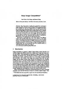
The simulator acts as an environment for generating percepts and consuming actions. In other work we have integrated a BDI agent platform (JACK) with an agent based simulation platform (Repast) via percepts and actions with message passing that synchronises the two systems. In the integrated model, each BDI agent that interacts with the simulation environment has a corresponding simulation agent that acts as a sensor-actuator for sending percepts from the environment to the BDI agent and executing actions of the BDI agent within the simulated environment (See Figure 13). While it is possible to achieve the same with a single simulation agent, having individual simulation agents provide an independent thread of execution for each agent and also simplifies the implementation. Agent System
with information to be contained in the percept, which corresponds to a particular test case. It is possible to identify which agent handles the triggering percept for the particular scenario from the design specification using the traceability links as described in section 2.1. For example, in the BookOrder scenario the data required by the SalesManager agent to populate the BookOrderPercept such asorder details will be provided by the SIM-TA. These state variable initialization is achieved by calling the appropriate “set methods” of the simulation agents. • Once the above set-up process is complete (including receiving the action StartSimulation from BDI-TA) the SIM-TA starts the execution of the rest of the simulation agents. For example in the BookOrder scenario, this will make the SalesManager simulation agent send the BookOrderPercept to the SalesManager BDI agent. Once the system execution starts the SIM-TA does not interact with any of the agents in the system as part of the usual execution, but simply records actions generated and percepts received.
Simulation Environment P A
A
A P A
B B
P A
C
• Any action produced by an agent is executed via its corresponding simulator agent, which simulates the effects of the action on the environment. Which may in turn produce percepts. For example, the PaymentManager agent produces the PaymentRequest action, which when executed in the simulator generates the PaymentDetailsPercept which is delivered back to it.
C
P A
Test Agent Test Agent
A = Action
P = Percept
Figure 13: Interaction with the Sim environment
• Apart from action triggered percepts, the scenario may also require percepts at particular time intervals, or when a particular state of the environment is true. Simulator agents execute routines at every simulation cycle. Therefore, the tester/developer should encode the routines for producing these percepts within the corresponding simulator agents. It might also be the case that not sending an intermediate percept is part of a test case that tests the behavior of the system when the percept is not received (does the system fail gracefully?).
For the purpose of testing the system, we introduce a BDI Test Agent (BDI-TA) and a Simulator Test Agent (SIMTA), to set up and execute the test cases. Whilst the BDITA will be able to directly access and set-up any system level information, in order to set-up information that is internal to an agent, each agent is required to have a HandleTestData plan which is triggered by a TestData message sent by the BDI-TA. An overview of the testing process is as follows:
• The test case execution ends when a pre-defined timeout is reached for the complete scenario execution. It could also end if a pre-defined timeout for a particular action is not met.
• The SIM-TA sends the relevant test data, such as the initial values for the test variables and initialization procedures to the BDI-TA via a StartTest percept which is handled by the HandleStartTest plan in the BDI-TA. This marks the start of a test case execution. The test descriptor for the scenario to be tested is used to determine the appropriate information that needs to be initialized.
• All the actions and percepts generated during the execution of a particular test case is recorded. The data for all test case executions for a particular scenario is gathered and later analyzed. Note that we currently only support the testing of a single scenario at a time. We assume the execution of the scenario under test in isolation where interacting scenarios are not considered. Testing interacting scenarios is part of the future work. In order to assist the developer in the above process the following automated code generation can be performed:
• The BDI-TA sets up any system level information and runs initialization procedures and sends a TestData message to the relevant agents for setting up agent internal beliefs or variables. For example, in testing the BookOrder scenario, the value for the variable stock quantity and the initDB initialization procedure will be established by the SalesManager agent (refer Figure 5). When all initializations are complete, the BDI-TA informs the SIM-TA of this by sending the action StartSimulation.
• Using the design specification it is possible to obtain the percepts and actions relevant to a particular agent. The code stubs for executing these actions and generating the percepts are created in the corresponding simulator agent which the developer can then fill-in.
• The SIM-TA also provides the simulator agents that may generate percepts during the scenario execution
291
• When generating test cases, the initialization procedures and variables are extracted from the test descriptor of the scenario and presented to the user as a test specification. The user can then set the values of the variables that form the different test cases.
simultaneous scenarios are in execution giving rise to actionpercept sequences influenced by each other. More work is required in supporting the test developer and extending the simulation environment to be able to support interacting scenarios. To our knowledge this is the first work that explores the use of an agent simulation platform as a test automation tool to test an agent system. We intend to explore this further in two directions. Firstly, we intend on evaluating our framework by testing several agent systems from different application domains in order to gain further insight into the effectiveness of our approach. Secondly, we plan to extend the PDT design interfaces to allow developers to graphically define the simulation agent details, providing a unified interface for designing system(BDI) and test(SIM) agents.
• The code stubs of the SIM-TA, BDI-TA and the HandleTestData plan for each agent are created. The specification of the variables that influence a scenario in the test descriptor of that scenario allows automated test case generation, using the domain range for the variables and any comparative relationships specified. Such an approach is already fully implemented in PDT for the unit testing framework of Zhang et al. [12].
5. DISCUSSION/CONCLUSION
6.
In this paper we have extended the specification of scenarios in Prometheus methodology to include information that allows (a) a structured specification of the variations of a given scenario in terms of percept and action sequences; (b) traceability of the scenario throughout the various design stages; and (c) the scenario to be tested for the expected outcomes in terms of the specified percept and action sequences. We then provide a detailed process for mapping scenarios to implementation, using the Prometheus Design Tool, automatically propagating information where possible. Finally, we provide an approach for testing the scenarios, using an agent based simulation platform. Given the nature of an agent system behavior, which includes asynchronous handling of percepts from the environment and simultaneous execution of multiple intentions (plans), it is not trivial to use standard test automation frameworks for testing agent systems. Moreover, existing scripting based automation tools [3] require extensive set up to simulate a complex environment that an agent system operates in. Therefore, we use an agent simulation platform such as Repast for simulating the environment for the agent system and enabling the test case execution for scenarios. While formal verification is one approach that can be used for validating requirements (such as the Z specification), these methods require additional knowledge in the developers part to apply them and are also not well supported by practical agent implementation platforms (such as JACK) based on main stream programming languages (such as Java). Hence, even if the design model is verified, the implementation should still be tested via a practical approach as proposed in this work. The testing approach developed compliments other work on testing agent systems such as the unit testing framework of Zhang et. al. [12] which we build upon, the goal-oriented testing approach of the eCAT tool [5] which is based on the goal models associated with the Tropos methodology [4], the JAT framework [2] for testing agents developed in the JADE platform 7 that specifies a fault model based on general agent features and provides skeleton code for testers to manually develop test cases and the SUNIT framework based on the SEAGENT model [10]. One of the limitations of the current approach is that it tests a given scenario in isolation. This simplification has helped us focus on building a framework for using scenarios for system testing. However, in a “live” agent system 7
REFERENCES
[1] Steve S. Benfield, Jim Hendrickson, and Daniel Galanti. Making a strong business case for multiagent technology. In Proceedings of AAMAS’06, pages 10–15, New York, NY, USA, 2006. ACM. [2] Roberta Coelho, Uir Kulesza, Arndt von Staa, and Carlos Lucena. Unit Testing in Multi-Agent Systems using Mock Agents and Aspects. In Proceedings of the 2006 International Workshop on Software Engineering for Large-Scale Multi-Agent Systems, pages 83–90. ACM Press, 2006. [3] Mark Fewster and Dorothy Graham. Software test automation: effective use of test execution tools. ACM Press/Addison-Wesley Publishing Co., New York, NY, USA, 1999. [4] Fausto Giunchiglia, John Mylopoulos, and Anna Perini. The tropos software development methodology: processes, models and diagrams. In AAMAS ’02: Proceedings of the first international joint conference on Autonomous agents and multiagent systems, pages 35–36, New York, NY, USA, 2002. ACM. [5] Cu D. Nguyen, Anna Perini, and Paolo Tonella. ecat: a tool for automating test cases generation and execution in testing multi-agent systems (demo paper). In 7th International Conference on Autonomous Agents and Multiagent Systems (AAMAS 2008), Estoril, Portugal, May 2008. [6] Michael J. North, Nicholson T. Collier, and Jerry R. Vos. Experiences creating three implementations of the repast agent modeling toolkit. ACM Trans. Model. Comput. Simul., 16(1):1–25, 2006. [7] Lin Padgham, John Thangarajah, and Michael Winikoff. Prometheus design tool. In Proceedings of The AAAI Conference on Artificial Intelligence, pages 1882–1883, Chicago, USA, 2008. [8] Lin Padgham and Michael Winikoff. Developing Intelligent Agent Systems: A practical guide. Wiley Series in Agent Technology. John Wiley and Sons, 2004. [9] Leon Sterling and Kuldar Taveter. The Art of Agent-Oriented Modeling. The MIT Press, 2009. ¨ [10] Ali Murat Tiryaki, Sibel Oztuna, Oguz Dikenelli, and Riza Cenk Erdur. Sunit: A unit testing framework for test driven development of multi-agent systems. In AOSE, pages 156–173, 2006. [11] Zhiyong Zhang, John Thangarajah, and Lin Padgham. Automated unit testing intelligent agents in pdt. In AAMAS ’08: Proceedings of the 7th international joint conference on Autonomous agents and multiagent systems, pages 1673–1674, Estoril, Portugal, 2008. [12] Zhiyong Zhang, John Thangarajah, and Lin Padgham. Model based testing for agent systems. In 10th International Workshop on Agent Oriented Software Engineering (AOSE2009), Budapest, Hungary, May 2009.
jade.tilab.com/
292