The presented algorithm aims at minimization of the program execution time. It assigns tasks to processors and interâtask shared memory communication to.
Scheduling Moldable Tasks for Dynamic SMP Clusters in SoC Technology Lukasz Masko1 , Pierre–Francois Dutot2 , Gregory Mounie2 Denis Trystram2 , Marek Tudruj1,3 1
Institute of Computer Science of the Polish Academy of Sciences ul. Ordona 21, 01–237 Warsaw, Poland 2 Laboratoire Informatique et Distribution – IMAG 51 rue J. Kuntzman, 38330 Montbonot St. Martin, France 3 Polish–Japanese Institute of Information Technology ul. Koszykowa 86, 02–008 Warsaw, Poland E-mail: {masko, tudruj}@ ipipan.waw.pl, {pfdutot, mounie, trystram}@ imag.fr
Abstract. The paper presents an algorithm for scheduling parallel programs for execution in a parallel architecture based on dynamic SMP processor clusters with data transfers on the fly. The algorithm is based on the concept of moldable computational tasks. First, an initial program graph is decomposed into sub–graphs, which are then treated as moldable tasks. So identified moldable tasks are then scheduled using an algorithm with warranted schedule length.
1
Introduction
The paper concerns task scheduling in parallel programs based on the notion of moldable computational tasks. Moldable Tasks (MT) [3] are parallel tasks, which can be executed using an arbitrary number of parallel processors. Such tasks have been used as atomic elements in program scheduling algorithms with warranty of schedule length [1, 3, 2]. Parallel execution cost of MTs for variable number of executing processors is characterized by its penalty function, which determines task execution efficiency versus an ideal parallel execution on the given number of processors. For program execution a special shared memory system architecture is used. It is based on dynamic processor clusters, organized around shared memory modules. Data reads on the fly are provided in these clusters which means that processors in a cluster can read data which are written or read to/from a memory module through an internal data exchange network. Processors can be switched between clusters with data in their data caches. After switching, a processor can write data from its cache to the memory allowing the data to be read on the fly by other processors in the cluster. Such operation i.e. processor switching followed by the read on the fly is called ”communication on the fly”. Dynamic SMP clusters are organized inside integrated system on chip (SoC) modules which are connected by a central global interconnection network. The global network enables direct global communication between all processors in the system and all memory modules.
a)
b)
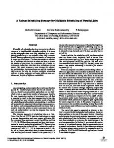
Fig. 1. General system structure (a) and architecture of a single SoC module (b)
The presented algorithm aims at minimization of the program execution time. It assigns tasks to processors and inter–task shared memory communication to dynamic processor clusters. It converts standard communication into reads on the fly and communication on the fly. Communication is analyzed at the level of data exchanges between processor data caches. The paper is composed of two parts. The first part outlines the assumed system architecture. The second part describes the algorithm for scheduling an application program graph in SoC modules containing dynamic SMP clusters based on Moldable Tasks approach.
2
Dynamic SMP clusters and communication on the fly
General structure of the parallel SMP architecture is presented in Fig.1a. A system consists of multiprocessor SMP modules containing processors (P) and shared memory modules (M) connected via local interconnection network (Local Network), implemented as System–on–Chip module (SoC). A number of such modules is connected via global interconnection network (Global Network). The architecture of a single SoC module is presented in Fig.1b. A module consists of a number of processors and shared memory modules. Every memory module has its own, dedicated local network. This architecture is based on the idea presented in [6] with assumption, that a single module has a limited number of processors and memory modules. This constraint is derived from limited communication efficiency of a memory bus for a bigger number of processors. Every processor has a multi–ported data cache memory. It can be connected at a time to many memory modules via local networks. A set of processors connected to the same local network (memory bus) constitutes a cluster. A processor can be dynamically switched between clusters on demand. Inside a cluster, a very effective intra–cluster communication method called reads on the fly is provided. It consists in parallel reads of the data, which is being read or written to a shared memory module by many processors connected to the same bus, which need this data for their computations. Also a new inter–cluster communication method has been introduced, which takes advantage of both
processor switching between clusters and data reads on the fly — communication on the fly [6]. All data transfers as well as processor switchings between busses are supervised by memory bus arbiters. On processors’ side, they are arranged by processors’ Bus Request Controllers, which are connected to all memory bus arbiters manage local queues of processor’s requests and perform data transfers on the fly. The details of the assumed cluster architecture are given in [6, 7].
3
The scheduling algorithm
We are given a program macro data–flow graph and an executive system of interconnected dynamic SMP clusters, with N processors and M memory modules. The proposed scheduling algorithm consists of the following steps: 1. Definition of Moldable Tasks (MT) inside program graph. This part is based on a standard DSC algorithm. The basic assumption is that the nodes which correspond to the same MT are mapped to the same SoC module. Also the size of such task depends on a size of a SoC module. All defined MTs also fulfill certain criteria on their external communication. 2. Determining the penalty function for each moldable tasks. This step consists in scheduling these MTs for a range of available resources. For every number of available processors and memory buses the best scheduling of each MT in the program graph is found. 3. Assignment of resources (allotment) to each MT and their scheduling. In this step both processors and memory buses are assigned. So btained tasks are then scheduled using modified list scheduling assuming that all processors which are assigned to a task belong to the same SoC. 3.1
Step 1 – definition of Moldable Tasks
In this step, the initial program graph is divided into subgraphs. Each such subgraph constitutes a separate Moldable Task. Every such task can be characterized by the following rules: 1. The smallest possible task subgraph is constituted by only one computation node. The maximum size of a MT’s program graph is limited. 2. All external reads (i.e. reads from nodes assigned to separate MTs) can be performed only at the beginning of the task. It means, that if for any node v, the task subgraph contains also its predecessor u, it must contain all its predecessors. 3. All external writes (i.e. writes to nodes assigned to separate MTs) can be performed only at the end of the task. It means, that for any node u, if the task contains any of its successors v, it must contain all its successors. A single MT is executed entirely inside a single SoC module, which means, that global communications can exist only between separate MTs. It is assumed, that each task can be scheduled only inside single SoC module.
The algorithm is based on a clustering technique and on an observation, that converting a standard read operation to a read on the fly removes this read node from linear execution time of the graph. This read operation is then performed on the fly while the write takes place. In the initial structuring, all the nodes from the initial macro dataflow program graph constitute separate MTs. It is assumed, that all data transfers between separate MTs are executed via global communication network. The algorithm creates new larger MTs by merging smaller tasks. The reduction in execution time is obtained by transforming global communications between separate small tasks into local communications performed inside a larger task. Such local communications may be executed on the fly, which further reduces their execution time. This part of the algorithm uses a macro dataflow reprezentation of the program graph. At the beginning, every computation node of the initial program graph constitutes a separate MT. As mentioned above, such tasks are then merged to obtain larger MTs. Everytime a set of MTs is merged to create a larger MT, all the nodes from this set are substituted with one single node representing the new task. This node must remember its internal structure, which is used in case of further mergings. The weight of this “meta–node” is equal to optimal execution time of the subgraph which it represents. In order to obtain MTs which obey rules 2 and 3 described above, the new “merging” operation of MTs must be defined. The algorithm which merges two MTs is presented as Algorithm 1. In a standard DSC algorithm merging two parallel clusters and mapping them onto the same processor reduces communication between them (edge weights become 0), and all computation nodes have to be performed sequentially. In our algorithm, mapping of parallel subgraphs onto the same SoC module means only, Algorithm 1 Entry data: MTs graph G and its two nodes u and v. There exists an edge from u to v in G. To every node of G assign boolean attributes d and p and mark both of them as unchecked. Create two sets D and P . Insert u into D and mark it as visited. T = ∅ is a subgraph, which will contain the result of “merger” of u and v. while any of sets D and P is not empty do for every element t of set D do add t node to the task subgraph T , mark its d property as checked. insert all unvisited descendants of t, which have their p property unchecked, into set P and remove t from D. end for for every element t of set P do add t node to the task subgraph T , mark its p property as checked. insert all unvisited predecessors of t, which have their d property unchecked, into set D and remove t from P . end for end while Subgraph T constitutes a new MT, which merges initial tasks u and v. Find execution time of T by symbolic evaluation of a subgraph, which corresponds to it.
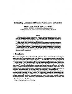
that these subgraphs are executed using the same set of processors. If this set is large enough, they can be still performed in parallel. This introduces a new problem – how to decide, if we should map two parallel subgraphs onto the same SoC. The decision depends on the graph as well as on the number of resources available inside the SoC module (i.e. processors and memory modules). A set of MTs can be merged to create a new MT only if a resulting task can be scheduled on a single SoC module in an efficient way, therefore the size of a single MT must be limited, depending on both computations and communications. The constraints on a number of required processors can be easily checked using symbolic execution of a macro dataflow graph of a task assuming, that all communications are performed on the fly. In order to check communication constraints, a communication activation graph (Fig.2c) is defined in the following way: – All the communications inside the task are performed using reads on the fly. Only initial data reads from the shared memory and final writes to the shared memory are executed in a standard way. – The nodes in the communication activation graph correspond to communications (one node per one on the fly subgraph and one node per standard communication). The weight of each node is equal to execution time of a subgraph corresponding to it (or a single communication in case of standard data transfers). – Edges in this graph correspond to computations and connect nodes depending on a structure of an initial macro dataflow program graph. Their weights are equal to weights of computation nodes in an initial program graph. For a given task T , two following functions are defined: T • Fcomp (t) – this function is determined by projection of execution times of com-
a)
b)
c)
Fig. 2. Example of a task graph (a), its extended macro dataflow representation (b) and communication activation graph (c)
putation nodes of task T on a time axis. It describes the number of potentially concurrent computation nodes, which are executed at time point t. T • Fcomm (t) – This function is determined by projection of execution times of nodes in a communication activation graph of task T . It describes the number of concurrent communications on the fly, which are executed at time point t. The execution times of a communication activation graph can be determined in parallel with determining execution times of nodes and edges in a standard macro dataflow program graph. The algorithm assumes, that, for any task T , at any moment of its execution, these functions fulfill the following constraints: T Fcomp (t) ≤ N,
T Fcomm (t) ≤ M
where N is a number of processors and M is a number of shared memory modules (and local memory busses) in a SoC module (in the paper it is assumed, that N = M ). This implies, that at any moment during execution of task T , all possibly parallel computations and communications will have enough resources to be executed in parallel. The first part of the scheduling algorithm is presented as Algorithm 2. After it is executed on the initial program graph, the set of computation nodes is divided into subsets. These subsets will constitute Moldable Tasks for further steps of the presented scheduling algorithm. 3.2
Step 2 – determining the penalty function for defined MTs
The goal of this step of the algorithm is to determine the penalty function for each MT created in the previous step. For every such MT, this operation consists in finding the best schedule of this task for a range of processors n ∈ (1 . . . N ), Algorithm 2 Define the Moldable Task graph G from the initial macro dataflow program graph (the computation tasks from the initial program graph correspond to MTs in this graph, edges connect tasks like in the initial program graph). Mark all edges in G as unvisited. while there exists an unvisited edge in G do Find a critical path of the graph using its symbolic execution. Select the heaviest unvisited edge from the critical path. If there is no such edge, select the heaviest edge from the other unvisited edges in G. The selected edge defines two nodes u and v from G, which it connects. Find a new MT T by “merging” nodes u and v using Algorithm 1. Determine communication activation graph from the macro dataflow graph of T . T T Determine functions Fcomp (t) and Fcomm (t). T T if for any t, Fcomp (t) ≤ N and Fcomm (t) ≤ N then Create a new MT graph G0 from G, in which all the nodes corresponding to task T are substituted by node of task T . Assign G := G0 else Reject task T . Mark the selected edge as visited. end if end while
where N is the number of processors in a SoC module. For a given pair (T, n) (T is a MT, n is a considered number of processors), the 2–step algorithm is used, which first maps all the computation nodes of this tast to n processors inside a SoC module, and then finds the best structuring of so mapped nodes, which gives the best execution time. It is assumed, that all initial communication comming into a considered MT is ready and may be executed when required. It also assumes, that all final data transfers to shared memory modules can be executed as soon as the data are ready. First, nodes of a program graph of the considered MT T are mapped to a limited number of processors, which is a parameter of the algorithm. This step uses a standard macro dataflow program graph notation. It also assumes a simple architecture model, in which all the processors are connected with a full interconnection network and data transfers are performed using simple point– to–point communications. The second step uses an extended macro dataflow program graph notation. It transforms communications to be performed using data transfers on the fly. It also assumes such constraints as the number of local memory buses, to which a processor may be simultaneously connected. Because all the nodes are mapped to processors in a single SoC module, no global communication is used and all communications are executed using a local, bus–based interconnection network connecting processors with shared memory modules. Distribution of program nodes between processors At the beginning, all the computation nodes of the program graph of a considered task T are distributed between all the processors in a single SoC module. In this step a standard macro dataflow graph of the program is used. It is assumed that all processors are connected to each other via a full interconnection network. If two adjacent computing nodes are mapped to the same processor, communication between them has cost 0. Otherwise, it is equal to the weight of an edge between these nodes. This is similar to a standard clustering technique [4] and corresponds to transformation of data transmissions via shared memory modules to transfers of data in processors’ data caches. The distribution is performed using a list scheduling algorithm with ETF heuristics [5] with a modified selection method for choosing a processor, on which a computation node will be mapped. In the presented list algorithm also all the processors are considered, on which predecessors u of the task v were executed. The selection algorithm consists in checking the following possible mappings and selecting the one, for which execution of the task v is the earliest: – Check, if any of processors, on which one of predecessors of v were executed, is idle at the moment. If yes, choose it and map the task v on it. In case when more than one such processors are available, that one is selected (u), for which communication between tasks v and u is the biggest. – If there are no such processors (all such are busy at the moment), check the following possibilities and select the one, for which v completes earlier: • Select the first available processor and map v on it.
• Try to map v one by one to all of the processors, on which its predecessors have been executed. In all these cases, the actual execution of a task is delayed, depending on communications from all of its predecessors. If t is executed on the same processor as one of its predecessor t0 , communication cost between these t and t0 is equal to 0 and the delay is determined by the remaining communications to the node t. This happens due to assumption, that between two consecutive computation nodes executed on the same processor, data may be transferred in processor’s data cache, what reduces communication time to 0. This is similar to a standard clustering technique. Structuring a mapped program graph In this step, a scheduled task program graph is structured to convert as many communications between processors as possible into data transfers on the fly. This step is based on atomic subgraphs and their basic transformations, as described in [8], but the presented algorithm introduces improvements to ajust to different conditions. In the previous algorithm, at the beginning, all the program graph nodes were mapped to separate processors and the number of processors was potentially unbounded. During scheduling this number was reduced. In an extended macro dataflow graph in this algorithm all edges from the initial macro dataflow graph were converted to pairs of write and read nodes, because all communications were executed initially between separate processors. In the algorithm presented in this paper, after the first step, all the nodes are already mapped to target processors. It means, that for most of communications the decision has already been taken, if they would use inter–processor communication networks, or if the would be performed using processors data caches. In the latter case, there are no write and read nodes in extended macro dataflow graph. The algorithm consists in traversing a program graph, selecting basic subgraphs in it and transforming them into equivalent forms, in which all possible data transfers are performed on the fly. The traversal of the program graph is performed using heuristics based on a Dominant Sequence. In the presented model, any path in a graph consists not only of computation and communication nodes, but it also includes interaction of processors with arbiters (both data transfers and processor switching between memory modules) and synchronization. Therefore, it is required to introduce an equivalent of “the heaviest edge on the path”. In an extended macro dataflow program graph such structure is called “communication subgraph”. It is a subgraph containing a read node, a write node which precedes this read in the graph and nodes of arbiters, which control both transmissions (together with all edges connecting these nodes). A basic structure is a local subgraph corresponding to one of the following communication schemes: one to many communication scheme (broadcast), many to one communication scheme (reduction), many to many communication scheme (butterfly). For a given program graph, the presented algorithm calculates a dominant sequence using simulated execution of a graph. Then, it selects the heaviest
Algorithm 3 Initialize the set S by inserting into it all nodes, which do not delay completion of a barrier. Sort all other read nodes from the considered subgraph in an ascending order, according to their ready time, and place them in a queue Q. The nodes, which are ordered last delay execution of the barrier the most. Transform the initial subgraph by converting all nodes from the set S to reads on the fly. Determine execution time T0 of the transformed program graph. while queue Q is not empty do Pick the first node q from queue Q Transform the initial subgraph by converting all nodes from the set S ∪ {q}. Determine execution time t of the transformed program graph. if t ≤ T0 then S := S ∪ {q}; T0 := t else Break the loop end if end while The set S contains nodes, which should be included in a transformation.
unexamined communication subgraph on this path. Next, a basic structure is selected, which contains this subgraph. Finally, the selected subgraph is subject to proper transformation. As a result, an equivalent program graph is obtained, in which the most important (the heaviest) communication is transformed from a transfer via shared memory to data transfer on the fly. The transformations try to convert standard data transfers into reads and communications on the fly by introducing barriers, converting standard read nodes to proper read on the fly nodes and adding processor switchings, if required [8]. All transformations of basic structures introduce synchronization, which is necessary for proper execution of data reads on the fly. Barriers may entail delays in program execution. Therefore, in some cases it is necessary to exclude some nodes, if their transformation causes unacceptable delays in program graph execution. The algorithm, which determines the nodes, which should be included in the transformation, is presented as Algorithm 3. It is executed separately for every subgraph related to every write node (in fact to a barrier, which must be introduced to convert this write to data transfer on the fly) located in a considered basic structure. 3.3
Step 3 – resources allotment for MTs and final scheduling
In this step, every MT obtained in previous steps is assigned a number of resources which will be used for its execution. It can be performed for instance with the algorithm described in [2]. This algorithm finds allotment of processors to MTs, which finds a tradeoff between workload and length of a critical path in a graph. Definition of MT from previous steps assures, that every task will be assigned to no more processors than the size of a SoC module. As a result, a MT graph is transformed into a standard tank graph with each node arranged to be
Algorithm 4 Select all MT, which have no predecessors in the MT graph. Their ready time is 0. Insert the selected MTs into a priority list L (priority of a task is its ready time). while While the list L is not empty do Select the first MT from the list. Look for a SoC with enough number of available resources to start this task at its ready time. The number of required resources for every MT is defined in step 3 of the algorithm. if there is such SoC then Assign the task to free processors and intra–cluster communication networks in this module. This determines completion time for this task and is done using the characteristics obtained in step 2. else There is no such module available at a time, so select the one, which will be the first available in the future. Check completion time of the examined MT in case it is assigned to this module, assuming the penalty function and task execution time obtained in step 2. Also try to assign the selected MT assuming the lower number of resources available to all modules, on which it can be started earlier. Select the assignment with the shortest completion time of this MT is the lowest. Map the task to the selected SoC module and its resources, according to this selection. end if Examine all descendants of this task and select these, for which their predecessors have been scheduled. Adjust their ready time according to completion times of their predecessors and insert them to list L. end while
executed with a fixed number of processors. To schedule it, we use a modified list scheduling algorithm with ETF (Earliest Task First) heuristics. This algorithm is presented as Algorithm 4. After the graph has been structured, every computation node is assigned to a processor and all communication is assigned to intra–cluster (communication between MTs mapped to the same SoC module) or inter–cluster communication networks (communication between MT mapped to different SoC modules). Finally, communication between consecutive MTs mapped to the same SoC module should be converted back to data transfers on the fly.
4
Conclusions
The paper has presented an algorithm for scheduling parallel programs given in a form of task graphs for a parallel architecture based on dynamic SMP processor clusters with data transfers on the fly. The algorithm uses the concept of Moldable Tasks. It decomposes an initial program graph to sub–graphs, which are treated as MTs. It is done according to communication layout in the program graph, trying to reduce global communication between SoCs. So defined MTs are scheduled using an algorithm with warranty of schedule length.
References 1. D. Trystram, Scheduling Parallel Applications Using Malleable Tasks on Clusters, Proc. of the 15th IPDPS, IEEE CS Press, 2001. 2. R. Lepere, D. Trystram, G. J. Woeginger, Approximation algorithms for scheduling malleable tasks under precedence constraints, 9th Annual European Symposium on Algorithms, LNCS, Springer Verlag, 2001. 3. A. Chernykh, D. Trystram, On–line Scheduling of Multiprocessor Jobs with Idle Regulation, Fifth Intl. Conf. on Parallel Processing and Applied Mathematics, PPAM 2003, Czestochowa, Poland, Sept.2003, LNCS 3019, Springer Verlag, 2003. 4. T. Yang, A. Gerasoulis, DSC: Scheduling Parallel Tasks on an Unbounded Number of Processors, IEEE Transactions on Parallel and Distributed Systems, Vol. 5, No. 9, 1994. 5. J.Y–T. Leung, J.H. Anderson, Handbook of scheduling. Algorithms, models and performance analysis, Chapman and Hall, 2004. 6. M. Tudruj, L. Masko, Communication on the Fly and Program Execution Control in a System of Dynamically Configurable SMP Clusters, 11th Euromicro Conference on Parallel Distributed and Network based Processing, February, 2003, Genova, Italy, IEEE CS Press. 7. M. Tudruj, L. Masko, Dynamic SMP Clusters with Communication on the Fly in NoC Technology for Very Fine Grain Computations, International Symposium on Parallel and Distributed Computing ISPDC 2004, Cork, Ireland, July 2004, IEEE CS Press 8. L. Masko, Atomic operations for task scheduling for systems based on communication on–the–fly between SMP clusters, 2nd ISPDC, Ljubljana, October 2003, IEEE CS Press.