static, such as base stations in packet radio networks, or mobile, such ... Broadcast is an important opera- ..... Forwarding List(FL) records the IDs and transmis-.
Scheduling of Broadcasts in Multihop Wireless Networks Pei-Kai Hung, Jang-Ping Sheu, and Chih-Shun Hsu Dept. of Computer Sci. and Info. Eng., National Central University Chung-Li, 320 Taiwan, R.O.C. �dw, sheujp, cshsu�@axp1.csie.ncu.edu.tw ABSTRACT Broadcast is an important operation in wireless networks. However, broadcasting by naive flooding causes severe contention, collision, and congestion, which is named the broadcast storm problem. Many protocols have been proposed to solve this problem, with some investigations focusing on collision avoidance yet neglecting the reduction of redundant rebroadcasts and broadcasting latency; while other studies have focused on reducing redundant rebroadcasts yet have paid little attention to collision avoidance. Two one-to-all broadcast protocols based on two schemes are proposed herein. The set-covering scheme reduces redundant rebroadcasts and the independent-transmission-set scheme avoids collision and reduces latency. Furthermore, an all-to-all broadcast protocol is presented based on the one-to-all protocol. Simulation results show that the novel broadcast protocols are efficient and can achieve high reachability. 1. INTRODUCTION Due to advances in wireless communication technology and portable devices, wireless communication systems have recently become increasingly widespread. A wireless network is a collection of hosts that communicate with each other via radio channels. The hosts can be static, such as base stations in packet radio networks, or mobile, such as notebook computers in mobile ad hoc networks (MANETs). If all hosts in a wireless network can communicate directly, the network is single hop, otherwise it is multihop. Broadcast is an important operation in all kinds of networks. However, due to the limited transmission range and bandwidth of a radio channel, the broadcast protocol must be designed carefully to avoid serious contention, collision, and congestion, known as the broadcast storm problem[8]. Broadcast problems in wireless network have been studied extensively in the literature. References [1, 4, 5, 6, 7, 10, 11, 12] attempt to design collision-free neighboring broadcast protocols, and model the broadcast scheduling problem as a graph-coloring problem. The colors in the graphs represent the channels assigned to the hosts(which could be slots, frequencies or codes). Since no host can be assigned the same color (channel) as any of its neighbors within two-hop, collisions can be avoided. The research goal of the protocols presented in [10, 11] is to minimize the assigned colors (channels), while the protocols presented in [4, 12] aim to increase total through� This work was supported by the National Science Council of the Republic of China under Grant NSC 90-2213-E-008-019.
put. Using a different approach, two collision-free protocols for one-to-all broadcast are proposed in [2], one centralized and the other distributed. In the centralized scheme, the source host schedules the transmission sequence using knowledge of global network topology. Unlike the graph-coloring problem, a host can simultansously use the same channel as its neighbors within twohop, provided no collisions occur among the receiving hosts. However, in the distributed scheme, the source host follows the depth first search tree to pass a token to every host in the network. After receiving the token, the host realizes which time slots are collision-free and can then decide its transmission sequence based on this information. The above broadcast protocols are aimed to alleviate the broadcast storm problem: some works [1, 2, 4, 5, 6, 7, 10, 11, 12] focus on avoiding collisions but pay little attention to reducing redundant rebroadcasts and broadcasting latency; other studies [8, 9, 13] try to reduce redundant rebroadcasts, but cannot guarantee a collision-free broadcast. This study proposes two efficient one-to-all broadcast protocols, one for low mobility packet radio networks, and one for high mobility MANETs. Both protocols use the set-covering scheme to reduce redundant rebroadcasts and the independent-transmission-set (IT-set) scheme to avoid collisions and reduce broadcasting latency. The broadcast protocol for packet radio networks is efficient and collision-free but depends on gathering the global network topology. While the broadcast protocol for MANETs is less efficient and cannot guarantee a collision-free broadcasts, this protocol requires only the information of two-hop neighbors. Additionally, an all-to-all broadcast protocol based on the one-to-all protocol is presented herein. Simulation results show that the broadcast protocols presented herein are more efficient than other broadcast protocols in terms of reachability, rebroadcast ratio, and broadcasting latency. 2. PRELIMINARY The network is modeled as a graph � = (�� � ), where � represents the set of nodes (hosts) in the network, and � is the set of links. If �, � � � , then an edge � � ��� �� � � exists if and only if � is in the transmission range of � and vice-versa. Assuming that all links in the graph are bi-directional, i.e., if � is in the transmission range of � , � is also in the transmission range of �. The length of the broadcast packet is fixed. While broadcasting, no carrier sense or collision avoidance procedure is executed before transmission. The network
s
f
a
g
layer 0
l k
e
a
b
c
d
e
layer 1
i
j
k
s b
layer 2
d
j
c
h
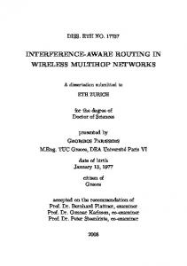
Fig. 1: An example of set-covering problem.
is assumed to be connected. If it is partitioned, each component is treated as an independent network. 2.1. Set-Covering Scheme An example of the set-covering scheme is presented before describing it. In Fig. 1, broadcast source � has information of its one-hop neighbors ( , , �, , �) and two-hop neighbors ( , � , �, �, � , � , �). When node � broadcasts a packet �, the packet will be received by all of its onehop neighbors. However, it is not necessary for all onehop neighbors to forward packet �, since if only nodes a, c, and e are necessary to forward � because they can still cover all the two-hop neighbors of s. Set covering is designed to select the minimum set of �’s one-hop neighbors, which can cover all the two-hop neighbors of �. The nodes in the minimum set serve as the relay nodes of �, thus reducing redundant rebroadcasts. The set-covering problem is defined as follows. Let ��� �� �� be an instance of the set-covering problem, where � denotes the source node, � represents a set of �’s one-hop neighbors, and � represents a set of �’s two-hop neighbors. The set � can be denoted as follows:
� �����
�¾�
� � � is �’s one-hop ���� � �� � � �� � and ���� �� � � �. where node
f
g
h
Fig. 2: A three-layer graph derived from Fig. 1. i
��
l
neighbor and
The set-covering scheme aims to find a minimum set � such that the neighbors of nodes in this set can cover all nodes in � . In Fig. 1, the minimal set � � � � �� �� because the neighbors of nodes in � � �� �� contain all nodes in � . Since the set-covering problem, which can be reduced to the well-known vertex-cover problem, is NP-hard [3], a greedy algorithm proposed in [3] is used to solve this problem. The greedy algorithm works by picking up a node � � � that covers the most remaining uncovered elements in � at each iteration step. The greedy algorithm is shown as follows: Algorithm: Greedy-Set-Cover��� �� Input: �: a set of �’s one-hop neighbors, and � : a set of �’s two-hop neighbors. Output: ��� �����: a set of nodes whose neighbors cover set � . Begin
��� ����� � �; while � is not ���� Select a node � � � that maximizes the size of � ���� � � �; Remove nodes � ���� from � ; Remove � from � and Add � to ��� �����; end while return ��� End
�����;
2.2. Independent-Transmission-Set Scheme Consider a three-layer graph as shown in Fig. 2, which is derived from Fig. 1, where the node in layer 0 is the source node �, nodes in layers 1 and 2 are the one-hop and two-hop neighbors of the source node, respectively. The set � � �� �� in layer 1 is a minimum set, covering all nodes in layer 2. Since nodes , �, and � have no common neighbors in layer 2, they can broadcast packets simultaneously without any collision occuring in layer 2. Consider another case in Fig. 3. The set � � � �� � is a minimum set that covers the nodes in layer 2. However, nodes and share a common neighbor � in layer 2 and nodes and � also share a common neighbor � in layer 2. When nodes , , and � transmit a packet simultaneously, collisions will occur at nodes � and �. Consequently, the independent-transmission-set (IT-set) scheme is employed to arrange the transmission sequences of the nodes in layer 1 to avoid packet collisions in layer 2. The IT-set scheme works as follows. Given a threelayer graph, the set-covering scheme is used to find the minimum covering set, ��� �����. The nodes in ��� ����� are then taken individually to decide their transmission sequence. When the first node is taken, it forms a new independent-transmission (IT) set, and the following nodes are then individually taken from ��� ����� and compared with the nodes in the existing IT sets. If layer 2 contains no common neighbor between the taken node and the nodes in a compared IT set, the node joins the IT set. Otherwise, the node forms a new IT set. Once a new node joins an IT set, the IT sets are sorted in descendent order by the number of nodes in layer 2 covered by the nodes in the IT sets. The IT sets with larger coverage numbers can be compared earlier and have a greater chance of including more nodes in layer 1. Since the nodes in the same IT set share no common neighbors in layer 2, they can broadcast simultaneously. Therefore, the IT-set scheme aims to minimize the number of IT sets and reduce broadcasting latency. For example, executing the IT-set scheme in Fig. 3, obtains two IT sets � � �� � and � �.
s
a
c
b
n
layer 0
layer 1
e
d
g
h
i
j
k
l (2)
w
v (3)
x a(1)
g (2)
p f
m
f (2)
o (3)
layer 2
e (2)
s(0)
b
k (3)
Fig. 3: An example of the IT-set problem. c (1)
d u
h (2)
Before presenting the novel IT-set scheme, the following notations are defined. Let !"���� denote the �-th IT set. Let ����� �� � !"���� represent the number of nodes in layer 2 covered by nodes in !"����. Meanwhile, ��� � !"� is the number of IT sets.
Algorithm: Find-ITS(��� �����) Input: ��� �����: A set of nodes output from the setcovering scheme. Output: !"���: An array of IT set. Initial: ��� � !"� = 0; Step 1: if ��� ����� � � then Return !"���; Let be the first node listed in ��� �����; for � = 1 to ��� � !"� if and every node in !"���� share no common neighbor in layer 2 then �Add to !"����; goto Step 3;� Step 2: ��� � !"� = ��� � !"� + 1; Create a new set !"����� � !"��; Add to !"����� � !"��; Step 3: Remove from ��� �����; for � = 1 to ��� � !"� Calculate ����� �� � !"����; Sort !"��� in descendent order according to the value of ����� �� � !"���; goto Step 1;
3. TWO BROADCAST PROTOCOLS This section presents two broadcast protocols designed for different network assumptions. 3.1. Protocol 1 A collision-free one-to-all broadcast protocol (protocol 1) is proposed for a packet radio network whose network topology is known in advance. Using global information, each node can run protocol 1 to get its transmission sequence and calculate waiting time, and thus each node knows when to forward the received packet to avoid collisions. The assignment of the transmission sequence for each node starts from the source node. The source node is first assigned to transmission sequence ”0”, and its onehop and two-hop neighbors are then put in sets � and � , respectively. The set-covering scheme is applied in each round to pick the minimal relay nodes in �, while the IT-set scheme is employed to divide the minimal relay nodes into different transmission sets. After applying the IT-set scheme, nodes in !"����, which has the
q
i (2)
j (2)
t
r
Fig. 4: A figure shows the result of running protocol 1. The number in the parentheses means the transmission sequence of a node. Nodes not assigned numbers means they are end-points. largest coverage number in the IT sets (!"���), can transmit immediately when they have received the broadcast packet. Accordingly, nodes in !"���� are scheduled and assigned to transmission sequence ”1”. Before executing the next round, the nodes in � and � must be updated as follows. The nodes in the other IT sets are put into set # . The nodes in # and the unscheduled nodes connected to the scheduled nodes in !"���� are put into �. Then the unscheduled nodes connected to nodes in � are put into � . In the next round, the set-covering scheme and ITset scheme are repeated. Nodes in !"���� are assigned to the following transmission sequence ”2”, and nodes in other IT sets are put into set # . The above procedure is repeated until all the nodes are scheduled. When the source node begins to transmit a broadcast packet, its !$ is recorded in the packet header. Meanwhile, when a node receives a broadcast packet, it performs protocol 1 to obtain its transmission sequence. Notably, a node without a transmission sequence is an endpoint and does not need to forward the broadcast packet. For example, in Fig. 4, nodes � , and � receive the broadcast packet form node �. The transmission sequence of node � is ”0”, while that of node is ”1”. Consequently, node will forward the packet as soon as it is received. Meanwhile, node finds it is not assigned a transmission sequence, and thus will not forward the packet. The transmission sequence of node � is ”2”, and thus node � should wait for a ���� ���� to forward the packet, where a ���� ���� is the time spent to forward a broadcast packet. On receiving the broadcast packet with the source !$, each node can perform protocol 1 to obtain its transmission sequence and set the % ����� "����. Once the % ����� "���� expires, the node forwards the broadcast packet to its neighbors. Protocol 1: Initial: � = 1; (� is the transmission sequence of a node.) � = the set of one-hop neighbors of source node �; � = the set of two-hop neighbors of source node �;
While � and � are not empty Step 1: Call Greedy-Set-Cover(�, � ) to find the minimal set ��� �����, which covers all nodes in � . Step 2: Call Find-ITS(��� �����) to find !"���. Assign nodes in the maximal covering set !"���� with transmission sequence � and put the nodes in the other sets of !"��� into set # , � � � � �. Step 3: The nodes in # and the unscheduled nodes connected to nodes in set !"���� are put into �. Then the unscheduled nodes connected to nodes in � are put into � . End While A node � will take one of the following actions when it receives a broadcast packet from node �: A1: If node � is an end-point, it does not need to forward the packet. A2: If the packet has already been received, it will be discarded. A3: If node � is receiving the packet for the first time and node � is not an end-point, it sets % ����� "���� = (the transmission sequence of � � the transmission sequence of � � � ) � ���� ����. Once % ����� "���� expires node � forwards the packet. 3.2. Protocol 2 A one-to-all broadcast protocol for a &'��" (protocol 2) whose nodes have the information of their two-hop neighbors is proposed here. In protocol 2, each sender uses the set-covering scheme to select the minimum number of nodes required for relay from its one-hop neighbors, and uses the IT-set scheme to assign each relay node a proper transmission sequence. Though some collisions may occur among the receiving nodes, simulation results in Section 5 show that protocol 2 has a low rebroadcast ratio and provides acceptable reachability. The following presents an example to illustrate how protocol 2 works. In Fig. 5, source node � assigns a transmission sequence to its one-hop neighbors. Nodes and � are assigned to transmission sequence ”1”, while node � is assigned to transmission sequence ”2”. The scheduled results are recorded in the broadcast packet header and the packet is then forwarded to the one-hop neighbors. Fig. 6 presents the format of the broadcast packet used in protocol 2. In the packet header, the !$ and "� � fields represent the identity and transmission sequence of the sender, respectively. Meanwhile, the (��) � ��� *����(*� records the !$� and transmission sequences of the relay nodes. If a node is scheduled as an end-point, it is not included in the (*. After receiving the broadcast packet from node �, nodes , �, and � in (* will act as node � to schedule the transmission sequence of their one-hop neighbors. Notably, node � will delay for a ���� ���� interval before rebroadcasting. When nodes , �, and � start to schedule the transmission sequences of their one-hop neighbors, they should update their sets of one-hop and two-hop neighbors to prevent from scheduling the nodes which have been scheduled. For example, when node receives the broadcast packet from node �, it updates its sets of one-hop neighbors (�) and two-hop neighbors (� ) by the
n o (3) x
m
a(1)
g(2)
p
l (2)
f(2)
w
v (3)
e (2)
s(0)
b
k (3) d
c (1)
h (2)
Collision
u q
i (2)
j(2)
t (3)
r
Fig. 5: An example to show how a collision happened in protocol 2. Forwarding_ ID TS_my List
ID1 TS1 ID2 TS2
...
Data
IDn TSn
Fig. 6: The format of a broadcast packet in protocol 2.
following rules. R1: Let + denote a set of nodes including sender � and its one-hop neighbors. Removes nodes � + from �. R2: Let , represent a set of nodes which are the onehop neighbors of and � (*. For example, in Fig. 5, , � ��� for node . Remove nodes in + and nodes connected to , from � . Referring to Fig. 5, node should remove nodes �, , and � (which are in set + ) from � because they have been scheduled. Node then removes nodes � and (which are in set + ), and � (which is connected to node � in set , ) from � . Node follows the set-covering and IT-set schemes to assign transmission sequence ”2” to nodes , � and �. Similarly, node � assigns transmission sequence ”2” to nodes �, �, and � , and node � assigns transmission sequence ”3” to node � . Fig. 5 indicates that nodes � and � are all assigned to transmission sequence ”3”. When nodes � and � simultaneously broadcast a packet to next hop, a collision occurs at node �. Since nodes � and � have no way of knowing that nodes � and � share a common neighbor (node �), nodes � and � assign nodes � and � to the same transmission sequence, thus causing a collision at node �. Protocol 2: Begin When a node � receives a broadcast packet � from node � do Case 1: � is received more than once, discard �; Case 2: receiving � at the first time but � is not in the (*, then do nothing; Case 3: receiving � at first time, and � is in the (* do Step 1: Update one-hop neighbors set � and two-hop neighbors set � of �
End
according to rules -� and -�. Step 2: Call Greedy-Set-Cover��� ��; Call Find-ITS(��� �����); Step 3: for � � � to ��� � !"� Assign node � !"���� with transmission sequence "� � � �; Put the node’s ID and transmission sequence into (*; end for % ����� "���� � (the transmission sequence of � � the transmission sequence of � � � ) � ���� ����; As % ����� "���� is expired, forward �;
4. ALL-TO-ALL BROADCAST PROTOCOLS An all-to-all broadcast protocol helps all nodes in the network to efficiently broadcast packets to all other nodes. This section presents an efficient all-to-all broadcast protocol in a TDMA-based network. This protocol can also be applied to �$&' or ($&'-based networks, with a slot being replaced by a code or frequency. The all-to-all broadcast protocol assumes that the broadcast channel consists of frames, with each frame being divided into � slots, where � denotes the number of nodes in the network. Fig. 7 presents the organization of the broadcast channel, where the numbers from 1 to 8 denote the slot numbers in each frame. Meanwhile, the alphabet below each slot number indicates the node that can transmit in this slot. Based on this assumption, two approaches are proposed to solve the all-to-all broadcast problem. The simple approach (named the AA1 protocol), assigns each node to a dedicated slot to initialize and forward the broadcast packets. However, numerous packets can be queued in a high degree node because the node needs to forward the broadcast packets of all its neighbors, and the node in each frame can transmit only one packet. Even in a well-scheduled network [10, 11], where each frame contains fewer slots, the packets are also queued in the high degree nodes. Another approach (named the AA2 protocol) is thus proposed, which is source-oriented and can efficiently solve the problem. This approach forwards each broadcast packet via the source node’s time slot. Consequently, if a node receives many broadcast packets in the previous frame, it can forward them through different time slots in the next frame. Notably, multiple nodes can use the same time slot for transmission if no collision occurs in the receiving nodes. For example, in Fig. 7, when running the AA1 protocol, node receives 5 packets sent by nodes , �, , � , and � in frame 1, and 5 frames are required to forward the 5 packets from slot 2. Meanwhile, when using the AA2 protocol, all the 5 packets received by node in frame 1 can be forwarded in frame 2, in slots 1, 3, 4, 7, and 8. The idea behind the novel protocol is that each node individually performs an independent one-to-all broadcast protocol. Therefore, protocol 1, proposed in Section 3, can be applied to each node to compute the transmission sequences of the received packets.
e a g f b
h
c d
frame 1 frame 2 frame 3 frame 4 AA1 protocol 4 5 6 7 8 3 1 2 4 5 3 6 1 2 7 8 1 2 3 4 5 6 7 8 1 2 3 4 5 6 7 8 Slot a b c d e f g h a b c d e f g h a b c d e f g h a b c d e f g h
AA2 protocol Slot
frame 1
frame 2
frame 3
frame 4
1 2 3 4 5 6 7 8 1 2 3 4 5 6 7 8 1 2 3 4 5 6 7 8 1 2 3 4 5 6 7 8 a b c d e f g h b a a b a c b b c b c a b a a a a a a d c f g h c c b c b b c c
Fig. 7: An example of all-to-all broadcast protocols. Cycle 1
Cycle 2
Node a Frame
1
2
Cycle 1
3
4
Cycle 2
5
6
7
...
6
7
...
Cycle 3
Node b Frame
1
2
3
4
5
Fig. 8: The transmission cycles of nodes and . Meanwhile, when a node initiates a broadcast, its !$ is appended to the broadcast packet and this packet is forwarded via the same slot of each frame. For example, in Fig. 7, nodes , , �, , �, , � , and � all have packets to broadcast to all nodes in the network. First, node transmits its broadcast packet, � �½ , in slot 1 of frame 1, and node ’s neighbors (nodes , �, and �) then receive ��½ . Because nodes and � share a common neighbor , they cannot forward � �½ simultaneously. By applying protocol 1, the transmission sequences of nodes and � for ��½ are ”1” and ”2”, respectively. Therefore, node
will transmit ��½ in slot 1 of frame 2, and node � will transmit ��½ in slot 1 of frame 3. Three frames are required to broadcast � �½ to all nodes in the network and node can then transmit the next broadcast packet, ��¾ , in frame 4. Node can transmit a new broadcast packet for every 3 frames, so the transmission cycle of node can be defined as 3 (frames), as shown in Fig. 8. As node broadcasts packet, � �½ , in slot 1 of frame 1, node successively broadcasts packet, � �½ , in slot 2 of frame 1. Nodes and � can forward � �½ in slot 2 of frame 2, and the transmission cycle of node is 2, as shown in Fig. 8. Similarly, nodes �, , �, , � , and � can also transmit their packets in their dedicated slots. Each node can continuously initialize a new broadcast packet for every transmission cycle, and the packets will not be queued for long in any node. By applying protocol 1, AA2 protocol can not only achieve 100% reachability, but can also efficiently complete the all-to-all broadcast. 5. SIMULATION RESULTS Simulations are used to evaluate the performance of the proposed broadcast protocols. Each node is assumed to be randomly located in a rectangular area. The following parameters are fixed in the simulations: transmission radius (300 meters), packet size (1k bytes), and size of the area (1800 � � 1500 �).
Fig. 9: The rebroadcast ratios of four protocols.
Fig. 10: The average latencies of four protocols.
The performance metrics observed are:
-� �� ���� �-��: ���, where � denotes the number of nodes that receive the broadcast packet and � represents the total number of nodes.
-� �� � ��� � ����--�: ���,
where � denotes the number of nodes that actually retransmitted the broadcast packet and � represents the total number of nodes.
'��� �� � ����
: the interval between the initiation and completion of the broadcast packet.
The performances of our two one-to-all broadcast protocols are compared with flooding and the centralized tree-based (TB) protocol proposed in [2]. The number of nodes is varied to observe how these protocols perform under different node densities. Fig. 9 shows the rebroadcast ratios of the four broadcast protocols. Protocol 1 and protocol 2, which use a set-covering scheme to reduce redundant forwarding, have lower rebroadcast ratios than the flooding and TB protocols. Furthermore, under high node density, the rebroadcast ratios of the three protocols other than flood-
Fig. 11: The reachabilities of four protocols.
Fig. 12: The average latency of the three all-to-all broadcast protocols.
ing are decreasing. The rebroadcast ratio of flooding remains close to 100% because each node rebroadcasts the packets it receives one time. However, the rebroadcast ratios of protocol 1 and protocol 2 decrease with increasing node density, because the higher the node density is the more redundant relay nodes can be reduced by the set-covering scheme. Fig. 10 shows the average latency of the four broadcast protocols. Protocol 1 and protocol 2 finish the broadcast process more quickly than the two other protocols. On average, protocol 1 and protocol 2 finish the one-to-all broadcast in just half the time required by flooding. Protocol 1 and protocol 2 are more efficient than flooding and the TB protocols, they use the IT-set scheme to assign each node a proper transmission sequence avoiding collision and reducing broadcast latency. Fig. 11 shows the reachabilities of the four protocols. Protocol 1 can achieve 100 � reachabilities because the topology is known in advance and each node is well scheduled to avoid collisions. On the other hand, Protocol 2 cannot achieve 100 � reachability because hidden terminal problems may cause some collisions. Meanwhile, although high reachability is possible with flooding, the cost is excessive. Finally, the TB protocol can achieve 100% reachability, because the topology is known in advance, but this protocol is less efficient than the protocol 1. Finally, the performance of three all-to-all broadcast protocols is evaluated herein, specifically AA1 (a simple approach), AA2 (our approach) and the pure greedy approach(PG) [11]. The PG protocol is a collision-free neighboring broadcast protocol in which a vertex randomly selected and colored using a greedy approach. This protocol is simple and efficient. The simulation herein only measures the number of time slot needed for all nodes to broadcast their packets to all nodes in the network. Fig. 12 shows that the AA2 protocol performs better than the AA1 and PG protocols. The AA1 protocol splits each frame into � slots, meaning that some slots are wasted when their packet queues become empty. The PG protocol, which achieves better scheduling than the AA1 protocol, has a smaller frame size, and thus each node has more chance to transmit packets within a certain number of time slots. However, the PG protocol cannot solve the packet queueing prob-
lem, and thus still performs worse than the AA2 protocol. 6. CONCLUSIONS This study proposes two efficient one-to-all broadcast protocols, one for packet radio networks and another for &'��"�. The two protocols can significantly reduce redundant rebroadcasts, and thus avoid contention and collision. The novel protocols are particularly effective under conditions of high node density. Additionally, an all-to-all broadcast protocol is proposed based on protocol 1, and can prevent the broadcasting packets from queuing in the high degree nodes. Simulation results show that the two novel one-to-all broadcast protocols can not only significantly reduce the rebroadcast ratio , but can also reduce broadcasting latency. When broadcasting latency and rebroadcast ratio are considered, the two novel one-to-all broadcast protocols perform better than the flooding and TB protocols. As for the all-to-all broadcast protocols, the novel AA2 protocol finishes an all-to-all broadcast faster than alternative protocols. The novel one-to-all and all-to-all broadcast protocols developed herein are more efficient than previous works because we focus not only on avoiding collisions but also on reducing redundant rebroadcasts and broadcasting latency.
References [1] S. Basagni, D. Bruschi, and I. Chlamtac. A mobilitytransparent deterministic broadcast mechanism for ad hoc networks. IEEE/ACM Transactions on Networking, 7:799–807, December 1999. [2] I. Chlamtac and S. Kutten. Tree-based broadcasting in multihop radio networks. IEEE Transaction on Computers, pages 1209–1225, October 1987. [3] T. H. Cormen and C. E. L. abd R. L. Rivest. Introduction To Algorithms. The MIT Press and McGraw-Hill Book Company, 1 edition, 1990. [4] A. Ephremides and T. V. Truong. Scheduling broadcasts in multihop radio networks. IEEE Transactions on Communications, 38:456 –460, April 1990. [5] M. L. Huson and A. Sen. Broadcast scheduling algorithms for radio networks. In IEEE Military Communications Conference, pages 647–651, July 1995. [6] J. H. Ju and V. O. K. Li. An optimal topology-transparent scheduling method in multihop packet radio networks. IEEE/ACM Transactions on Networking, 6:298 –306, June 1998. [7] C. K. Lee, J. E. Burns, and M. H. Ammar. Improved randomized broadcast protocols in multi-hop radio netwroks. In Proceedings of International Conference on Network Protocols, pages 234–241, October 1993. [8] S. Y. Ni, Y. C. Tseng, Y. S. Chen, and J. P. Sheu. The Broadcast Storm Problem in a Mobile Ad Hoc Network. In Proceedings of the fifth annual ACM/IEEE international conference on Mobile computing and networking, pages 151–162, August 1999. [9] W. Peng and X.-C. Lu. On the reduction of broadcast redundancy in mobile ad hoc networks. In Proceedings of Mobile and Ad Hoc Networking and Computing, pages 129–130, 2000.
[10] S. Ramanathan and E. L. Lloyd. Scheduling algorithms for multihop radio networks. IEEE/ACM Transactions on Networking, 1:166 –177, April 1993. [11] R. Ramaswami and K. K. Parhi. Distributed scheduling of broadcasts in a radio network. In INFOCOM, volume 2, pages 497–504, 1989. [12] A. Sen and J. M. Capone. Scheduling In Packet Radio Networks - A New Approach. In Proceedings of Global Telecommunications Conference, pages 650–654, 1999. [13] J. Sucec and I. Marsic. An efficient distributed networkwide broadcast algorithm for mobile ad hoc networks. http:// citeseer.nj.nec.com/312658.html.