Scheduling using Superposition Coding: Design and Software Radio Implementation P. Vizi, S. Vanka, S. Srinivasa, M. Haenggi, and Z. Gong* Wireless Institute, Department of Electrical Engineering University of Notre Dame, Notre Dame, IN 46556 share of transmit power. The receiver farther away (hereafter called the “far” user) operates at low SINRs; its link capacity is power-limited. This suggests that the near user link benefits from an increased share of bandwidth, while the far user link benefits from an increased share of transmit power. Unlike in schemes such as CDMA, where simultaneous transmission usually implies the use of orthogonal spreading sequences, in SC the waveforms that constitute the composite transmitted signal are not orthogonal to each other, see Fig. 1. Power
Abstract—Cellular base stations typically orthogonalize downlink transmissions, although this approach is not always throughput-optimal. Indeed, it can be shown that removing the orthogonality constraint (as in Superposition Coding) can provide significant benefits in some scenarios. Based on this principle, we propose a scheduling algorithm for a two-user downlink that leverages the disparity in their respective channel qualities. By a judicious reallocation of the transmit power and bandwidth, this algorithm improves the throughput to both users vis-` a-vis an orthogonal scheme. We design a softwaredefined radio platform to implement the scheduler and experimentally verify the gains promised by theory. Index Terms—GNU Radio, Scheduling, OFDM, SoftwareDefined Radio, Universal Software Radio Peripheral, TDM, Superposition coding,
Time
A. Motivation The problem of communicating with two (or more) users often arises in a cellular downlink. Conventional strategies set up this communication by establishing orthogonal channels (typically by time/frequency/code-division) to the users. The QoS supported at a given user thus depends on its share of the “degrees of freedom” (fraction of available timeslots/bands/codes) and transmit power. Even though orthogonal schemes ensure that no two simultaneous transmissions interfere with each other, they are not (informationtheoretically) throughput-optimal [1]. When the requirement of orthogonal transmissions is removed, a wider range of channel access mechanisms become available. One such strategy is Superposition Coding (SC), which refers to the simultaneous transmission of a weighted sum of the waveforms from separately encoded user transmissions over a common frequency band (see Fig. 1). It is known that this strategy can achieve the capacity of a scalar Gaussian broadcast channel [2]. SC essentially leverages the disparity in the channel qualities of the users’ links to provide significant throughput benefits compared to orthogonal schemes. To illustrate its operation, consider two arbitrary users in a cellular downlink. The receiver closer (hereafter called the “near” user) to the base station (BS) decodes signals from the BS at a high signal-to-interference-and-noise ratio (SINR); hence the capacity of its link from the BS is limited by its share of the BS bandwidth (in general by degrees-of-freedom) rather than its *Reverse alphabetical order. S. Srinivasa is the corresponding author. E-mail:
[email protected], Phone: 574-631-5480, Fax: 574-631-4393. The partial support of NSF (grant CNS-1016742) is gratefully acknowledged.
Power
I. I NTRODUCTION
Time Fig. 1. Typical transmission timelines of a two-user downlink with TimeDivision (TD, top) and Superposition Coding (SC, bottom) over a common frequency band. Near-user transmissions are shown in white and those of the far-user in gray. TD maintains orthogonality by transmitting at most one user’s packet at any given time. SC, on the other hand, transmits a linear combination of the individually-coded user waveforms.
Based on the insight above, whenever the far user is to be served, the BS can choose to superimpose (one or more) near user’s packets onto this signal. The near user thus enjoys a greater share of the bandwidth; its share of transmit power can then be reduced, and the savings in power be vested in the transmissions for the far user. The far user thus decodes its packets enjoying a higher SINR. Meanwhile, the near user employs Successive Decoding (SD), i.e., it first decodes the far user packet and thereafter decodes its own packet after canceling the far user’s contribution (interference) to the received signal. By judiciously reallocating transmit power and bandwidth, SC can improve the throughput performances of both users in comparison to orthogonal schemes. The contribution of this paper is two-fold: •
•
We incorporate two key ingredients of SC: code superposition at the transmitter and successive decoding (SD) at the near user to design an intelligent scheduling algorithm that outperforms orthogonal schemes. We design a software-defined radio (SDR) platform to implement this scheduler and experimentally verify the gains promised by theory.
B. Related Work In [3], the authors present an SC-based greedy scheduler for wireless mesh networks, and verify the efficacy of the scheduler via simulations (using ns-2/GNU Radio). In [4], the authors propose a MAC protocol that combines uplink SC and multi-user diversity to improve the throughput around gateway nodes in a mesh network, and present analytical and simulation results (using JiST/SWANS). The performance of the above schemes in a practical setting is, however, yet to be investigated. To the best of our knowledge, we are the first to quantify the benefits of employing SC (vis-`a-vis orthogonal schedulers) via a SDR-based implementation. Amongst other related work, [5] deals with the PHY and MAC layer design of successive interference cancellation for WLANs and its implementation on a SDR platform. [6] considers a 2x2 MIMO system and devises a MAC scheme employing interference alignment and cancellation to improve the link throughput. The performance gain is validated via experimentation on a Universal Software Radio Peripheral (USRP)-based testbed. II. S CHEDULER D ESIGN In this section, we first outline the operation of a simple time division (TD)-based scheduler serving the near and far users. We then propose the design of an enhanced scheduler, which we term the SC-based scheduler. A. The TD-based Scheduler Model The orthogonal scheduler simply separates the transmissions to the two users in time. Suppose that it reserves a fraction uN (resp. uF ), (uF = 1 − uN , 0 ≤ uN , uF ≤ 1) of transmissions1 for serving the near (resp. far) user. We denote the near (far) user’s packet size by !N (!F ) (in bits). The near (far) user is communicated to at a data rate of ρN (ρF ) (in bps). Thus transmitting a packet of user i, (i = N, F) takes τi ! !i /ρi seconds. Therefore, the fraction of time spent for the near (far) user is wN = uN τN /(uN τN + uF τF ) (wF = 1−wN ). Also, suppose that the near (far) user’s packets are transmitted at power PN (PF ). For ease of exposition, we take PN = PF = 1. B. The SC-based Scheduler Model Based on the principle of superposition coding, we propose the following enhanced scheduling policy that builds upon an existing TD-based scheduler. 1) In the time slots assigned for serving the near user, transmit the near user’s data in packets of (same) length !N , at a reduced rate ρ!N = wN ρN ≤ ρN , and a fraction α, 0 ≤ α ≤ 1, of the transmit power, i.e., PN! = α. 2) During the time slots assigned for serving the far user, employ superposition coding to simultaneously transmit (a) the far user’s packets at the earlier rate ρF in packets of size !!F (different from the original size ! ! ! ! !F ) at power 1−α w ! , where wF = uF τF /(uN τN + uF τF ) is F
1 For
instance, transmitting two packets to the near user for every packet to the far user would mean that uN = 2/3.
Pav
...
1 τN Pav
t
τF
(1 − α)/wF!
...
1 τN!
τF!
t
Fig. 2. The first subfigure shows the TD-based scheduler’s timeline for uN = 1/2, i.e., the BS alternates between serving the users. The near (resp. far) user’s packet transmissions are shown in filled (resp. empty) rectangles. The second subfigure depicts the SC-based scheduler’s operation. Here, superposition is indicated by placing the far user’s packets on the near user’s packets. In each subfigure, the y-axis denotes the average transmit power per degree of freedom.
the fraction of the time spent in servicing the far user’s packets, and (b) the near user’s data in packets of size !N at rate ρ!N and power allocation PN! . In subsection III-C, we work out an example to establish that such a design is feasible, and illustrate how to choose the parameters ρ!N , !!F and α (for any given operating point uN ) such that the reliabilities of both users’ links are improved. Fig. 2 compares the timelines for the two different schedulers: TD-based, and SC-based, for uN = 1/2. Notice that while the near user enjoys a greater share of bandwidth (compared to the TD-based scheduler), the far receiver enjoys a higher SINR (provided (1 − α)/wF! > 1). III. S CHEDULER I MPLEMENTATION A. Platform We adopt a software-centric paradigm to implement our design. All the signal processing algorithms at the baseband are implemented digitally using GNU Radio (version 3.3.1) on a general-purpose computer. This approach also allows us to use several built-in libraries that come with the GNU Radio package, including the Universal Software Radio Peripheral (USRP) interface, which acts as the RF and analog frontend. The design uses Orthogonal Frequency Division Multiplexing (OFDM) (with 16 tones) as the transmission scheme. We chose OFDM since it offers a high degree of bandwidth scalability and implementation flexibility, especially given its relative ease of time- and frequency-synchronization, channel estimation and equalizer design [7]. B. System Parameters and Block Diagrams The system parameters used in the experiment are provided in Table I; the transmitter and receiver block diagrams are shown in Figs. 3 and 4 respectively. For lack of space, we omit a detailed description of the subsystems. Interested readers may refer to our earlier paper [8]. From Figs. 3 and 4, it is clear that the scheme is simple enough to implement on current cellular networks. The far-receiver is just a conventional single-user receiver. The near-user (ignoring a
Link Layer
Physical Layer
Near User Queue
Encoder
Modulator
S/P
Far User Queue
Encoder
Modulator
S/P
√
α
USRP
+
√
Insert Pilots
IFFT
Insert CP
P/S
Add Training Sequences
TX Filter
TX Frontend
1−α
Fig. 3. Block diagram of the transmitter. The Serial-to-Parallel (S/P) function accepts serial data at its input and outputs data as blocks of the desired size (in this case the number of subcarriers, 16). The Parallel-to-Serial (P/S) function inverts this operation. CP stands for Cyclic Prefix.
Physical Layer
Successive Decoding
USRP
RX Frontend
Coarse Freq. Correction
RX Filter
Timing/Freq. Sync.
S/P
Extract Pilots
Fine Freq. Estimation
FFT
Fine Freq. Correction
Remove CP
Channel Estimation
Decoder (Near User Bits)
Equalization
Near User Queue
−
P/S Decoder (Far User Bits)
Encoder
Modulator From Channel Estimation Far User Queue
To Far Payload Modulator
Fig. 4.
Link Layer
Block diagram of the receiver. The near user employs successive decoding to decode its payload bits.
(small) single-user transmitter complexity) requires twice the processing power of a single-user receiver, since it needs to decode both near- and far-decoder messages. Center frequency System bandwidth Transmission scheme Tones Cyclic prefix (CP) length Gen. poly. for convolutional code
903 MHz 1 MHz 16-tone OFDM 8 Data, 4 Pilot, 4 Null 4µs [133, 171]
TABLE I S YSTEM PARAMETERS USED IN THE EXPERIMENT.
C. Scheduler Parameters In this subsection, we illustrate how to choose the design parameters for the SC-based scheduler, via a numerical example. Consider a TD-based scheduler that transmits packets of sizes lN = lF = 300 bytes = 2400 bits. Suppose that the scheduler employs 16-QAM, rate 3/4 for the near user, and BPSK, rate 1/2 for the far user. From Table I, we see that the duration of an OFDM symbol (including the CP) is 16 × 1 + 4 = 20µs. Since 8 data tones are present in each OFDM symbol, the data rate for the near user is ρN = 8/20 × 4 × 3/4 = 1.2 Mbps. Likewise, ρF = 0.2 Mbps. Thus, sending a packet to the near user takes τN = 2000µs = τF /6. Now, consider the operating point uN = 3/4, at which 1/4 of the total number of transmissions are reserved for serving the far user. We now describe step-by-step how to choose the design parameters for the SC-based scheduler. Step 1: Choosing ρ!N : Here, wN = uN τN /(uF τF + uN τF ) = 1/3. We choose a lowered rate for the near user’s transmissions, ρ!N = wN ρN = 0.4 Mbps, which corresponds to using QPSK with code rate 1/2. Step 2: Choosing !!F : We modify the slot durations to ensure that packets can be
completely “overlapped” on each other, i.e., we take τN! = τF! . With ρ!N = 0.4 Mbps, the packet transmission time for a packet sized !N = 300 bytes is τN! = 6000µs. We then set !!F = 6000 × ρF = 1200 bits, which corresponds to a packet size of 150 bytes. Step 3: Choosing α: We choose α such that the reliability of the near user link is improved. Considering the two schedulers, the ratio of the received power to the noise variance N0 at the near user is (Eb /N0 )16-QAM, rate 3/4 1.2Mbps P16-QAM, rate 3/4 = , PQPSK, rate 1/2 (Eb /N0 )QPSK, rate 1/2 0.4Mbps where Eb /N0 denotes the SNR-per-bit; its values are chosen depending on the reliability requirements of the near user. Since the rate 3/4 code is a punctured version of the rate 1/2 code, the value of Eb /N0 required for 16-QAM, rate 3/4, is greater than the corresponding value for 16-QAM, rate 1/2, which is in turn, no ! smaller than that for QPSK, rate 1/2. Thus, P16-QAM, rate 3/4 PQPSK, rate 1/2 > 3. In other words, we may choose α < wN = 1/3. The switch from 16-QAM, rate 3/4 to QPSK, rate 1/2 saves us at least 2/3 of the transmit power, which we invest towards boosting the SINR at the far user. We verify that our design provides throughput benefits to the far user as well. Since τN! = τF! , wF! = uF = 1/4. With α = 1/3, the far data is boosted (power-wise) by a factor of (at least) 8/3. In" other words, the symbols {−1, 1} are scaled to (at least) 8/3{−1, 1} = {−1.63, 1.63}. These symbols are corrupted by the QPSK √ from the √ near √ symbols user packet which are (at most) α{±1/ 2 ± j/ 2} ≈ {±0.41 ± 0.41j}. Thus, the “superposed” constellation appears as a (skewed) 8-QAM. Assuming that only nearest neighbor errors dominate, the minimum distance (dmin ) for the detection of the MSB (i.e., the BPSK “sign-bit”) in this compound constellation will be 2 × (1.63 − 0.41). Clearly,
Operating point Near user’s packet length Far user’s packet length Near user’s modulation/coding Far user’s modulation/coding Near Tx power Far Tx power
uN = 1 300 bytes
uN = 3/4 300 bytes 150 bytes QPSK, rate 1/2 BPSK, rate 1/2 < 0.33 > 2.67
16-QAM, rate 3/4 1 0
uN = 2/3 300 bytes 200 bytes BPSK, rate 3/4 BPSK, rate 1/2 < 0.25 > 2.25
uN = 0
1 0.9 0.8 0.7
TN (Mbps)
this is greater than 2, which is the dmin for BPSK. Hence the SINR at the far user packet is improved, and yields throughput gains. Based on the above example, the parameters for the SCbased scheduler may be worked out for any operating point uN . Table II summarizes the design parameters for the TDbased scheduler (at uN = 0, 1) as well as the SC-based scheduler (at operating points uN = 2/3, 3/4).
u=1
u = 3/4
0.6
u = 2/3
0.5 0.4 0.3 0.2
u=0
0.1
300 bytes BPSK, rate 1/2 0 1
TABLE II D ESIGN PARAMETERS FOR THE TD- AND SC- BASED SCHEDULERS .
IV. E XPERIMENTAL R ESULTS Fig. 5 plots the Packet Error Rate (PER) performance of the system versus SNR, obtained via experiments conducted indoors in our laboratory. The SNR values are calculated using the power of the preamble (training) sequence, which is present in each packet to assist in packet detection as well as in the estimation of timing and frequency offsets. The curves shown are for the operating points uN = 0 (transmission to far user) and uN = 1 (transmission to near user) for the TDbased scheduler, and uN = 2/3 for the SC-based scheduler. Observe that the SC-based scheduler results in a lower PER compared to the TD-based scheduler for both users. 0
10
0 0
0.02
0.04
0.06
0.08
TF (Mbps)
0.1
0.12
0.14
0.16
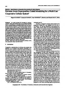
Fig. 6. Measured throughput regions for the TD-based (solid line) and SC-based (dashed line) schedulers, obtained at SNR values of 16dB and 4dB at the near and far users respectively. For each of the operating points uN = 2/3 and uN = 3/4, the SC-based scheduler performs better than the orthogonal scheme.
Consider first, the achievable throughput pairs at operating points u = 0 and u = 1. By appropriate time-sharing, any point on the line connecting these two points is achievable by the TD-based scheduler. Upon employing the SC-based scheduler, the throughput pair (in Mbps) is seen to increase for both users: from [TN ,TF ] = [0.32, 0.1] to [0.39, 0.124] for u = 3/4 and [0.24, 0.113] to [0.297, 0.137] for u = 2/3. The throughput region for the SC-based scheduler is depicted as the convex hull of the achievable throughput pairs, and contains the TD-based scheduler’s throughput region. V. C ONCLUSIONS Superposition Coding is becoming practically realizable thanks to software-defined radios, and throughput gains of up to 25% (over orthogonal schemes) have been measured. Higher throughput gains are achievable when the disparities in the channel qualities of the users’ links is greater, since the users can then trade power and bandwidth to a larger extent. R EFERENCES
−1
PER
10
Near user (TD) Far user (TD) Near user (SC) Far user (SC) −2
10
4
6
8
10
12
14
16
18
20
SNR (dB)
Fig. 5. PER vs. the SNR at that corresponding user for both near and far users. The SC-based scheduler is seen to outperform the TD-based scheduler.
Next, we define the throughput to user i, (i = N, F) to be Ti = wi ρi (1−PERi ), where wi is the fraction of time spent in servicing that user, ρi is the transmission rate, and (1−PERi ), the reliability of the user’s link to the BS. Fig. 6 depicts the achievable throughput region for the TD-based (solid line) and SC-based (dashed line) schedulers, obtained at SNR values of 16dB and 4dB for the near and far users respectively.
[1] D. Tse and P. Viswanath, Fundamentals of Wireless Communication. Cambridge University Press, 2005. [2] T. M. Cover and J. A. Thomas, Elements of Information Theory. Wiley-Interscience, 2006. [3] L. E. Li, R. Alimi, R. Ramjee, J. Shi, Y. Sun, H. Viswanathan, and Y.R. Yang, “Superposition coding for wireless mesh networks,” Proceedings of the 13th Annual ACM International Conference on Mobile Computing and Networking, pp. 330-333, Sept. 2007. [4] A. Zubow, M. Grauel, M. Kurth, and J.P. Redlich, “On uplink superposition coding and multi-user diversity for wireless mesh networks,” 2009 Fifth International Conference on Mobile Ad-hoc and Sensor Networks, pp. 403–411, 2009. [5] D. Halperin, T. Anderson, and D. Wetherall, “Taking the sting out of carrier sense: interference cancellation for wireless LANs,” Proceedings of the 14th ACM International Conference on Mobile Computing and Networking, pp. 339–350, 2008. [6] S. Gollakota, S.D. Perli, and D. Katabi, “Interference alignment and cancellation,” ACM SIGCOMM Computer Communication Review, Vol. 39, No. 4, pp. 159–170, 2009. [7] J. Heiskala and J. Terry, OFDM Wireless LANs: A Theoretical and Practical Guide. Sams, 2001. [8] R. K. Ganti, Z. Gong, M. Haenggi, C.-H. Lee, S. Srinivasa, D. Tisza, S. Vanka, and P. Vizi, “Implementation and Experimental Results of Superposition Coding on Software Radio,” IEEE International Conference on Communications, May 2010.