„17,. _T. _I. 100 K. CLA a ._.î » UIN. n _ „u 0 g __„ FT r lm mm. O FM mM. RW mw.
_ m m L c _ANH .m .v_/v_. um o _ - ___ ,Á. r o 2 _. „___ M u D. M_ I e. e b ___.
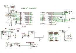
ICSP. +5V. 3x. 2M. _N. M. 8x. 1F. -H. 8.5. 6x. 1F. -H. 8.5. G. N. D. +5. V. 1u. GND.
GND. GND. GND. GND. 1u. G re en. GND. +5V. M. 7. GND. NCP1117ST50T3G.
Mar 30, 2013 - ... testpoints throughout the design. Testpoints will be PTH. POWER SELECTION + DEBUG. Jumpered power sel
from other disciplines to also use this environment. ... SmartPlant Cloud environment. ... The application programming i
software drivers associated with the diagrams and schematics in this handbook.
... The software that implements PSK31 with a Windows PC and soundcard is a
program .... RTS and DTR can be enabled in the interface through the use of
isolating diode(
The query builder enables the engineer or designer to find and create a data view using engineering language rather than
Automated validation when a user replaces symbols in the drawing. ... The application programming interface (API) enable
auxiliary power source. In this ... R. C. ES. ES. 2 3 4. 2 3 4. Transformer. Plug Relay. Boiler Control. P1. Single-zone
She has a blog where she writes about her journey as a single adoptive parent and strives to be real and honest in ....
Bartolini Preamp Schematics The NTBT-918 is a tone control preamp with fully independent Bass and This preamp can be used with either a single 9 volt battery ( 9 volt ...
A bizarre device hidden beneath the village is causing massive earthquakes to repeatedly reform the earth beneath your f
Acoustic Guitar Preamp Schematics The following sound clip demonstrates the preamp on an acoustic guitar first strumming without and then with Protoboard for testing ...
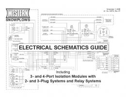
Nov 1, 2008 ... Electrical Schematic – 12-Pin Vehicle Harness – Revision 1–7 . ... Wiring
Diagram – 61185 Park or Turn Harness Kit .........................................89.
Jun 16, 2010 ... schematics are preceded by a Block Diagram for context. The schematics ...
KREF3. Reference oscillator, Tx mixer/Filter, Rx 2nd Mixer. KSYN3.
6. 4. BDC-4. B. A. BDC-3. A. B. SH 2. Model 387 Schematics (03 of 59) ..... CHASS9. S6. S7. 1. HOOD4. 1. HOOD7. 8. HOOD2
Source Abuse Report. Hiniker Plow Wiring Diagram Hiniker Snow Plow. 646 x 789 gif 53kB, 646 x 789 · 53 kB · gif, Western Snow Plow Wiring Diagram.
Nov 1, 2008 ... Electrical Schematic – 3-Plug Straight Blade Snowplows .... Wiring Diagram –
61185 Park or Turn Harness Kit .........................................89.
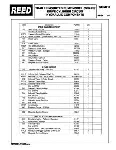
Schematics in this manual show electrical circuit operation ... on each schematic
where the reference designators are ... The component reference designations.
MAINS UNIT F/AR. SPECIFICATI_O§§. 2 inputs: one with multi-pole socket for
Compact Duo and Transicord one normal jack for other instruments or ...
Standard Method For Thinning With The Timberjack 990 Harvester. 1. Start by
felling the strip road, using about 5 m (16 feet) of the loader reach. Delimb the.
This document contains wiring diagrams and component lists for the ... Note that
in this schematic the motor is powered by the .... Arduino Pro Mini 3.3v with.
Schematics for Breakout Examples
This document contains wiring diagrams and component lists for the examples. A diagram may be used for more than one example file. The corresponding files are listed for each diagram.
Getting Started: Hello World /examples/getting_started/hello_world.html /examples/getting_started/hello_world_node.html /examples/processing_js/basic_example.html
Component List
• Button • Led • 10k resistor • 330 ohm resistor
Getting Started: All Examples Use this schematic for all of the examples in /examples/getting_started/
Actuators: DC Motor /examples/actuators/DCmotor.html
Component List
• DC motor • 0.1 uF capacitor • H-bridge SN754410 or equivalent
Note that in this schematic the motor is powered by the Arduino. If you connect anything to the motor you should use an external power supply for the motor. See the schematic on the next page.
Actuators: DC Motor (with external power supply) /examples/actuators/DCmotor.html
Component List
• DC motor • 0.1 uF capacitor • 9V battery & holder • H-bridge SN754410 or equivalent
Make sure your motor is rated at 9V. If it’s lower, use a voltage regulator (such as a LM7805 or adjustable LM317) or use AA batteries in series. Each AA battery you add in series will add 1.2V to 1.5V (depending on the type of battery).
Actuators: RGB Led (Common Cathode) /examples/actuators/rgb_led.html
Check the data sheet for the LED to determine if it is common cathode or common anode. Note: In the rgb_led.html example change COMMON_CATHODE to COMMON_ANODE on line 104.
Actuators: Bi-Color Led (Common Cathode) /examples/actuators/bi_color_led.html
Component List
• Bi-Color led • 2 330 ohm resistors
Check the data sheet for the LED to determine if it is common cathode or common anode.
Actuators: BlinkM RGB Led Module /examples/actuators/blinkM.html
Component List
• BlinkM led module • Button • 10k resistor
Actuators: Stepper Motor (EasyDriver) /examples/actuators/stepper_easydriver.html
Component List
• Bipolar stepper motor • EasyDriver motor driver • DC Power supply for motor
Power your motor with separate DC power supply at the voltage recommended for your particular stepper motor. See this tutorial on bildr.org for more info on using the EasyDriver with Arduino: http://bildr.org/2011/06/easydriver/. EasyDriver website: http://schmalzhaus.com/EasyDriver/.
Actuators: Stepper Motor (4-wire driver) /examples/actuators/stepper_4wire.html
Component List
• Bipolar stepper motor • SN754410NE H-bridge • DC Power supply for motor
Power your motor with separate DC power supply at the voltage recommended for your particular stepper motor. See this tutorial by Tom Igoe for more info on 2 and 4 wire stepper motor circuits for bipolar and unipolar stepper motors: http://www.tigoe.com/pcomp/code/circuits/motors/stepper-motors/.
Actuators: Stepper Motor (2-wire driver) /examples/actuators/stepper_2wire.html
Component List
• Bipolar stepper motor • L293D H-bridge • DC Power supply for motor • 2 10k resistors • 2 1k resistors • 2 NPN transistors
Power your motor with separate DC power supply at the voltage recommended for your particular stepper motor. See this tutorial by Tom Igoe for more info on 2 and 4 wire stepper motor circuits for bipolar and unipolar stepper motors: http://www.tigoe.com/pcomp/code/circuits/motors/stepper-motors/.
Filters: Filtering Analog Input /examples/filters/convolution.html /examples/filters/scaler.html /examples/filters/triggerpoint.html
This schematic is used to test the Teensy 2.0 board with Breakout. The teensy.html example can be used even if you do not have all of these components.
Boards: Arduino Mega /examples/boards/mega.html
Component List
• Arduino Mega • 2 Buttons • 2 10k resistors • 1 Led • 1 330 ohm resistors • Potentiometer • Servo • HMC6352 Compass • BlinkM Led Module
This schematic is used to test the Arduino Mega board with Breakout. The mega.html example can be used even if you do not have all of these components.
This schematic is used to test the Arduino Uno (or similar) board with Breakout. The uno.html example can be used even if you do not have all of these components.
Boards: Arduino Leonardo /examples/boards/leonardo.html Please note: An Arduino Uno R3 is pictured below because the Leonardo board has not yet been added to Fritzing. However the pinout on the Leonardo board is the same as in the illustration below.
This schematic is used to test the Arduino Leonardo board with Breakout. The leonardo.html example can be used even if you do not have all of these components.
Appendix A: Using 3.3v I2C Sensors with a 5v I/O board Although the itg3200 gyro is featured in this schematic, it applies to any I2C sensors that require 3.3v or less.