Available online at www.sciencedirect.com
ScienceDirect Procedia Engineering 96 (2014) 410 – 418
Modelling of Mechanical and Mechatronic Systems MMaMS 2014
Application of computational and design approaches to improve carrier stability Alžbeta Sapietováa*,Vladimír Dekýšb,Milan Sapietac,Peter Pecháčd Department of Applied Mechanics, Faculty of Mechanical Engineering, University of Žilina, Univerzitná 1 010 26 Žilina, Slovak Republic a
[email protected],
[email protected],
[email protected],
[email protected]
Abstract The aim of this paper is to present chosen theoretical and design approaches, which contain evaluation of the usage suitability of mechanical equipment of trolley conveyor of metal chips and its discrete optimization and design modifications. The problem was solved by software MSC ADAMS and original algorithms created in the environment of software Matlab. © 2014Published The Authors. Published byisElsevier Ltd. article under the CC BY-NC-ND license © 2014 by Elsevier Ltd. This an open access Peer-review under responsibility of organizing committee of the Modelling of Mechanical and Mechatronic Systems MMaMS (http://creativecommons.org/licenses/by-nc-nd/3.0/). Peer-review under responsibility of organizing committee of the Modelling of Mechanical and Mechatronic Systems MMaMS 2014 2014. Keywords: mechanism, chips conveyor, optimization, probability, hydraulics, ADAMS, Matlab
Nomenclature f i j n ppoint pα x
objective function number of members of the system including frame class of geometrical constraints, removes exactly j degrees of freedom number of degrees of freedom point estimation of probability confidence interval vector of optimization variables
* Corresponding author. Tel.: +0-000-000-0000 ; fax: +0-000-000-0000 . E-mail address:
[email protected]
1877-7058 © 2014 Published by Elsevier Ltd. This is an open access article under the CC BY-NC-ND license
(http://creativecommons.org/licenses/by-nc-nd/3.0/). Peer-review under responsibility of organizing committee of the Modelling of Mechanical and Mechatronic Systems MMaMS 2014 doi:10.1016/j.proeng.2014.12.110
Alžbeta Sapietová et al. / Procedia Engineering 96 (2014) 410 – 418
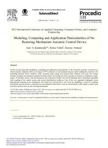
Greek symbols α confidence level n penalization coefficient umax maximal stress ω angular velocity 1. Introduction Designing of lines for machining of bearing rings requires development of a chip conveyor with specific parameters. In a normal belt conveyor the center of gravity of chips is unstable, causing problems with their transport. Therefore chip conveyor carriages were developed to fulfill following requirements: a) to have higher power and an ability to carry particles to larger distances than other transporters are capable, b) to transport not only flexible, long, and turning chips, but with them also larger amount of short and small chips with greater weight per volume unit, c) to work under the floor of the production hall and to be filled by other conveyors or workers according to the operation manual. Already conducted tests and experience show, that if the conveyor is supposed to satisfy given requirements, optimal design parameters have to be chosen. In effort to extend the application of this conveyor in industry, were proposed design modifications, which were preceded by several types of analysis [1]. 2. Function of trolley conveyor of chips The conveyor is designed in a such way, that on the length of 126m 63 trolleys are arranged one by another with carriers on which are attached the rakes (4) (Fig.1). The principle of its operation is based on the chips being pushed by weight of the carrier down to the bottom of the canal (1) and simultaneously moved in the direction of movement of the conveyor. The trolley conveyor is powered by two hydraulic cylinders (7) and (8) via lower (2) and upper rod (3). On the Figure 1 is displayed a carrier with rake in the lowest position, buried in metal chips (6) and the second rake is partially lifted and tearing a pile of metal chips, what indicates that one piece of rake with equipment does not interfere with other rakes and equipment.
Fig. 1 Schematics of the trolley conveyor of metal chips with the hydraulic equipment
Working mode of the conveyor can be divided into four phases: 1. Transportation (Fig.2.a) During transportation of chips in the canal is the lower rod moving by velocity v21. The upper rod is drifted by the lower rod. During motion of the lower rod in the direction of the indicated velocity, is the carrier with rake
411
412
Alžbeta Sapietová et al. / Procedia Engineering 96 (2014) 410 – 418
moved by means of a pivot-groove joint and the carrier is also pulling a trolley (5) connected by a rotational joint. Mobility of the mechanism is for this phase of working mode calculated by formula (1): 券 噺 ぬ岫件 伐 な岻 伐 デ態珍退怠 倹"穴珍 噺 ぬ岫ね 伐 な岻 伐 に ゲ ぬ 伐 な ゲ な 噺 に"経頚繋,
(1)
where 3(i-1) is mobility of a group of free bodies.
y""
V21
5 3 4
V32
2
a
b
y""
V32
V21 c d Fig. 2 Working modes of the conveyor of chips: a) Transportation, b) Lifting of the carrier, c) Displacement of the system, d) Descent of the carrier
2. Lifting of the carrier The next working mode is lifting of the carrier over the transported chips. The lower rod stays stopped. The upper rod continues in motion, presses against the trolley and the carrier is elevated over the transported chips by rotational joint and pivot-groove joint (Fig.2b). During lifting of the carrier the lower rod stands still, i.e. we consider it as a frame, thus in this phase of working mode is the mobility: 券 噺 ぬ岫ね 伐 な岻 伐 に ゲ ぬ 伐 な ゲ に 噺 な"経頚繋 3. Displacement of the system Displacement of the system is done by the upper rod standing still and the lower rod moving backwards, so the system moves back to the start of a working cycle (Fig.2c). 4. Lowering of the carrier Lowering of the carrier to its initial position is done by the upper rod being pulled by the hydraulic cylinder (7) back, while the lower rod is standing still. During this motion a bumper releases the trolley and the carrier returns to the lower position by its own weight. After the carrier descends to the initial position the working cycle repeats. 3. Application of optimization process To achieve proper raking performance of the conveyor, it is essential to properly design the weight of the carrier. If the weight is too small, the contact with transported material is insufficient. If the weight is too large, the large resistance of chips can cause malfunction of the conveyor. The chosen optimization parameters are related to these
413
Alžbeta Sapietová et al. / Procedia Engineering 96 (2014) 410 – 418
facts [2]. As optimization variables were chosen variables that minimize weight of the carrier, without violating the maximal stress constraint (considering fatigue life) [3,4]. According to the experience from previous analyses, the optimization variables were chosen to be the outside diameter D of the carrier and geometrical parameters r and r3 (fig. 3). Then the vector of optimization variables will be: 姉 噺 岷捲怠 "捲態 "捲戴 峅脹 噺 岷経"堅"堅戴 峅脹 ,
(2)
The objective function is the cross-section area of the carrier formed as follows: 繋岫姉岻 噺
for umax
訂ゲ盤帖鉄 貸鳥 鉄 匪 替
35 MPa
繋岫姉岻 噺 膏 ゲ
噺
訂ゲ盤帖鉄 貸鳥 鉄 匪 替
訂ゲ範帖鉄 貸盤待 腿胎ゲ帖鉄 匪飯
and 噺膏ゲ
替
,
訂ゲ範帖鉄 貸盤待 腿胎ゲ帖鉄 匪飯 替
(3)
,
(4)
r
D
for umax > 35 MPa, where the penalization coefficient n is chosen to be 2.
r3
Fig. 4 Stress in the carrier before optimization
Fig. 3 Identification of the optimization variables
The influence of parameters r and r3 on the objective function is “hidden” in the penalization, i.e. these parameters directly affect stress σmax by maximal bending moment (relates to fig. 4) [5]. During selection of starting values there was an effort to increase the value of the dimension of carrier lever from original r = 150mm, as this allows to decrease weight of the working part of the carrier. In the table 1. are results of the optimization process in MATLAB and results of analysis in ADAMS, where flexibility of the carrier is considered. Tab. 1 Evaluation of monitored values in the optimization process Monitored parameter:
X1
X2
X3
Obj. function
Max. stress
[mm]
[mm]
[mm]
f [mm2]
umax [MPa]
Starting values:
50
240
575
536
30,02
Optimal values:
39.5
201,3
550,6
276,5
35
Values calculated in ADAMS:
40
200
557
-
*39,0
414
Alžbeta Sapietová et al. / Procedia Engineering 96 (2014) 410 – 418
* Maximal stress value calculated from model of flexible body of the carrier in the environment of ADAMS/AutoFlex.
Pressure [Pa]
node 13209 Von Mises node 2509 Von Mises node 2712 Von Mises node 13560 Von Mises
Time [s] Fig. 5 Course of stress in chosen nodes in ADAMS
4. Evaluation of the influence of uncertain parameters on the usage suitability of the trolley conveyor In the previous part were all the input parameters deterministic. However as a consequence of manufacturing tolerances, altered (but still acceptable) working conditions and as a consequence of acceptable interventions of a user, we considered variability of chosen parameters. In the first iteration we considered these parameters as random variables with uniform distribution on corresponding interval. Their actual values are (fig. 6): Weight of the rod 芸 樺 極なのど ににど玉軽, Friction coefficient 血怠 樺 極ど な ど に玉, Coefficient of pivotal friction 血椎 樺 極ど どぱ ど な玉, Height of chips 畦 樺 極ぱど ねのど玉兼兼, Volume coefficient of chips 激 樺 極なの ぬど玉, Length of the carrier lever 堅 樺 極なのど にどど玉兼兼, Angle of carrier rotation 砿 樺 極ひど なぬの玉兼兼.
Fig. 6 Load and variable parameters
Alžbeta Sapietová et al. / Procedia Engineering 96 (2014) 410 – 418
415
For the mentioned inputs it is possible to obtain probabilistic description through multiple procedures, starting with analytical relations and ending with simulation methods. To avoid complicated analytical relations and to utilize the illustrative properties of histogram, resp. function of probability density, we chose the Monte Carlo method. In the figure 7 and 8 is the function of probability density of occurrence of the value of force Y3 and friction force from chips X3. Our effort is to minimize the region where Y3 is negative. This can be achieved by narrowing the range of values Q and r, with request of lubrication of f1 and fp and by optimization of the device for specific machining machines in the production hall and possibly by correction of the canal depth.
Reaction Y3 [N]
Malfunction state Y3 < 0
Operating state Y3 > 0
Resistance of chips X3 [N]
Probability [1]
Fig. 7 Relation between resistance X3 and reaction Y3, isoprobabilistic representation
Reaction Y3 [N]
Resistance of chips X3 [N]
Fig. 8 Probability density of occurrence of resistance X3 and reaction Y3
416
Alžbeta Sapietová et al. / Procedia Engineering 96 (2014) 410 – 418
Minimization of region where Y3 is negative, is equal to maximization of probability P, determining the equipment’s ability to fulfill required function (to transport chips in the canal), provided that all components (mechanical, hydraulic, electronic) are in operational state. The mentioned probability will be: 鶏 噺 鶏堅剣決岶桁戴 半 ど岼
(5)
喧椎墜沈津痛 噺 ど ひにぬの 喧待 苔泰 噺 極ど ひにぬ ど ひにね玉
(6)
And based on a simulation we can determine its estimations, [6] – point estimation 喧椎墜沈津痛 and 喧底 (´100.c percent confidence interval). For example for c=0.95
5. Hydraulic device ensuring contact stabilization If the resistance caused by chips rises above acceptable level, the design allows that the carrier begins to rise in order to avoid an overload of the equipment (Fig. 9). While the carrier is elevated, the rake divides the transported material, thus the load is decreased and subsequently the rake descends by its own weight. Whether the pack of transported chips will be completely divided to two separate parts depends on compactness of this pack of chips and of magnitude of the moment acting on them. To prevent an overload or the state when the rake is not in contact with chips, we performed analysis [7].
Fig. 9 Position during load from chips
Fig. 10 Hydraulic device
This paper presents a solution for the presented problem, which was solved by adding a hydraulic device between the trolley and the upper rod (Fig.10 and Fig.11). This particular device serves to press the rake during transport of chips and also serves to free the rake during overload of the conveyor. This ensures that the rake is in constant contact with the transported material [8,9]. The hydraulic cylinder (10) is fixed to the upper rod and the piston with the piston rod is connected to the trolley. Two parallel branches of the hydraulic circuit are leading from the cylinder. In the first branch of the hydraulic circuit is connected the first hydraulic valve (11) and in the second is the second one-way hydraulic valve (12), or the overflow hydraulic valve (13) (Fig.11). To the filling hole of the hydraulic cylinder on the side of a mobile trolley is connected one filling tank (14) with hydraulic fluid. While raking the chips, pressure in the hydraulic cylinder (10) is rising because the load on the carrier is increasing. If the pressure in the one-way hydraulic valve (12) does not exceed maximal pressure pmax, the rake will not rise and will transport chips in given position. If the chips create such strong resistance that the maximal pressure on the one-way hydraulic valve is exceeded, i.e. p1 ≥ pmax, hydraulic fluid starts to flow through the circuit
Alžbeta Sapietová et al. / Procedia Engineering 96 (2014) 410 – 418
to the opposite side of the piston and the rake starts to elevate (Fig. 11). The rake is elevated until the resistance between metal chips and rake does not drop so the rake will separate the chips. After the large pack of chips is divided into several parts, pressure in the cylinder drops below maximal value, the rake descends and by its own mass and pressure in the cylinder pushes the hydraulic fluid to the opposite side of the piston through the first hydraulic valve (11), which has small opening pressure p2 (Fig.12).
Fig. 11 Hydraulic device – lifting of the rake
The maximal travel of the rake during raking is limited by maximal travel of the piston of the hydraulic cylinder of the mobile trolley connected by upper rod. While introducing the device against overload of the trolley conveyor into service, one assembly has to be tested to determine if the hydraulic elements are suitable for transport of given type of metal chips (6) [10]. This test can be done by an overflow valve (13).
Fig. 12 Hydraulic device – lowering of the rake
417
418
Alžbeta Sapietová et al. / Procedia Engineering 96 (2014) 410 – 418
6. Summary In the process of optimization were designed parameters, which minimize mass of the carrier, without violating the stress constraint. The estimation of probability of a case when the Y3 is nonnegative, serves for determination of probability of correct function of the device and together with the determination of probability of failure-free function of components determines reliability of the device (in given time). The used Monte Carlo method can be timeconsuming, but is generally simple to use and the acquired set of data provides opportunities of extensive means of processing and presentation. The device against overload of the trolley conveyor of metal chips can be conveniently used for rake conveyors, which are used mainly in mechanical industry to collect metal chips. After some modifications the conveyor can be used in non-mechanical industry for transport of metal or non-metallic objects. Trolley conveyor with the device against overload is suitable for use in conditions where the risk of overload is present, such as transportation to longer distances or when higher power of conveyor is required. If necessary, the conveyor can be also used for transport over slopes. Mentioned advantages derive from the device against overload, an independent function of individual rakes and the fact that the rakes move over the chips during backward movement.
Acknowledgements This work has been supported by VEGA Agency under No. VEGA 1/1259/12 and VEGA 1/1000/12.
References [1] V. Dekys, A. Sapietova, R. Kocur : On the reliability estimation of the conveyer mechanism using the Monte Carlo method. Machine Dynamics Problems, Volume 30, Number 3, 2006, pp. 58-64. [2] M. Saga, M. Dudinsky, P. Pechac, Optimization of thin shell structures using fsd algorithms in Komunikacie, Vol. 14, No 3, 2012, pp. 32-38. [3] M. Vasko, A. Guran, L. Jakubovičová, P. Kopas, Determination the contact stress depending on the load rate of the NU220 roller bearin, in Komunikacie, Vol. 15, No 2, 2013, pp. 88-94. [4] A. O.Shimanovsky, M. G.Kuznyatsova, Yu. M. Pleskachevskii: The strength analysis of the partitions in road tank reservoirs. In Procedia Engineering, 2012, vol. 48, pp. 607-612. [5] P. Kopas, M. Vaško, M. Handrik, Computational modeling of the microplasticization state in the nodular cast iron, in: Applied Mechanics and Materials, Vol. 474, 2014, pp. 285-290. [6] J. Andel, 1976. Matematická statistika. Praha, SNTL/ALFA. [7] J. Vavro, J. Vavro, jr., A. Vavrova, P. Kovacikova, Dynamic Analysis of Winding Mechanisms for Manufacturing of Raw Tyres. Hutnické listy. 64, (2011), 189-192. [8] M. Saga, P. Kopas, M. Vasko,: Some computational aspects of vehicle shell frames optimization subjected to fatigue life. Communications scientific letters of the University of Žilina, Vol. 12, Nr. 4, 2010, pp. 73-79. [9] M. Zmindak, M. Saga, Structural Optimization of Trusss Structures for Deterministic and Nondeterministic Lodas Using MATLAB. Proceedings of the VII th International Con-ference on Numerical Methods in Continuum Mechanics. High Tatras, (1998), 368-373. [10] P. Novak, M. Zmindak, Z. Pelagic, High-pressure pipelines repaired by steel sleeve and epoxy composition, in: Applied Mechanics and Materials, Vol. 486, 2014, pp. 181-188.