Apr 10, 1998 - On-going Operations: Provide the feature to new subscribers, bill ...... B. Stepien and L. Logrippo, âRepresenting and Verifying Intentions in ...
Chisel
4/10/98
Sculptor with Chisel: Requirements Engineering for Communications Services by Alfred Aho, Sean Gallagher, Nancy Griffeth, Cynthia Schell, and Deborah Swayne 1 Abstract We describe a language called Chisel and an editing tool for Chisel called Sculptor for defining requirements for communications services. The purpose of Sculptor and Chisel is to speed the service creation process by improving communication between organizations, by automating tedious manual work, and by enabling application of formal methods. The design of both the Chisel language and the Sculptor tool was based on user studies, and the initial response from users has been positive. By improving communication between organizations, Chisel potentially benefits every phase of the service creation process.
1. Introduction We have defined a new language called Chisel and an editing tool for Chisel called Sculptor, for defining requirements for communications services and service features. The language Chisel reflects current practice for writing these requirements, because its design originated at a usability workshop involving practitioners. Chisel is unambiguous, it applies to a variety of network technologies, and it has a sound basis for translation to commonly used formal software specification languages. The purpose of Chisel is to improve communication between the diverse people and organizations involved in the telecommunications service creation process. Ideally, the service creation process starts with high-level requirements that are repeatedly refined in subsequent specification and development steps until a correct implementation has been done. However, observations of actual practice indicate that communication may be poor at hand-off points between different organizations.
1
Authors’ contact information: Alfred Aho, Columbia University, New York City; Sean Gallagher, Bellcore, Red Bank, NJ; Nancy Griffeth, Bell Labs, Murray Hill, NJ; Cynthia Schell, Hewlett-Packard, Florham Park, NJ; and Deborah Swayne, AT&T Research Labs, Florham Park, NJ. This work was funded by Bellcore’s SCF3! project, while the authors were at Bellcore.
1
Chisel
4/10/98
As a result, work produced in one step may be incorrectly refined or even ignored and re-done in the next step. We believe that an important part of the solution to this problem must be the use of formal methods to verify the output of one step against its input from the previous step. However, formal methods have rarely been used in the service creation process. This is largely because, currently, the requirements engineers must learn a formal language, they must reverse-engineer the existing systems to define the old features, and they must write the requirements for the new features [38]. This is exceedingly difficult without adequate tools to support the application of formal methods [31]. An alternative to direct application of formal methods is to provide a language for requirements that is natural to practitioners, that eliminates the tedium involved in producing detailed requirements, and that is sufficiently precise to support automated translation to more formal languages. This is what we have tried to do. This work has been motivated by problems in creating service features for the telecommunications network [1, 15, 17, 18, 20, 22], but many similar problems arise for Internet services and the work may be useful in that domain as well. In Section 2, we discuss the particular problems of the service creation process in today’s telecommunications network and explain why a new requirements language is needed. The essence and the difficulty of service creation is determining how to add new functions to the telecommunications network without adversely changing or disrupting existing functions. This can be hard even in a monolithic system. The diverse technology and decentralized operation of the public telecommunications network presents an exquisitely complex challenge to service creators. In Section 3, we define the conceptual basis of our language. A feature is characterized by the set of sequences of events that it enables in the network. We use this characterization to define composition, projection, and other operations on features. Our language permits analyzing composed sets of features for feature interactions and addressing questions such as “Will this feature work on different versions of a system?” or “How do we generate a minimum covering set of acceptance tests?” The language is also simple enough to encourage creation and sharing of feature definitions, which is a prerequisite for analyzing the interworking of features of different vendors. In Section 3.3, we
2
Chisel
4/10/98
describe how feature requirements can be translated to other forms, such as message sequence charts [28] and temporal logic [41]. In Section 4, we discuss how Chisel address many of the problems in the service creation process. In Section 5, we discuss the benefits and limitations of Chisel, we describe its application to solving the feature interaction problem, and we describe some interesting open questions.
2. Background and Motivation 2.1 Business environment Although the process of creating telecommunications services is similar to that for creating any other software, the business and technological environments of today’s telecommunications systems raise some difficult issues. On the one hand, the network is a single universal communications system, providing connectivity between any two people with communications devices. On the other hand, it is maintained and operated by diverse companies using a variety of technologies, some decades old. New technologies are being introduced in the network, such as tone dialing, SS7 (Signaling System 7, a packet-switched network that carries the messages controlling the public voice network), and ISDN (Integrated Services Digital Network, which provides high-bandwidth data channels along with a voice line). However, the scale and decentralized operation of the network require incremental incorporation of new technology. Hence each technology, whether hardware or software, must interwork with a variety of other technologies. Also, the service creation process and the requirements documents will be somewhat different for features implemented on different platforms. Before telecommunications deregulation, features were normally implemented on switching systems, because the switching system vendors were also the communications service providers. After deregulation, service providers cooperated to define a standard platform for implementing new features, called the Intelligent Network (IN) internationally, or the Advanced Intelligent Network (AIN) in North America. An AIN platform is called a Service Creation Point (SCP). This is a computer that uses the IN (or AIN) messages to communicate with a switch about the disposition of a user’s call, according to the IN (or AIN) features active on the call. Call processing features are incremental modifications to the logic that controls call processing. A new 3
Chisel
4/10/98
feature must work correctly for enough subscribers to provide an adequate market for the feature. It must also work correctly in conjunction with the other features of the same subscriber and whatever features other parties to a call may use. Because of the decentralized operation of the network, the service designer may not know what other features will be active on a call. Ironically, the service designer must anticipate that unanticipated new features will be introduced by other service providers. In spite of all these complications, users expect a feature to be as universal as possible, to work the same way regardless of technology or service provider, to be highly available, and to be usable by a subscriber untrained in the communication system. 2.2 Terminology In this section, and again in section 4, we use some terms that we should clarify before starting. First, we use the words “service” and “feature” colloquially, as they are used by service designers. It would be awkward to talk about the "Feature Creation Process" and one rarely hears discussion of "Service Interaction Detection." In the rest of this section and in Sections 4 and 5, we will usually use the term “service” in referring to the process and “feature” in referring to the product of the process. In Section 3, we will introduce a more technical definition of feature, which we use only in that section. We also discuss the role of validation and verification in the service creation process, and we mean them in the sense that Boehm used those terms in [14]. For us, the validation of a feature is checking that the correct feature is being designed, and verification is checking that the feature is being designed correctly. In our description of the software engineering process, we will follow Sommerville’s text on software engineering [42]. He defines three levels of description produced in the requirements engineering process: 1. Requirements definition, stating, “in a natural language plus diagrams, what services a system is expected to provide and the constraints under which it must operate. It is generated using customer-supplied information.” 2. Requirements specification, setting out “the system services in detail. [It is] sometimes called a functional specification, and should be precise. It may serve as a contract between the system 4
Chisel
4/10/98
buyer and software developer.” 3. Software specification, “an abstract description of the software which is a basis for design and implementation.” In this paper, we focus on the use of Chisel and Sculptor for producing the first two kinds of document. Also, we illustrate automatic translation to other forms. Some of these may be necessary or convenient documentation, while others may be initial versions of a software specification. 2.3 The service creation process today Current practice in the process of creating features utilizes a waterfall model. The steps involved in creating a new feature include[27]: 1. Needs Analysis: Determine what market needs a new feature can address 2. Service Description: Create the user-oriented feature requirements definition, and then extend it to create the requirements specification, detailing how network elements (already in the system requirements model) communicate with one another to provide the (new) service. 3. Service Specification: Write the software specification; that is, detailed service logic in individual network elements; verify it against the requirements specification. 4. Service Development: Write or generate code for executing the feature on network platforms. 5.
Service Verification: Verify the feature using integration and acceptance tests.
6.
Service Deployment: Add the feature to the network elements.
7. On-going Operations: Provide the feature to new subscribers, bill existing subscribers, monitor the feature, and provide other continuing functions associated with serving end users. 2.4 Problems in the service creation process Building highly available, usable, multiplatform software requires a good software development process to assure quality even in the best of circumstances. One may well ask whether assurances of quality are remotely feasible when there is no single controlling authority to oversee the software quality process. Assuring quality is especially problematic when features must interwork correctly with all of the technologies, platforms, and other features in the network. 5
Chisel
4/10/98
Bellcore is developing a tool suite called SCF3! (standing for "Service Creation: Form, Fit and Function") to improve the process by automating certain steps in the process and simplifying communication between organizations responsible for the different steps. The problems with current practice are apparent in every phase of service creation. The following list summarizes some observations of the early stages of service creation at several companies and enumerates some of the problems that service creators encounter in practice. 1. Needs Analysis: a) Input: Market studies and currently available features. b) Output: An informal description of a new feature, sometimes as short as one line, prepared for the service designer. c) Current practice: This informal description can come from a variety of sources, such as the marketing organization of the equipment vendor, or a similar organization within the customer’s company. d) Problems: i)
Competing companies naturally do not share their market analyses, so a service designer knows few of the features actively being planned for introduction in the network. Thus competitive pressures can hinder analysis of potential feature interaction problems.
ii)
The communication between marketers and service designers is sometimes disrupted, resulting in development of a different feature from the one requested.
2. Service Description: a) Input: An informal description of a new feature, from marketing. b) Output: A decision on whether it is technically feasible to proceed, and if so, the requirements definition and the requirements specification for the feature. These must cover the call processing, deployment, activation, and interfaces to operations systems. The requirements specification should be validated against the informal description. The requirements specification is normally written in English, with message sequence charts to illustrate the operation of a few of the functions.
6
Chisel
4/10/98
c) Current Practice: A service designer is usually a requirements engineer having extensive network expertise but little programming or computer science background. To design the feature, the service designer first determines how a user interacts with the network to use the feature; that is, she determines what should be the feature’s external interface. The result is a requirements definition for the "user view" of the feature. The requirements definition is usually validated against the information feature description. Next, a possibly different service designer determines how the network elements must communicate to provide the feature. The resulting requirements specification is called the "network view." From the network view, the designer can determine if there is a feasible implementation on a sufficiently representative set of platforms and end-user terminals to reach an adequate market base. The designer also checks if the feature can interwork in a reasonable way with other features that are likely to be present, producing a set of feature interaction requirements. Acceptance tests may be generated. The need for the “network view” as part of the external specification of a feature may seem counterintuitive, but when the customer is a service provider and the product is a feature to run on one box or another in the network, the requirements need to describe the behavior on those interfaces as well as the end-to-end behavior. d) Problems: i)
The network contains many different kinds of network elements. Even for one kind of network element, a variety of technologies may be used. The service designer must filter the relevant information from masses of documents about the network elements. The information overload is even larger than may be immediately apparent, because the service designer must consider not only the standards, but also the vendor implementations, which usually vary somewhat from the standards.
ii)
The documents involved are both numerous and voluminous. Since the divestiture of the local telephone companies by AT&T, Bellcore has documented the generic requirements for the North American telecommunications system. Bellcore's internal catalog lists 2,799 generic requirements documents. there is a single 625-page Bellcore document that describes only the interworking of switch-based features with AIN features. Most Bellcore requirements documents are matched by vendor documents describing what the vendor 7
Chisel
4/10/98 equipment actually does.
iii)
The available documentation of feature requirements is almost always in natural language, interspersed with message sequence charts (MSC’s). At Bellcore, and at other companies, MSC’s are prepared using general-purpose commercial presentation tools, rather than specialized MSC editors, so they cannot be processed easily. Also, the conventions for preparing MSC’s charts are idiosyncratic to a company or even to a specific service designer.
iv)
When the user view and the network view requirements writers are different people, they may duplicate each other’s work on Message Sequence Charts, because most often the designers communicate the requirements entirely in English.
v)
Acceptance tests are not always created; when they are, they are created manually, and their correctness and completeness are taken on faith.
vi)
Analysis of feature interactions is frequently based on personal interpretations of feature behavior. It is impossible to evaluate different methods of analysis because there is no common base of features; even the proposed benchmark [18] is interpreted differently by different researchers.
3. Service Specification a) Input: The user view (requirements definition) and the network view (requirements specification) from the service design step, and the informal description of the feature, from marketing. b) Output: A software specification; that is, detailed service logic, verified against the requirements for consistency and completeness. c) Current practice: Usually, a feature executes on only one network element2. The service specifier uses the requirements specification together with the required functions from the market analysis to define the detailed service logic for the network element with the feature will execute.
2
This is probably a result of both marketing and technical considerations. Usually the company that develops and markets the service is an equipment vendor, and the service is offered as part of the sale of a network element. 8
Chisel
4/10/98
Languages like SDL are used in this step. If appropriate tools are available, it is valuable to verify the service logic against the requirements at this step, ensuring that it is complete and consistent. Software is available for this purpose, including Promela/Spin, StateCharts, and SDL. d) Problems: i)
Most of the input to this step is in natural language and hence ambiguous. The service specifier must resolve any ambiguities, perhaps in consultation with the marketer and the service designer.
ii)
In practice, the software specification is rarely complete enough to permit thorough verification. It may ignore error and exception conditions altogether. In some cases we have seen, the only scenario specified is the "sunny day" scenario; even busy conditions may be ignored. Since the service logic typically executes on a single network element, the verification applies only to the behavior on that network element and not to the end-to-end behavior of the feature.
iii)
The definition of service logic may be repeated in the service development step, especially if the development language uses an entirely different paradigm than the software specification language. If the paradigm changes, the likelihood is that the specification will be translated back to English before being passed on to the development step. For example, Bellcore’s Service Creation Platform, SPACE, provides a graphical language for defining features that is quite different from common specification languages.
iv)
Because specification of detailed service logic is tedious and expensive without producing executable code, it is most frequently not done at all. If automatic generation of code from the software specifications were available for the platforms on which features run and if the generated code were adequately optimized, the verification of specifications would be much more useful in practice.
4. Service Development: a) Input: The requirements specification, from the service design step, and the software specification from the service specification step. The requirements specification is likely to be in English rather than a formal language, and the software specification is likely to be incomplete. 9
Chisel
4/10/98
b) Output: Code and documentation. c) Current practice: The design is usually based on English descriptions of the requirements and logic. Switch-based features are coded in C or in a proprietary vendor language. Since performance is a major issue, higher-level languages are viewed with skepticism. AIN features are usually coded in C or in a proprietary SCP vendor language. d) Problems. i)
Intricate and spaghetti-like code has sometimes resulted from the incremental modifications required by features. Implementation decisions made for one feature may affect its interactions with a new feature, one that was not anticipated when the implementation decision was made.
ii)
The AIN architecture was created to allow more rapid creation of new features, but as more AIN features are added the complexity of introducing new ones increases, thereby slowing their introduction.
iii)
Determining what should be the behavior of a feature in the presence of anomalous behavior elsewhere in the network can be difficult. For example, if an SCP does not respond to a message, should the switch abort the call, continue with normal processing of switchbased features, or follow the feature interaction requirements on the message?
The reader may be skeptical about this description of the service creation process. Can it really be true that natural language is used as late in the process as service specification? It is indeed. Because different individuals with different skills using different tools may be working on each step in the process, every handoff is potentially problematic. At each step, the person doing the work may revert to the natural language description generated at earlier steps, and use that as the starting point for the current work. The handoffs become even more complicated when more than one company is involved. The informal design and some part of the requirements might be written by the customer (a Regional Bell Operating Company, for instance) instead of the vendor, or several operating companies might hire Bellcore to write the requirements.
10
Chisel
4/10/98
2.5 Why a new requirements language? Much excellent research has been done in the area of formal specifications. Our goal is not to add to this work, but to complement it, enabling requirements engineers to use formal methods without having to learn the theory. We agree with Gerard Holzmann in his distinction between requirements and design [31]. Formal description techniques such as Z, SDL, and LOTOS are most appropriate for formalizing an abstract design and for refining the design. Separate correctness requirements are needed, to make statements about the design that can be proved or disproved. Successful creation of correctness requirements in a production environment demands a requirements language that is both precise and natural to the requirements engineers. Since requirements documents often provide several different representations of the requirements, it also demands a tool that simplifies writing requirements in a variety of forms. To define the language for the requirements engineers and to determine the functions of the tool, we held a series of user workshops in 1996 involving requirements engineers and software specifiers. These workshops follow a “user-centered design” methodology developed at Bellcore [21]. The individuals involved in the service creation process stepped through the first three steps of the service creation process for sample features, describing what problems they address and how they solve them, what documents they produce, and what parts of the process are most difficult for them. In later phases of the workshop they brainstormed what improvements they would like to see in the process and what tools they would like to have. The Chisel language and Sculptor editing tool were outgrowths of these workshops. This effort was inspired by prior efforts to apply formal methods to in the service creation process. Yow-Jian Lin developed methods for using logic programming to verify services and detect feature interactions in [19, 35], but his methods were not applied to solving the problem in Bellcore’s service creation efforts because of the time involved for requirements engineers to learn a formal language, to reverse-engineer the existing systems to define the old features, and to write the requirements for the new features [38]. Gerard Holzmann designed and led a successful effort to use formal verification techniques in the design and implementation of part of the SS7 protocol for Lucent’s 5ESS switching system [31]. The work was done by a team of 4-5 developers. In order to fit in the existing design environment, they 11
Chisel
4/10/98
needed to use SDL, which they restricted to make verification possible and extended to express correctness requirements in a language patterned after temporal logic. The work of Holzmann’s team began at the software specification step. A graceful hand-off from the service description step would translate the correctness requirements to an appropriate form – in this case, temporal logic, which is one of the languages to which Sculptor translates Chisel. Luigi Logrippo and his students have used LOTOS to develop powerful formal specification techniques to identify feature interactions in a software specification [24, 25, 43]. In his Ph.D. thesis, M. Faci introduces a method for detecting interactions among features using LOTOS. In the LOTOS specifications, he uses four concurrent processes to define Plain Ordinary Telephone Service (POTS). Because the specification includes an architecture for the execution of the processes, we consider it a software specification rather than a requirements specification. (Other architectural approaches, such as that of Lin [36] and Turner [44], would also be software specifications rather than requirements.) Since there is a natural translation of Chisel requirements to process algebra, and hence to LOTOS, Chisel should be usable in a LOTOS environment as well. We also investigated the use of a language developed by Tadashi Ohta and his colleagues at ATR in Japan. They developed a state-transition rule based specification language STR (for State Transition Rules) and built an impressive collection of complete feature specifications for analysis 34, [ 40]. But like the LOTOS group, Ohta’s addresses the problem of detecting feature interactions in the formal software specifications rather than requirements. Formal definition techniques are most appropriate verifying the properties of the software specification, including feature interaction or non-interaction. Our requirements language has been designed to address several problems that arise in the service creation process that cannot be addressed by formal definition techniques alone: 1. Creating the initial requirements based on the needs analysis. 2. Reverse-engineering the requirements for existing features. 3. Supporting better communication between steps of the service creation process by providing tools that verify the output of each step against the requirements. We have also defined a composition operator for Chisel requirements in order to define feature 12
Chisel
4/10/98
interactions without relying on manual composition of features. A number of authors have noted that the feature interaction problem is usually stated by saying that features behave differently when they have been combined, and the combination is left to the designer. This means that interaction is a product of design choices as well as of the behavior of the features and the preferences of the feature designer. We have defined a composition operation on features to support a more objective approach to the study of feature interactions.
3. The Conceptual Basis of the Language 3.1 Events and event sequences In this section, we will be more precise in our use of the terms service and feature. A feature will be defined as a set of sequences of events that can occur when a feature is active. A service will be defined as a union of two or more features. Chisel is a language for creating the requirements definition and requirements specifications for a feature of a communications network. We consider a communications network to be a collection of subscribers and communicating computers (called network elements) whose behavior includes requesting, providing, and using network connectivity. We have investigated primarily features of the voice telephone network, but we believe that the same ideas can be transferred to video networks and to the Internet. We define a Chisel feature as a set of sequences of events. A feature designer chooses those sequences that capture the essence of the feature’s behavior, where behavior refers to the sequences of messages that subscribers and network elements send to one another and interpret, on receiving them, according to the feature’s function. Thus, the events are messages. We consider a feature to be any function of a reactive system. Representing feature requirements as sequences of events is especially appropriate to a reactive system, because the functions of a reactive system are usually provided as sequences of events (often but not always pairs of requests and responses). An end-user uses and memorizes the sequences for the functions that are important to him. Internally, also, the network elements communicate with one another using sequences of events according to defined protocols. A customer (such as a service provider) for a feature implemented on
13
Chisel
4/10/98
a network element will want requirements stating the sequences of messages sent and received on the network element interfaces. A feature designer focuses on a particular set of network participants (subscribers and network elements) when describing the communication behavior of a feature, in order to reflect a desired viewpoint and level of detail for the feature requirements. The designer may produce several different versions of the requirements, from different viewpoints and at different levels of detail. A set of network participants used in a feature requirements, together with the protocols that are available between them, is called a platform. A feature designer may choose to specify only the “user view” of a call, so that the platform includes only subscribers and a black box representing the network. Requirements for AIN features define the communication among various network elements such as Service Switching Points (SSP’s), Service Control Points (SCP’s), and Intelligent Peripherals (IP’s). All of these network elements are included in the “network view” platform for an AIN feature. Chisel characterizes a feature as the set of event sequences that are essential to the feature’s behavior. The feature designer should include only those sequences whose omission would change the nature of the feature. For example, the behavior of Call Waiting is characterized by event sequences in which a call arrives at a busy telephone. Even though event sequences in which no call arrives at a busy telephone can happen when Call Waiting is active, they are not essential to the definition of Call Waiting. The communication behavior of a feature is restricted by the communication that is possible between the participants in the platform. Each network element originates and recognizes a restricted set of event types. Also, only certain sequences of event types are possible for a given protocol or network element. For example, POTS (Plain Ordinary Telephone Service) allows the messages inTable 1 between a user and a switching system (via a telephone).
14
Chisel User to Switch Off-hook A:Address On-hook A:Address Dial A:Address B:Address Flash A:Address
4/10/98 Switch to User DialTone A:Address Start AudibleRinging A:Address B:Address Start Ringing A:Address B: Address Start CallWaitingTone A: Address B: Address Stop AudibleRinging A:Address B:Address Stop Ringing A:Address B:Address Stop CallWaitingTone A:Address B:Address LineBusyTone A: Address Announce A:Address R:Recording Disconnect A:Address B:Address Display A:Address R:Recording
Table 1. POTS events, based on Bellcore’s Generic Requirements for Switching Systems [6].
The format of an event is: : … : where is an event name, is a symbol, and indicates the type of the parameter. We use types Address (for a telephone number), and Recording (for a set of recordings that can be played back or visually displayed, as on a caller ID box). As illustrated inTable 1, events are messages that are sent by one party to the communication to one or more of the other parties. Most of these events are selfexplanatory, but the event Disconnect A B may be confusing. This event occurs at the subscriberA’s telephone, informing her that the connection has been broken by another party to the active call (subscriber B). The Dial A B event can be defined from a sequence of more primitive events, which we might call Enter A digit. Sequences composed of Enter A digit events may be useful for distinguishing between ordinary numbers, 800 numbers, and feature activation codes. In this paper, as in the current version of Sculptor, we assume that no events are composed of more primitive events. One example of a feature from the telephone network is the function of receiving a call. Table 2 contains several sequences of events from Table 1 that are involved in receiving a call.
15
Chisel
4/10/98
Sequence of Events Start Ringing A B, Off-hook A, Stop Ringing A B, On-hook A
Explanation The telephone rings, a user answers (goes off-hook), and later hangs up (goes on-hook) to terminate the call. Start Ringing A B, Off-hook A, Stop Ringing A B, As above, except that the calling party Disconnect A B, On-hook A disconnects before the called party goes onhook Start Ringing A B, Disconnect A B, Stop Ringing A B The telephone rings and the calling party disconnects before it is answered. Table 2. Sequences of events for receiving a call.
On a telephone that permits only incoming calls, and has no other features, the only sequences that can occur are repetitions of the above three sequences. The sequences in Table 2 use event types, which contain variable symbols taken from a finite set. The event types in a sequence diagram can be turned into events by substituting values from the domain of the variable for the variable throughout the sequence diagram. We use only event types in this paper, and usually refer to them as events rather than event types. In this paper, we will describe only those protocols and network elements for which there is a standard or an implementation. Because the primary purpose of Chiselis to describe communication between disparate systems, perhaps belonging to unrelated organizations, we recommend that all requirements also be restricted in this manner. The service design editor Sculptor, for creating Chisel requirements, actually provides menus of event types for various platforms, such as POTS, the IN and AIN standards IN CS-1, AIN 0.1, AIN 0.2, and AIN 0.x, and the mobile communications standard IS-41, and suggest possible next events as the feature designer prepares the requirements. In Section 3.2, we define Chisel requirements and describe how to specify both platforms and features. In Section 3.2.1, we describe how to define the events and event sequences that are allowed on a given platform. Sculptor can use this definition to limit a feature intended for a POTS telephone to events and event sequences allowed on a POTS telephone and similarly to limit an IN/AIN feature to allowed events and event sequences. In Section 3.2.2, we describe how to use Chisel to define a feature and give an example of a feature definition. In Section3.3, we show how the Chisel feature definitions can be translated to different forms for other kinds of analysis. In Section3.3.4, we define the operations 16
Chisel
4/10/98
of composition and projection on features, and use these in Section 3.5 to make precise the idea of a feature interaction. 3.2 Chisel specifications A Chisel requirements definition or requirements specification consists of a feature name N, a requirements type S, a set P of participants, a set T of event types, and a set of sequences of event types. The requirements types that are discussed in this paper and used in Sculptor are platform and feature. The interpretation of Chisel requirements differs depending on the type of the requirements: Platform requirements specify a set of event sequences that are allowed on the platform, while feature requirements specify a set of event sequences that characterize the feature. Textual expressions describing sequences are relatively hard to create and edit, so we simplify the job of the feature designer by providing a graphical notation in Chisel and Sculptor for describing feature behavior. This notation is called a sequence diagram.
1 Start Ringing B A
2 Off-hook B
8 Disconnect B A
3 Stop Ringing B A
6 On-hook B
7 Disconnect B A
9 Stop Ringing B A
4 Disconnect B A
5 On-hook B
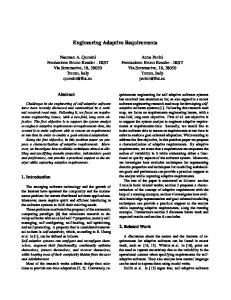
Figure 1. Tree Diagram for Receiving a Call This graphical notation was adapted from the current practice of requirements engineers. It was elicited at a series of workshops in which we observed their practices in creating the feature requirements. In current practice, a requirements engineer defines the sequences of event types for a feature using a picture called a “tree diagram.” The tree diagram gives the possible choices of next 17
Chisel
4/10/98
event as children of the preceding event. The tree diagram for the sequences of events involved in receiving a call is given inFigure 1. By convention, the set of sequences corresponding to a tree diagram are those that begin at designated start events and end at designated finish events. To encourage conciseness in the diagrams, it is useful to permit branching when identical subgraphs appear at multiple places in the same diagram. Thus we permit branching, including loops, and hence we allow arbitrary graphs. For this reason, we call the diagrams “sequence diagrams” instead of “tree diagrams.” For those familiar with process algebra, a sequence diagram corresponds to a process graph of a regular process, using trace semantics. This correspondence is discussed in more detail in Section 3.3.4. Let T be the set of event types for a Chisel sequence diagram. We assume that the parameters of the events taken on values over finite sets, so that the set of event types is finite. Since events are messages between participants in the platform, we define attributes sender(e) and receivers(e) for each event e. All of the senders and receivers should be participants in the platform, that is, for each event e belonging to T, sender(e) is in participant in P and receivers(e) is a subset of the participants in P. A sequence diagram has four components: V, VS, VF, and E. 1. V is a set of typed, labeled vertices. Each vertex v belonging to V has attributes type(v) and label(v). The sequences of events that characterize a feature are constructed from event types, so type(v) belongs to T. The label label(v) of a vertex is used only to identify the vertex. The labels do not appear in the sequences of events. 2. VS " V is the set of start events in the sequence diagram. 3. VF " V is the set of finish events. 4. E " V × V is a set of directed edges. In Figure 1, VS = {1} and VF = {3,5,6}. In many cases, nodes of VS will not be root nodes of a sequence diagram and nodes of VF will not be leaf nodes, so these sets must be defined.
18
Chisel
4/10/98
The set of sequences generated by a sequence diagram is the set of sequences of event types encountered when following paths of the diagram from a start vertex to a finish vertex. To simplify drawing certain sequence diagrams, we assume that T contains an event type noevent, which is ignored when constructing event sequences. Thus the sequence a, noevent, b is the same as the sequence a, b. To include an empty sequence in the set of event sequences represented by a sequence diagram, include a vertex with event type noevent as both a start and a finish vertex. 3.2.1 Defining Platforms Using Chisel A Chisel specification of type platform defines not only the event types allowed on the platform, but also the sequences that are allowed on the platform. For example, using a plain, ordinary telephone (POTS), user-originated events Off-hook and On-hook must alternate. Start Ringing should never happen unless the user telephone is on-hook and Stop Ringing must happen immediately after it goes off-hook, to avoid dangerously loud sounds in a user’s ear. These are the only hard and fast rules concerning a POTS telephone. Because the POTS platform is so simple and non-restrictive, it is not especially interesting and we do not show the sequence diagram here. The sequence diagram for an IN or AIN platform is much more interesting since it is more restrictive. It specifies the allowed communication behavior among Service Switching Points (SSP’s), Service Control Points (SCP’s), and Intelligent Peripherals (IP’s). This behavior is specified in the various AIN Generic Requirements documents, and is far more complicated than POTS. We gave a brief, simplified description of AIN here. Features running on an AIN platform can modify the normal switch-based processing of a subscriber’s call. In order for an AIN feature to be used, the switch must be compliant with the AIN requirements. These requirements define a state machine and a set of input and output messages and their parameters [7, 8]. The messages include the usual messages between a user and a switch. They also include a collection of messages between a switch and an SCP. The following table gives a simplified version of some of these messages:
19
Chisel
4/10/98
Switch to SCP Trigger N:TriggerName S:Address A:Address B:Address Resource S:Address A:Address R:Recording SCP to Switch Response R:ResponseType S:Address A:Address … (see below) Table 3. Switch/SCP messages.
The format of the above message definitions is : … . The type TriggerName is an enumeration of the names of IN triggers. Some valid TriggerName’s are ORIGINATION_ATTEMPT, INFO_COLLECTED, INFO_ANALYZED, and NETWORK_BUSY. In the trigger message, the first address parameter is that of the subscriber, the second of the calling party, and the third of the called party. The type ResponseType is an enumeration of the SCP responses to trigger messages. Some valid ResponseType’s are ANALYZE_ROUTE, CONTINUE, FORWARD_CALL, and SEND_TO_RESOURCE.
The Resource S A D message responds to the
SEND_TO_RESOURCE message. The string D is a string of collected digits. Additional parameters (after the subscriber and calling party addresses) for the ResponseTypes are given in the following table. Response Type ANALYZE_ROUTE FORWARD_CALL CONTINUE SEND_TO_RESOURCE DISCONNECT
Additional Parameters B:Address C:Address B:Address C:Address B:Address R:Recording
Table 4. Parameters for response messages. ANALYZE_ROUTE S A B C means to route a call from A to B with C as the paying party (normally, C will be A). S is the subscriber on whose behalf the trigger was activated, usually A or B. FORWARD_CALL S A B C means to forward a call to C, originated by A, with terminating address B. CONTINUE S A B means to continue processing the call as if no trigger had occurred. SEND_TO_RESOURCE S A R means to play the recording R at address A and collect the response (if any). DISCONNECT S A means to terminate processing of calls from A until after A has gone onhook. 20
Chisel
4/10/98
Error! Reference source not found. gives a simplified version of the sequence diagram for the AIN model, as defined in GR-CORE-1298. Only two of the possible triggers are included. The other triggers would add more event types following the event types shown, but the sequences of events are quite similar for each trigger. 1 Off-hook A
2 Trigger ORIGINATION_ATTEMPT S A B
10 DialTone A
11 Dial A B
12 Trigger INFO_COLLECTED S A B
25 noevent
3 Fesponse SEND_TO_RESOURCE S A R
4 Announce A R
13 Response ANALYZE_ROUTE S A X Y
8 Response DISCONNECT S A
9 On-hook A
14 LineBusyTone A
5 Dial A D
15 On-hook A
6 Resource S A D
16 Start AudibleRinging A X
17 On-hook A
18 Stop AudibleRinging A X
19 Stop AudibleRinging A X
20 On-hook A
21 Disconnect A B
22 Disconnect A B
23 On-hook A
Figure 2. A simplified sequence diagram for the AIN platform, with triggers ORIGINATION_ATTEMPT and INFO_COLLECTED. Switch processing is potentially interrupted by the two triggers. The responses from the SCP are the same for both of these triggers (although some other triggers have different responses). It is also possible that neither trigger is used.
21
Chisel
4/10/98
The current version of Sculptor contains the platform rules for various versions of AIN, one version of IN, and the wireless communication standard IS-41. Sculptor discourages a service designer from creating feature requirements that are not in the allowed set for the relevant platform (but doesn’t prevent it altogether). It does this by providing a menu of possible next events after each event has been placed in the sequence diagram. In order to add other sequences, the feature designer must edit the sequence diagram without Sculptor support. 3.2.2 Defining Features Using Chisel A Chisel specification of type feature means that the feature can be considered implemented on a platform only if all of the specified sequences of events can be executed on the platform. That is, a subscriber can use any of the event sequences defined by the sequence diagram. The platform need not be stated explicitly as part of the feature requirements, because a simple test can be used to determine if a feature can be used on a given platform. A feature using event types T and specified by sequence diagram G is allowed on a platform providing event types T’ and specified by sequence diagram G’ if T " T’ and every sequence of event types generated by G is also generated by G’. Feature Example (Call Waiting). The Bellcore Feature Specification Document for Call Waiting says (in part) that “Call Waiting is a feature whereby a line in the talking state is alerted by a call waiting tone when another call is attempting to complete to that line. ... The feature also provides a hold feature that is activated by a switch-hook flash. Consecutive flashes allow the customer (with the feature activated) to alternately talk to the original and the new calling party.” There are many more pages of requirements, but this particular requirement states that the Call Waiting feature recognizes the call-waiting events Start CallWaitingTone m n and Stop CallWaitingTone m n and the event Flash m in addition to the more usual POTS events. Also, Call Waiting must provide, among others, the following characterizing sequence of events: Off-hook m, Dialtone m, Dial m n, Start AudibleRinging m n, Stop AudibleRinging m n, Start CallWaitingTone m q, Flash m, Flash m, Flash m, Disconnect m q, Flash m, Disconnect m n, On-hook m 22
Chisel
4/10/98
Additional sequences are needed to characterize Call Waiting. The user view sequence diagram including the most common Call Waiting sequences is given inFigure 3. 1 Off-hook A
17 Disconnect A C
18 Stop CallWaitingTone A C
21 On-hook A
19 Disconnect A B
20 On-hook A
22 Disconnect A B
A
23 Disconnect A B
2 DialTone A
24 On-hook A
3 Dial A B
25 Stop CallWaitingTone A C
4 Start AudibleRinging A B
26 On-hook A
5 Stop AudibleRinging A B
27 Start Ringing A C
6 Start CallWaitingTone A C
28 Off-hook A
7 Flash A
8 Stop CallWaitingTone A C
9 Flash A
29 Disconnect A C
31 On-hook A
30 On-hook A
32 Disconnect A C
B
33 On-hook A
10 Flash A
341 Start Ringing A B
11 Disconnect A C
40 Disconnect A B
35 Off-hook A
12 Flash A
41 Flash A
36 Disconnect A B
37 On-hook A
13 Disconnect A B
15 On-hook A
42 Disconnect A C
44 On-hook A
38 On-hook A
39 Disconnect A B
14 On-hook A
16 Disconnect A B
43 On-hook A
45 Disconnect A C
C
D
Figure 3. A sequence diagram for the most common Call Waiting sequences. 23
E
Chisel
4/10/98
The start and finish vertices in Figure 3 are VS = { 1}, V F = { 20, 22, 30, 32, 38, 39, 14, 16, 43, 45 }. The “expected” Call Waiting scenario, in which a call arrives to a busy line and the Call Waiting subscriber switches back and forth, is in the top center of the diagram. The subdiagram A applies if the second call hangs up immediately. Subdiagram B or C applies if the subscriber hangs up while a party is on hold. All of the features described so far have been based on a “user view” platform between a single user and the network. 1 Off-hook A
2 DialTone A
3 Dial A B
4 Start AudibleRinging A B ||| Start Ringing B A
5 Off-hook B
16 On-hook A
14 Disconnect B A ||| Stop AudibleRinging A B ||| Stop Ringing B A
7 On-hook A
10 On-hook B
8 Disconnect B A
11 Disconnect A B
9 On-hook B
15 LineBusyTone A
13 On-hook A
6 Stop AudibleRinging A B ||| Stop Ringing B A
17 On-hook A
12 On-hook A
Figure 4. Two-party POTS sequence diagram. In this diagram, we use a shorthand notation E|||F for events that occur in succession, in either order EF or FE.
24
Chisel
4/10/98
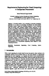
We can also combine the views of the originating and terminating ends of the call to specify the impact of features on the communication behavior of both parties to the call. This platform includes the two subscribers and the network. Here is a characterizing sequence of the basic POTS call service between two parties: Off-hook m, Dialtone m, Dial m n, Start AudibleRinging m n, Start Ringing n m, Off-hook n, Stop Ringing n m, Stop AudibleRinging m n On-hook n, Disconnect m n, On-hook m A complete sequence diagram for the two-party version of POTS is given inFigure 4. We illustrate the Sculptor on-screen notation for an AIN feature in Figure 5. The feature is Originating Call Screening, which requires the telephone user to enter a PIN before being allowed to originate calls to screened numbers from the subscriber’s telephone. The network view presented inFigure 5 specifies the effect of this feature on the communication behavior of the SSP, SCP, and IP. The Sculptor representation adds some visual cues to make it easier to distinguish which network elements are involved. It uses an ellipse to represent an SSP, a triangle an SCP, and a square an IP. A message from one network element to another is represented by drawing the symbol for the sender on top of the symbol for the receiver. The symbol for the receiver is offset up and to the right. After the user has dialed, the SSP processing is interrupted and a trigger message, INFO_COLLECTED, is sent to the SCP. The SCP processes the trigger message by checking whether the dialed number is allowed. If it is, the SCP tells the SSP to route the call (ANALYZE_ROUTE). If not, the SCP gives the user an opportunity to enter a PIN to over-ride the Originating Call Screening (SEND_TO_RESOURCE). If the PIN is correct, the SCP will tell the SSP to route the call; otherwise, it will tell the SSP to disconnect it.
25
Chisel
4/10/98
1 Off-hook A
2 DialTone A
3 Dial A B
4 Trigger INFO_COLLECTED A A B
5 Response ANALYZE_ROUTE A A B
8 Response SEND_TO_RESOURCE A A R
7 LineBusyTone A
6 Start AudibleRinging A B
9 Announce A R
10 Dial A N
11 Resource A A N
12 Response DISCONNECT A A
13 On-hook A
Figure 5. AIN Feature Originating Call Screening 3.3 Translation to and from other forms 3.3.1 Message sequence charts. When designing a new feature, today’s feature designers produce several message sequence charts, 26
Chisel
4/10/98
also called call flow diagrams or call flows. The call flow has a vertical bar (a fence post) corresponding to each network element participating in the platform. The arrows between fence posts represent messages. If a path can be drawn from the head of an arrow downward through the chart to the tail of another, then the first message precedes the second one. Figure 6 illustrates how to generate a message sequence chart from the selected path in a sequence diagram of Figure 5 (the edges of the selected path are emboldened). As mentioned in Section 2.4, feature designers typically produce at least the call flow for the “sunny day scenario.” They also generate several call flows describing exception and error scenarios. Each one of these scenarios represents a single path, from root to leaf, in the sequence diagram. Sculptor automatically generates call flows between two user-selected vertices of a sequence diagram. If there are multiple paths, Sculptor selects a shortest path and generates the call flow corresponding to that path. If there is more than one start vertex, the feature designer must designate the start vertex as well. A feature designer may designate a path other than the shortest one by selecting more vertices. The path used will be the shortest path including all of the vertices.
SSP
SCP
Off-hook A DialTone A Dial A B Trigger INFO_COLLECTED A A B Response SEND_TO_RESOURCE A A R Announce A R Dial A N Resource A A N Response DISCONNECT A A N On-hook A
Figure 6. Converting a selected sequence from the sequence diagram in Figure 5 to a message sequence chart 27
Chisel
4/10/98
Temporal logic statements can be derived from message sequence diagrams. An algorithm for this purpose can be found in [35]. Temporal logic statements are used in the SCF3 tool suite to validate a detailed software specification against the requirements specification, using SPIN 30]. [ 3.3.2 Text. Sculptor also generates a textual representation of a sequence diagram in a modified outline format. The textual representation has two key advantages: First, it is easy to share among people who have differing computing hardware and software. Second, it is considerably terser than the corresponding sequence diagram, requiring less than half the paper to print a readable and complete requirement.
1: Switch: Start Ringing B A 1.1: User: Off-hook B User: Stop Ringing B A 1.1.1: Switch: Disconnect B A User: On-hook A 1.1.2: User: On-hook A 1.2: Switch: Stop Ringing A B
Figure 7. Textual form of the sequence diagram for receiving a call, from Figure 1. To produce the textual form, the sequence diagram is traversed recursively, using a depth-first search [2], and vertices are listed in the order in which they are encountered, so all the vertices in the subgraph below vertex 1 are listed before those below vertex 2. Vertices with siblings have labels and all children of the same parent are indented the same amount. A vertex that is an only child is listed directly beneath its parent; it is not indented. Our sequence diagrams are frequently graphs rather than trees, so we have to be able to account for cycles and branches. In the modified outline format, any vertex which has multiple parent vertices is also labeled, and all parent vertices encountered after the first one are described by adding a ’Goto ...’ line to the outline. The textual form of the Call Waiting sequence diagram given inFigure 3 is illustrated in Figure 8.
28
Chisel
4/10/98
Service designers can edit the text rather than the sequence diagram. Turning the text back into a graph is a difficult problem, so we manage it in two stages: First, we strip all the "Goto’s" from the text form, giving a spanning tree of the sequence diagram. We can then use any one of the many algorithms for drawing trees (Walker 1990), and redraw the additional edges afterwards.
1:
User: Off-hook A Switch: DialTone A User: Dial A B Switch: Start AudibleRinging A B Switch: Stop AudibleRinging A B 1A: Switch: Start CallWaitingTone A C 1.1:
1.2:
User: On-hook A Switch: Stop CallWaitingTone A C Switch: Ringing A B User: Off-hook A 1.1.1:
Go to 1A
1.1.2:
User: On-hook A
1.1.3:
Switch: Disconnect Go to 1.1.2
User: Flash A Switch: Stop CallWaitingTone A C 1.2.2:
User: Flash A 1.2.2.1:
Switch: Disconnect A B User: Flash A 1.2.2.1.1: Go to 1A 1.2.2.1.2: Switch: Disconnect A C Go to 1.2.2.1.3 1.2.2.1.3: User: On-hook A
1.2.2.2:
User: Flash A 1.2.2.2.1: Go to 1.2.2 1.2.2.2.2: Switch: Disconnect A C User: Flash A 1.2.2.2.2.1: Switch: Disconnect A B Go to 1.2.2.2.2.2 1.2.2.2.2.2: User: On-hook A 1.2.2.2.2.3: Go to 1A
1.3 Switch: Disconnect A C Switch: Stop CallWaitingTone A C Go to 1A
Figure 8. Textual form of Call Waiting requirement
3.3.3 Transforming sequence diagrams to finite state automata and regular expressions In this section we describe how to define a state machine recognizing the same sequences as are specified by a Chisel sequence diagram. We define the state machine by defining a state corresponding 29
Chisel
4/10/98
to each path in the sequence diagram beginning at a start vertex. We also define a state corresponding to the empty path. For each sequence of event types along such a path, the transition on event e takes state s to state se. Figure 9 illustrates this translation, using the sequence diagram fromFigure 1. Table 5 summarizes the transitions of the finite state machine. 0 empty
1 Ringing
2 Offhook
4 Disconnect
Ringing
3 Disconnect
5 Onhook
1 R
Offhook
Disconnect
4 R Off D 6 Onhook
Offhook, Onhook, Disconnect
2 R Off
Onhook Ringing
Ringing Offhook
Offhook Ringing Disconnect
Disconnect
3 RD
Onhook Offhook Ringing Disconnect
Onhook
5 R Off On
Offhook Onhook Ringing Disconnect
Onhook
6 R Off D On
Offhook, Onhook, Ringing, Disconnect
7 error
Figure 9. Translation from a sequence diagram (left)to a state machine (right). Event types are abbreviated in the state machine: R=Ringing, Off=Off-hook, On=On-hook, D=Disconnect. State 0 is the empty state. State i corresponds to the sequence of event types defined by a path terminating at vertex i. The transitions of the finite state machine simulate a traversal of the sequence diagram from a start vertex to a final vertex. Thus the set of sequences of events accepted by the finite state machine is the set generated by the sequence diagram. From the finite state machine, we can compute the regular expression for the set of sequences of event types. Regular expressions (and hence also finite state machines) can be converted to sequence diagrams using a construction very similar to that given on pp 122—124 of [2]. 30
Chisel
4/10/98
Old State
Event
New State
Condition
s
e
se
If a vertex corresponding to s has a child with event type e
s
e
error
No vertex corresponding to s has a child with event type e
error
e
error
always
empty
e
e
If e is the event type of a start vertex
empty
e
e
If no start vertex has event type e
Table 5. Defining transitions of a finite state machine from a sequence diagram 3.3.4 Defining a process algebra expression from a sequence diagram Process algebra provides a algebraic framework for the problem of concurrent communicating processes[29, 39]. We will show in this section that Chisel maps naturally to a process algebra. Since Chisel does not deal at all well with concurrency, the mapping to process algebra may be a good way to address this limitation. Using process algebra, we can also permit infinite sets of events. The definitions we use here are based on Baeten’s text on process algebra [4]. A Basic Process Algebra (BPA) is defined by its signature and its axioms. The signature consists of constants and the operators used to form expressions. For Chisel, the constants are the event types and the operators are sequencing and non-deterministic choice. The operators as they appear in sequence diagrams are shown in Figure 10. In LOTOS, (a) would be written E;F, (b) would be written E[]F, and (c) would be written E;(F[]G) [45]. The axioms of basic process algebra are: E[]F = F[]E E[](F[]G) = (E[]F)[]G E[]E = E (E[]F);G = E;G[]F;G (E;F);G = E;(F;G) Since with trace semantics, processes are equal if they have the same traces, we add the axiom: 31
Chisel
4/10/98 E;(F[]G) = E;F[]E;G
E
E
E
F
F (a)
G
F (b)
(c)
Figure 10. (a) Sequential composition (E followed by F); (b) Non-deterministic choice (E or F); (c) E followed by either F or G
With just the first five axioms, above, two expressions that represent the same process are said to be bisimilar, and the algebra is said to have bisimulation semantics. To understand the difference between trace and bisimulation semantics, consider the difference between the caller and called party in setting up a call. After the caller dials (the event Dial A B), the next event is either AudibleRinging A B or LineBusyTone A. The caller has no control over which event happens next. This corresponds to the expression Dial A B ; AudibleRinging A B [] Dial A B; LineBusyTone A . In contrast, the called party does make the choice of which event occurs next. (This choice is independent of the idle or busy state of the called side – consider the Make Busy feature and the Call Waiting feature.) From the called side, the expression would be Dial A B ; (AudibleRinging A B []LineBusyTone A) . Because of the difference in choice points, the two expressions are not equal. We have been using trace semantics for sequence diagrams because the requirements engineers treat each feature as a single process, regardless of the number of parties to the call or the number of “black box” network elements involved. Trace semantics seems to provide the most faithful reflection of 32
Chisel
4/10/98
their verbal description of their reasoning process as they create their tree diagrams. However, concurrency is implicit in communications systems. This concurrency is implicitly recognized in the sequence diagrams, since each event involves a sender and one or more receivers. We leave it to future work to determine how to decompose the monolithic requirements of the sequence diagrams into a collection of requirements for concurrent processes. 3.4 Operations on Sequence Diagrams In this section, we define two operations for combining sequence diagrams (union and extension) and one operation for focusing on a restricted view of a sequence diagram (projection). To motivate the operations, we consider how features execute. Our model of feature execution is that the feature executes on a network element. A stream of messages arrives at the network element from other network elements. The arrival of each message is an event at the receiving network element. It processes the message and may respond, sending one or more messages back to the other network elements. A feature processes every event that belongs to an event type that it recognizes. If the Chisel specification has set T of event type, then the feature processes all incoming events that belong to T and may generate outgoing events, which must also belong to T. Thus the sequence of events visible to the feature can be constructed from its sequence diagram using a projection operation. Projection: The projection #E(s) of a sequence s onto a set of event types E is the maximal subsequence of s such that all events in s belong to E. The projection of a set of sequences S onto a set of event types E is the set { #E(s) | s belongs to S }. When projecting onto the event types associated with a specific feature, we will writeevents(F) for the set of event types of feature F. The projection operation is useful for describing a specific view of a feature. For example, a one-sided user view for POTS can be obtained from the two-sided view in Figure 4 by projecting the sequence diagram for POTS onto the terminating-side event types. It’s easy to see that the projection onto the terminating side event types Ringing n m, On-hook n, Off-hook n, and Disconnect n m gives the same sequence diagram as Figure 1 for receiving a call.
33
Chisel
4/10/98
The union operation describes the combined behavior of two features, as defined by their sequence diagrams. The set of event sequences in a Chisel specification must all be available to a subscriber in any implementation of the feature. In this spirit, we say that we have implemented both features of a subscriber if a subscriber can use all of the sequences characterizing either of the features. Union: Let LF be the set of sequences characterizing feature F and LG be the set of sequences characterizing feature G. Then the union F $ G of features F and G is characterized by the set of sequences LF $ LG. Union is the set union of the sets of event sequences, so that the requirements of the union of the features is the union of the requirements. Feature extension provides a shorthand for re-use of parts of the sequence diagram from other features. Feature F extends feature G when it behaves just like G until it is invoked or initiated by some event, after which the behavior modifiesG’s behavior. F may also return to the strict behavior of G. Extension: If G is a sequence diagram with one entry vertex and one exit vertex and if the sequence diagram F has a subgraph H with one entry vertex and one exit vertex, then we can extend F by replacing the subgraph H with G, and possibly augmenting F’s start and finish vertex sets with vertices from G. [See attached drawings, figures 11a and 11b.] Figure 11. Extension of POTS with Call Waiting. The subgraph of the POTS sequence diagram (left) containing vertices 7, 8, and 9 can be replaced by the Call Waiting sequence diagram with entry vertex 15 and exit vertex 28. Figure 11 illustrates the use of extension to abbreviate the Call Waiting sequence diagram. We permit insertion of vertices having event type noevent (vertices 7 and 9). These vertices simplify constructing a subgraph with only one entry and one exit point. 3.5 Feature Interactions Researchers on feature interactions agree on an informal definition of feature interaction, that a feature interaction occurs between two features if one feature changes the behavior of the other. We use the union and projection operations to formalize that notion here. We say that one feature changes the 34
Chisel
4/10/98
behavior of the other if, after projecting the sequences in the combined requirement (the union of the two sets of event sequences) onto the event types recognized by one of the features, the resulting set of sequences is different from the original set of sequences for the feature Feature Interaction: Given a feature F characterized by the set of event type sequences LF and the feature G characterized by the set of event type sequences LG, if #events(F)(LF $ LG) % LF or #events(G) (LF $ LF) % LG, then there is a feature interaction between F and G. We can be a little more specific. If a sequences is in LF and #events(G) (s) is not in LG, then feature G can observe a sequence of events when F is active that it may not be able to process. As a consequence, additional requirements are needed for G’s behavior when F is active. Feature interactions slow the service creation process considerably. In practice, when two features do interact, it is necessary to create extra requirements explaining how the two features behave in combination. Also, the software specifications and the code need to be altered for the case that both features are active. If features do not interact, a simple joint recognizer can be implemented by running the individual recognizers in parallel. Thus if two features do not interact, they can be used without modification on the same call. Discovering a large number of feature interactions in the Service Description phase may be reason for reconsidering development of a new feature. Feature Interaction Example (Three-Way Calling and Call Waiting). The primary cause of interactions between Three-Way Calling and Call Waiting is use of the same event Flash) ( for different purposes by the two features. Once the Flash event has been used, the sequences possible for the two features diverge. The following sequence illustrates a Call Waiting sequence whose projection is not a Three-Way Calling sequence. The emboldened events are recognized by both features and the italic events are recognized only by Call Waiting. Ringing m n, Off-hook m, CallWaitingTone m q 1, Flash m, Disconnect m n, On-hook m In this situation, after Flash, Three-Way Calling would provide Dialtone. Conversely, the following Three-Way Calling sequence does not project onto any valid Call Waiting sequence:
35
Chisel
4/10/98 Ringing m n, Off-hook m, Flash m, Dialtone m, Dial m q, LineBusyTone m, Flash m, Disconnect m n, On-hook m
After the second Flash event, Three-Way Calling returns the subscriber to the original call, which is eventually disconnected. But Call Waiting would giveDialtone again after the second Flash. Bergstra and Bouma [11] have defined features using interworkings, which are quite similar to message sequence charts. A feature interaction occurs if the interworkings representing two features do not have a consistent merge. Our definition of feature interaction reduces to this if each feature is defined by only one sequence of events. It is not clear what Bergstra and Bouma’s composition operation is if each feature consists of several interworkings. Our definition says that features interwork (do not interact) if there is a single consistent interworking merge of the features. Another interesting issue, which we leave to future work, involves generalizing the definition of feature interaction to use bisimilarity instead of trace equality. Unfortunately, absence of feature interactions in the “user view” means only that it is possible to implement the features interactions. If an implementation has already been chosen for one feature that will interact with any reasonable way of implementing the second feature, then feature interactions will still occur. The practice, at present, is to define requirements for these feature interactions also. For example, current implementations of the switch-based Repeat Call feature cannot be used after dialing an 800 number, because it is implemented by monitoring the number for busy, and it cannot do this with 800 numbers. Obviously, other ways of implementing Repeat Call (for example, re-processing the call from the point at which the switch collected the digits) would work.
4. Using Chisel in the Service Creation Process The importance of Chisel in the service creation process is that it provides a simple method for capturing the essential behavior of a service. As in the automation of many tasks, the hardest part is not developing the algorithms or doing the computations. Instead, the hardest part is capturing correct and unambiguous input at a reasonable cost. Using Chisel, Sculptor provides a simple tool that automates tasks currently done manually by requirements engineers (drawing sequence diagrams and message sequence charts). By automating the tasks, it aims to make them less tedious. In addition, it reduces the number of errors by assuring 36
Chisel
4/10/98
that the events used are part of the protocol and that the message sequence charts are consistent with each other and with the sequence diagram. Finally, the generated requirements are unambiguous. Defining feature requirements using Chisel and Sculptor supports better integration of the service development process steps and simplifies validation of a feature in its various forms throughout the service creation process. Here we detail some of the benefits that Chisel and Sculptor can provide at each step of the service creation process. (The problem descriptions that follow are very terse summaries of the descriptions in Section 2.) 1. Needs Analysis Problems. i)
Problem: Competitive pressure hinders analysis of feature interactions. Contribution: Existing service features are easy and inexpensive to model with Sculptor, just by observing their actual behavior. We hope that this will encourage sharing of requirements for existing features in order to improve interoperation of network features. We recognize, however, that planning information is unlikely to be shared.
ii) Problem: Communication is disrupted at each handoff. Contribution: Visualization and simulation tools can be developed for features defined in Chisel, since they are easy to translate to other forms. Such tools can encourage dialog between requirements engineers and marketers, to check that the requirements describe the intended feature accurately. Some forms of usability testing are also possible based on Chisel requirements. 2. Service Description Problems. i)
Problem: Designers must deal with documentation for a myriad of network elements, technologies, and vendor implementations. Contribution: Chisel supports automated techniques for restricting a requirement to available events, as illustrated by the tool Sculptor. The tool provides menus of the available events for each message between a pair of network elements. Which events are available can depend not only on the messages defined on the platform, but on more specific rules such as those for AIN messages and responses. Sculptor currently contains the rules for AIN 0.1, AIN 0.2, AIN 0.x, and IN, among others reducing the level of expertise and the need for either reference
37
Chisel
4/10/98 documents or eidetic memory while doing service design.
ii) Problem: The documents involved are both numerous and voluminous. Contribution: Chisel does not address access to documents, but the SCF3 tool suite includes a knowledge base to provide efficient access to relevant information about AIN feature interactions. iii) Problem: Most documents and charts are in forms that prevent easy automation. Contribution: The Chisel language supports the current process of defining feature requirements, so that service designers produce the same documentation more efficiently and in a processable form. As shown in section 3.2, Chisel requirements specifications can be translated to message sequence charts and various formalisms for processing and analysis. iv) Problem: The network view designer may duplicate work performed by the user view designer. Contribution: Because Chisel requirements specifications can be translated automatically to message sequence charts, these can be available to anyone in the service creation process as long as they have the Chisel requirements. When we looked into current practice for producing formal requirements specifications, we found that the reason that complete specifications are seldom produced is the level of detail and consequent additional expense required. Since Chisel supports current practice, we believe that it is much more likely to be used in practice. v) Problem: Acceptance tests are created manually. Contribution: The Chisel requirements specifications can be used as the basis for generating acceptance tests. vi) Problem: Analysis of feature interactions is ill-defined. Contribution: The Chisel requirements specification can be used for feature interaction detection. 3. Service Specification Problems. i)
Problem: Most of the input to this step is in natural language and hence ambiguous. Contribution: Chisel can provide unambiguous definitions of communication behavior. Some of the requirements on the service logic may still be ambiguous. 38
Chisel
4/10/98
ii) Problem: The software specification is rarely complete enough for verification. Contribution: Because the Chisel requirements specification covers end-to-end behavior, the service specifier can verify the impact of the service logic on end-to-end behavior. Most important, if verification of specifications against Chisel requirements is combined with validation of Chisel requirements against end-user needs, the match between the specifications and the end-user needs can be checked. 4. Service Development Problems. i)
Problem: Implementation decisions made for one feature may affect its interactions with an unanticipated new feature. Contribution: Chisel supports analysis of implementation decisions regarding the use of messages for potential feature interactions.
ii) Problem: As more AIN features are added the complexity of introducing new ones increases, slowing their introduction. Contribution: Chisel simplifies feature interaction analysis, potentially improving understanding of the complexity of adding a new feature and supporting decisions about how to resolve it. iii) Problem: Defining the behavior of a service feature in the presence of anomalous behavior elsewhere in the network can be difficult. Contribution: Chisel can help to identify such issues.
5. Conclusions and Potential Extensions Chisel and Sculptor reduce the gap between theory and practice in the design of communications services. They do this by providing an approach that is accessible to network requirements engineers and that defines requirements specifications in a form that can be translated to some commonly used formal languages. They support a task that must be done, they are based on user studies to provide usability, and they can improve the quality of the final feature by enabling better validation and verification. There are three basic limitations to Chisel: It is only a requirements language, so that the automatic translation tools provided in Sculptor are crucial to its usefulness as part of the service creation process. It does not handle concurrency at all well. And it doesn’t fix the process, although it should 39
Chisel
4/10/98
make it easier to follow a good process. Since Chisel is a requirements language, it is natural that most of its contributions to the service creation process occur during the Service Description step when the requirements specifications are generated. However, it can support better communication and verification at all steps of the process. Chisel offers the opportunity to create and store feature requirements specifications in a formal language, which reduces the extensive reliance on natural language in service creation, the source of much ambiguity and rework. This ambiguity slows down the work within a single company, and results in misunderstandings between companies, since switch vendors may interpret feature requirements differently. Storing requirements specifications in a formal language has further benefits: It makes it possible to generate acceptance tests automatically, which suggests that testing is more likely to be thorough -and more likely to be done. It also becomes feasible to automate verification of the requirements specification against the requirements. Feature interaction analysis. Chisel and Sculptor also suggest a path to improvement in the interworking of services and their features. Feature requirements in Chisel can be subjected to feature interaction analysis, and some classes of feature interactions should be fairly easy to detect from any formal requirements. This is much earlier in the process than has been possible before. This means that marketers to make much earlier decisions to cancel feature development and feature designers can modify the requirements if necessary to avoid feature interactions. Other problems not addressed by Chisel. There are several problems that arise in the service creation process that are beyond the reach of a new requirements language. Service specification: Failure to communicate the software specification to the developers will not be helped by Chisel or Sculptor. We believe that before software specification will be used at all extensively in practice, there must be tools that translate the specification to executable code that can be used on the final platform (even if it must be modified first). Service development: Chisel and Sculptor do not provide support for this phase of service creation, beyond communication of requirements and generation of acceptance tests. Additional tools. The use of a requirements language like Chisel and a tool like Sculptor suggest 40
Chisel
4/10/98
other possibilities for automating the service creation process. Simulation and visualization tools could provide feedback to marketers to determine if the specified service is indeed what they requested. Future work. We find it intriguing that there is a close relationship between sequence diagrams, which were developed entirely from a usability perspective, and process algebra, which is a theoretical framework for proving properties of concurrent processes. This close relationship promises the possibility of developing usable tools for applying process algebraic techniques without forcing a requirements engineer to understand the theory. We hope to develop and to see extensions of this work to make that possible. Another interesting issue for further investigation is whether a tool like Sculptor would be useful for Internet services. The competitive environment and interworking issues arise for Internet services. Internet telephony services could surely benefit from application of this technology. We have found it interesting to speculate about the applicability to Web technology. Acknowledgments. We thank Peter Russo and Linda Ness for their support and guidance, Ralph Blumenthal for many engaging discussions of feature interactions and the nature of the network, Cindy Karhan and Marty Krupp for helping us understand the requirements engineering process, Kong Cheng and Joe Lin for clarifying the relationship to service logic specification, Kent Wittenburg for discussions on the textual interface, Susan Dumais for emphasizing importance of message sequence charts in presenting the behavior of the features, Susan Hornstein for the usability workshop methodology, and Paul Tukey for many helpful suggestions on Sculptor implementation. We are also grateful to the reviewers for their close reading of the paper and for their excellent questions and suggestions.
6. References
1. A. V. Aho and N. D. Griffeth, “Feature Interactions in the Global Information Infrastructure,” in Proceedings of the ACM SIGSOFT Symposium on Foundations of Software Engineering, ACM Press, Washington, October 1995.
41
Chisel
4/10/98
2. A. V. Aho, J. E. Hopcroft, and J. D. Ullman, The Design and Analysis of Computer Algorithms, Addison-Wesley, June 1976. 3. A. V. Aho, R. Sethi, and J. D. Ullman, Compilers: Principles, Techniques, and Tools, AddisonWesley, March 1988. 4. J. C. M. Baeten and W. P. Weijland, Process Algebra, Cambridge University Press, 1990. 5. J. W. De Bakker, J. A, Bergstra, J. W. Klop, and J.-J.Ch. Meyer, “Linear Time and Branching Time Semantics for Recursion with Merge,” Theoretical Computer Science, Volume 34, Elsevier Science Publishers (North-Holland), 1984, pp. 135&156. 6. Bellcore, LSSGR: Signaling for Analog Interfaces, Generic Requirement GR-506-CORE, Issue 1, June 1996. 7. ', Advanced Intelligent Network (AIN) 0.1 Switching System Generic Requirements, Bellcore Technical Reference TR-NWT-001284, March 1993. 8. ', AIN Generic Requirements: Switching Systems (A Module of AINGR, FR-15), Bellcore Generic Requirements GR-1298-CORE, November 1996. 9. ', LSSGR: CLASSSM Feature: Calling Number Delivery, FSD 01-02-1051 (a module of LSSGR, FR-64), Bellcore Technical Reference TR-NWT-000031, December 1992. 10. ', LSSGR: Call Waiting, FSD 01-02-1201 (a module of LSSGR, FR-64), Bellcore Technical Reference TR-TSY-000571, October 1989. 11. J. Bergstra and W. Bouma, “Models for Feature Descriptions and Interactions, in [21]. 12. J. Blom, B. Jonsson, and L. Kempe, “Using temporal logic for modular specification of telephone systems, in [15]. 13. J. Blom, R. Bol, and L. Kempe, “Automatic Detection of Feature Interactions in Temporal Logic,” in [20]. 14. B. W. Boehm, “Software engineering: R&D trends and defense needs,” inResearch Directions in Software Technology, ed. by P. Wegner et. al., Cambridge, MA, MIT Press. 42
Chisel
4/10/98
15. W. Bouma and H. Velthuijsen, Feature Interactions in Telecommunications Systems, IOS Press, Amsterdam, 1994. 16. ', “Introduction,” in [15]. 17. T. F. Bowen, C.-H. Chow, F. S. Dworak, N. D. Griffeth, G. E. Herman, Y.-J. Lin, “Views on the Feature Interaction Problem,” in Proceedings of the 7th International Conference on Software Engineering for Telecommunications Systems, IEE Conference Publication, July 1989, 59-62. 18. E. J. Cameron, N. D. Griffeth, Y.-J. Lin, M. Nilson, W. Shnure, and H. Velthuijsen, “Toward a Feature Interaction Benchmark for IN and Beyond”, IEEE Communications Magazine, IEEE Press, March 1993. 19. E. J. Cameron and Y.-J. Lin, “A real-time transition model for analyzing behavioral compatibility of telecommunications services,” inProceedings ACM SIGSOFT 91 Conference on Software for Critical Systems, ACM Press, December 1991, pp 101&111. 20. K. E. Cheng and T. Ohta, Feature Interactions in Telecommunications III, IOS Press, Amsterdam, 1995. 21. T. Dayton, A. McFarland, and E. White, “Software Development: Keeping Users at the Center,” Bellcore Exchange, December 94, Volume 10, Issue 5. 22. P. Dini, Feature Interactions in Telecommunications Systems IV, IOS Press, Amsterdam, 1997. 23. J. Ellsberger, D. Hogrefe, and A. Sarma, SDL&Formal Object-Oriented Language for Communicating Systems, Prentice-Hall, 1997. 24. M. Faci, Detecting Feature Interactions in Telecommunications Systems Design, Ph. D. Thesis, University of Ottawa, 1995. 25. M. Faci and L. Logrippo, “Specifying Features and Analyzing their Interactions in a LOTOS Environment,” in [15]. 26. M. D. Gallagher, R. A. Snyder, R. A. Snyder, Mobile Telecommunications Networking With IS-41 (McGraw-Hill Series on Telecommunications), McGraw-Hill, 1997.
43
Chisel
4/10/98
27. J. J. Garrahan and P. A. Russo, “Bellcore Multi-Vendor Interactions Compendium of 1989 Technical Results,” Bellcore Special Report SR TSY-001629, March 1990. 28. O. Haugen, ed., SDL and MSC, in Computer Networks and ISDN Systems, Volume 28, Number 12, June 1996. 29. C. A. R. Hoare, “A Model for Communicating Sequential Programs,” inOn the Construction of Programs, ed. by R. M. McKeag and A. M. MacNaghten, Cambridge University Press, Cambridge, 1980, pp. 229&253. 30. G. Holzmann, Design and Validation of Computer Protocols, Prentice-Hall, 1991. 31. G. Holzmann, “The Theory and Practice of a Formal Method: NewCoRe,” Proceedings of the IFIP World Congress, Hamburg, August 1994. 32. ISO, Information Processing Systems & Open Systems Interconnection & LOTOS & A formal description technique based on the temporal ordering of observational behavior, ISO 8807:1989. 33. ITU, Recommendation Q.1218 & Interface recommendation for intelligent network CS-1, October 1995. 34. Y. Kawarasaki and T. Ohta, “A New Proposal for Feature Interaction Detection and Elimination,” in [20]. 35. Stefan Leue, “What do message sequence charts mean,” FORTE Proceedings, 1993. 36. F. J. Lin and Y.-J. Lin, “A Building Block Approach to Detecting and Resolving Feature Interactions,” in []. 37. Y.-J. Lin, “Analyzing Service Specifications Based upon the Logic Programming Paradigm,” in Proceedings of the IEEE GLOBECOM 90, IEEE Press, December 1990. 38. Y.-J. Lin, personal communication. 39. R. Milner, “A Calculus of Communicating Systems,”LNCS 92, Springer-Verlag, 1992. 40. T. Ohta and Y. Harada, “Classification, detection, and resolution of service interactions in telecommunication services,” in [15]. 44
Chisel
4/10/98
41. A. Pnueli, “The Temporal Logic of Programs,” 18th Annual Symposium on Foundations of Computer Science, IEEE Press, 1977. 42. I. Sommerville, Software Engineering, Addison-Wesley, 1996. 43. B. Stepien and L. Logrippo, “Representing and Verifying Intentions in Telephony Features Using Abstract Data Types,” in [20]. 44. K. J. Turner, “An architectural foundation for relating features,” in []. 45. K. J. Turner, ed., Using Formal Description Techniques: An Introduction to Estelle, LOTOS, and SDL, John Wiley & Sons, 1993. 46. John Q Walker II, “A Node-positioning Algorithm for General Trees,”Software -- Practice and Experience, Vol 20(7), 685-705 (July 1990).
45