Thus an overall view of the network is gained which can be effectively manipulated ... This leads to a lot of power consumption and unnecessary radio frequency ...
International Journal of Computer Applications (0975 – 8887) Volume 133 – No.3, January 2016
SDN Controller for LTE Networks S. Rajalakshmi
N. Deepika
Srivardhini C.S.
Vignesh A.C.
Vignesh D.V.
Assistant Professor SSN College Of Engineering,
Dept. Of CSE
Dept. Of CSE
Dept. Of CSE
Dept. Of CSE
SSN College of Engineering,
SSN College of Engineering,
SSN College of Engineering,
SSN College of Engineering,
Anna University,
Anna University,
Chennai, India
Chennai, India.
Anna University, Chennai, India.
Anna University, Chennai, India
Anna University, Chennai, India
ABSTRACT LTE (Long Term Evolution) networks are capable of handling tremendous user loads with the current user base estimated to be in hundreds of millions. LTE is superior to older telecommunication networks, yet it suffers from issues like inflexible & expensive equipment, complex control plane protocols, coupling of control and data planes in devices and equipments and so on. It is therefore decided to make use of SDN architecture. SDN (Software Defined Networking) allows us to separate the intelligence of the network components by shifting the decision making abilities to a separate software component. It overcomes certain drawbacks in LTE networks through decoupling of the control plane and data plane activities, making the control plane more programmable and to abstract the underlying infrastructure. Thus an overall view of the network is gained which can be effectively manipulated as per requirement.
Keywords LTE, SDN, Control Plane, Data Plane, Power Efficiency, Load Balancing.
1. INTRODUCTION The present LTE network has a high level of coupling between the hardware and their associated intelligence thereby lacking abstraction. The network protocols are almost hardcoded and are not dynamic. There is a need for altering the LTE system by adopting SDN which separates the hardware and intelligence and puts them in separate layers. By doing so, centralized control of the network topology is achieved and the entire network can be managed efficiently. The performance of the LTE network is analyzed with the help of certain scenarios such as power management, load balancing and disaster management. The LTE network has the transceiver of eNodeB to be in high power mode permanently. This leads to a lot of power consumption and unnecessary radio frequency transmission. Sometimes an eNodeB can get overloaded by serving a large number of UEs. Due to this Cell congestion occurs and the receiving signal strength of each UE is reduced. In case of any disaster like earthquake there is a high risk that the eNodeB can get knocked down. During this time the UEs have to get attached to available eNodeBs. But it may happen that load in one particular eNodeB is high and the receiving signal strength of the UE is weak. The performance in the existing LTE network is reduced in these situations, due to the coupling of control and data planes and a lack of centralized decision making capabilities.
This paper shows that by shifting the control plane functions to a higher level centralized controller the performance of the current LTE network can be improved. The SDN controller now manages the control plane activities like choosing when to turn off the transceiver of the eNodeB and thereby save power, managing the load across different eNodeB in such way that QoS is achieved. The rest of the paper is organized as follows: Section 2 details about LTE and SDN Architecture. Section 3 describes the proposed system design. Section 4 elaborates on the use cases which are implemented. Section 5 focuses on the metrics used in comparing the performance. Section 6 discusses about the performance comparison of the existing LTE system with the proposed system. Section 7 provides details about the related work and finally Section 8 concludes the paper.
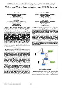
2. BACKGROUND 2.1 Long Term Evolution LTE was developed with the objective of providing high data rate with low latency and packet optimized packet radio access technology allowing flexible bandwidth deployments. Furthermore, LTE is accompanied by an evolution of the nonradio aspects of the complete system, under the term System Architecture Evolution (SAE) which includes the Evolved Packet Core (EPC) network. Together, LTE and SAE comprise the Evolved Packet System (EPS), where both the core network and the radio access are fully packet-switched. The architecture of the LTE system is shown in Figure 1. At a high level, the network is comprised of the Core Network (CN) and the Access Network (E-UTRAN). The CN is responsible for the overall control of the UE and establishment of the bearers. The main logical nodes of the EPC are: • PDN Gateway • Serving Gateway • Mobility Management Entity (MME). The UEs (User Equipment) are basically and mobile equipment used by users in the LTE network. The E-UTRAN is the collection of the eNodeBs or the LTE systems base stations. The Core network consists of several interacting entities. The Mobility Management Entity (MME) is the
31
International Journal of Computer Applications (0975 – 8887) Volume 133 – No.3, January 2016
Figure 1. LTE Architecture control node of the network which is responsible for several important activities like paging, handover and so on. All IP packets are served through the Serving Gateway which also serves as a local mobility anchor when UEs move between eNodeBs. The Packet Data Network Gateway (PDN-Gateway) connects the LTE network to the outer network. It is also responsible for QoS enforcement and flow-based charging according to rules from Policy Control and Charging Rules Function (PCRF). The Home Subscriber Server (HSS) is the database that contains all the subscribers information. There are interfaces which connects the nodes in the network. The LTE-Uu interface is used for data transfer between eNodeBs and UEs .The S1-MME interface connecting MME and eNodeB supports control between them. The S6a interface enables transfer of subscription and authentication data for authenticating/authorizing user access to the EPS between MME and HSS. The S11 interface between MME and Serving Gateway has functionalities for paging coordination and mobility. The S1-U interface between eNodeB and Serving Gateway is for the inter eNodeB path switching during handover. The interface between the serving and PDN gateways is S5/S8. It has slightly different implementations, namely S5 when network neutral and S8 if they are in different networks. The Gx interface is used for provisioning and removal of Policy and Charging Control (PCC) rules from the PCRF to the PDN Gateway and the transmission of traffic plane events from the PDN Gateway to the PCRF. The Rx interface between PCRF and the external network is used to exchange application level session information The SGi interface connects PDN Gateway to external network thereby enabling exchange of signals.
2.2 Software Defined Networking Software Defined Networking (SDN) is an emerging architecture that is dynamic, manageable, cost-effective, and adaptable, making it ideal for the high-bandwidth, dynamic nature of today’s applications. This architecture decouples the control plane and the data plane, enabling the control plane to become directly programmable and the underlying infrastructure to be abstracted for applications and network services. In Figure 2 the network intelligence is (logically) centralized in software based SDN controllers, which maintain a global view of the network. SDN simplifies the network devices since they need not process thousands of protocol standards but merely accept instructions from the SDN controllers .The most important aspect of having SDN implemented in the current network is that the network operators and
administrators can now configure these network devices programmatically. In addition to abstracting the network, SDN architectures support a set of APIs that make it possible to implement common network services, including routing, multicast, security, access control, bandwidth management, traffic engineering, quality of service, processor and storage optimization, energy usage and all forms of policy management, custom tailored to meet business objectives.
Figure 2. Logical View of SDN Architecture
3. PROPOSED SYSTEM In the proposed LTE system, network intelligence is shifted to the controller at the level of a tracking area. The tracking area is a logical area where the user can move around without updating the MME. The architecture of proposed system is shown in Figure 3. By incorporating the high level controller the control plane can be made programmable and it gives the flexibility to configure, manage, secure, and optimize network resources.
3.1 Advantages The possible optimizations that can be achieved in the modified 4G/LTE network are:
Turning off RF Transceivers: When an eNodeB is not currently serving any UEs, the radio transmitter can be powered down temporarily. In the current system, the radio transmitters are made to run round the clock irrespective of whether they serve any
32
International Journal of Computer Applications (0975 – 8887) Volume 133 – No.3, January 2016 UEs or not. There is no intelligence to control the functionality of an eNodeB in this aspect.
Low-power mode: Another possible optimization that could be introduced into an LTE network is to push the eNodeB into a low-power mode when it is inactive where it responds to the signals of the controller and acts as a simple switch, rest of the time.
Reduced power consumption: The functioning of a RF transceiver consumes a lot of power. Thus by turning off the component, one can reduce power consumption drastically.
Cost efficiency: By saving on power consumption, it is implied that a system with SDN implemented in 4G/LTE network is much more cost effective than the traditional system.
Easy evolution: Existing network equipment need not be replaced completely. New SDN capable devices can be added to the network along with the legacy systems without affecting operations.
4. USE CASES In this section a few scenarios depicting how the performance of the current LTE networks can be improved by implementing the SDN controller at the level of tracking area are discussed. The use cases mentioned below are implemented with the LTE-Sim simulator [1]. The simulator is now provided with the additional feature of showing the network topology by animation using OpenGL.
4.1 Go Green - Power Management
Figure 3. Proposed Architecture with SDN Enabled It also poses a wide range of advantages which are listed below:
Centralized management of the network: By shifting the intelligence away from the network components, SDN provides a centralized view to the whole network where the hardware is controlled by a centralized entity, thus reducing coupling to a significant extent. Abstraction of control-plane mechanism: By adopting SDN, the control-plane activities are abstracted to a significant extent the programmer no longer needs to bother about the way in which an instruction is conveyed to the network elements. It also allows for easier evolution of the entire network. Going Green: By adopting various measures to turn off RF emissions and also run the eNodeBs in low power mode whenever possible, lot of electricity is saved and also unnecessary radio emissions are curbed. Balanced load: The controller continuously monitors the load condition on each cell. In case it encounters heavy load on any cell, it decides for a re-distribution of the UEs to neighboring cell that provides the best receiving power for the UE.
A UE can fall under the coverage limits of more than one eNodeB. It is by default, attached to the eNodeB which offers better signal strength and quality. In the conventional model, all eNodeBs are kept active round the clock, irrespective of whether UEs are attached to it or not. This leads to a lot of wastage in power and also results in high levels of radio frequency emissions. When monitored by a SDN controller, eNodeBs which are relatively idle can be forced to handover the attached UEs to nearby eNodeBs. Following that, the radio transmitter of that eNodeB can be powered down, making the eNodeB reactive to the command of the SDN controller alone (say a low-power state). When the traffic in that region rises sometime later, the eNodeB can be powered up pretty soon and put back into action. The scenario is divided into 2 cases based on when to turn off the transceiver of the eNodeB. • Without Smart Handover - An eNodeB will become passive when UE count in its cell is zero. • With Smart Handover - An eNodeB will become passive when number of UEs in its cell reaches below the threshold. The threshold value is calculated by the formula Threshold = |Average number of UEs| / 10 In both the cases the eNodeB will become active when the number of UEs is more than threshold value and/or a UE cannot be served satisfactorily by surrounding eNodeB.
4.2 Load Balancing Load imbalance is one of the major problems in communication networks. The goal of load balancing is to reduce the cell congestion and provide a self - organizing network with no compromise on QoS. The SDN controller has a track of the number of UEs within the coverage of each cell, and in case of a load greater than seventy percentage (of the upper limit), the UEs are handed over accordingly to the neighboring cells which have both a balanced load and provides a good signal strength. The advantage of load balancing in LTE network is that the cell load is balanced
33
International Journal of Computer Applications (0975 – 8887) Volume 133 – No.3, January 2016 which will increase the system capacity by reducing congestion in heavily loaded cells.
6.1 Evaluation for Go Green scenario Table 1. Performance Comparison Go Green
4.3 Disaster Management Natural disasters like an earthquake, Tsunami or a heavy storm could knock down the transmission towers. When this happens, the UE devices that are attached to those eNodeBs are paralyzed. They are unable to communicate to their dedicated eNodeB and also it is the same eNodeB which stores the details pertaining to the connected UE, hence leading to loss of valuable information in case of damage to eNodeB. In order to respond to the situation and restore communication, a need for the SDN controller is realized. It manages high traffic levels with fewer eNodeBs to serve the customers by identifying the functional eNodeBs on the fly. The SDN Controller manages traffic efficiently among them, balancing the load without causing the system to collapse.
No. of UES
Average Sleep Time in STOCK LTE SIM (sec)
Average Sleep Time (Without Smart Handover) (sec)
Average Sleep Time (With Smart Handover) (sec)
15
0
11.957
18.0977
20
0
4.3965
6.2714
25
0
3.7953
4.9524
27
0
3.5238
5.7
5. EVALUATION METRICS
30
0
1.7084
5.1428
The use cases mentioned above can be evaluated using the metrics given below.
32
0
0.4752
3.9
35
0
1.9363
2.0905
40
0
0.3809
3.3762
45
0
0
1.5143
Reduction on Power Consumption: During periods of low traffic, when there are too few UEs served by an eNodeB, they can be handed over to the neighboring cells and the radio transmitter of the eNodeB can be turned off transiently, making it enter a low- power mode. This saves power and unnecessary radio permissions are curbed. The changes can be reverted when the traffic increases. Load Balancing: The present day LTE systems do not provide very efficient load balancing schemes. The modified system involves dynamic adaption of the threshold for number of UE connections per eNodeB. The peak hours will have higher UE connections per eNodeB when compared with other times. By adjusting the threshold and forcing a few handovers to maintain a more uniform distribution of load across the eNodeBs, one can achieve optimal load balancing in the Network. The threshold value can be decided by the application or learnt from the traffic patterns in recent history. This load balancing feature also finds use in case of a natural disaster where the towers are physically damaged.
6. PERFORMANCE COMPARISON
Figure 4 shows the graph where the average time duration for which the eNodeBs are offline are plotted using the values given in Table 1. It can be seen that the stock LTE-Sim does not have any power saving mechanism and as a result no eNodeB is switched off. It is also observed that in the system without Smart Handover the period of time during which the eNodeBs are switched off is considerably lower than the system with Smart Handover. Hence it is clear that there is considerable power savings when Go Green with Smart Handover is employed.
6.2 Evaluation for Load Balancing scenario Figure 5 shows the performance comparison graph between the total number of UEs in the scenario and the standard deviation of the eNodeB loads which is plotted using the values given in Table 2. The standard deviation is calculated by using the formula Standard Deviation = current load of enodeB – mean Load Number of cells0.5
The performance of the stock LTE-Sim system and the system with SDN Controller enabled is compared using the metrics described above.
34
International Journal of Computer Applications (0975 – 8887) Volume 133 – No.3, January 2016
Figure 4. Performance Graph for Go Green scenario.
Figure 5. Performance Graph for Load Balancing Scenario Table 2. Performance Evaluation – Load Balancing No. of UES
Standard Deviation of Load (Without load balancing)
Standard Deviation of Load (with Load balancing)
25
18.3168
17.5863
30
21.5582
19.5851
35
21.3587
15.2659
40
22.399
21.5125
45
21.0337
16.6703
50
24.9287
17.1844
It is observed that with the Load Balancing scheme enabled, the deviation in the number of UEs per eNodeB is minimal whereas without Load Balancing there is a sharp deviation in the number of UEs per eNodeB. Hence it is clear that the Load Balancing mechanism provides a better system performance by reducing the imbalance in load among the eNodeBs.
7. RELATED WORK The following papers were a huge inspiration for the work
central controller and radio elements, hence is capable of providing better performance in dense deployments. SoftRAN is found useful in realizing the advantages of having a logically centralized control plane.
SoftRAN [2] was introduced in a perspective to visualize a virtual big-base station comprised of the
CellSDN [3] is one of the recent ventures in adopting SDN into wireless environment by creating Software Defined Cellular Networks. It helps to overcome the disadvantages of currently inflexible nature of wireless networks, complex control-plane protocols and vendor specific configuration interfaces. It simplifies the design and management of cellular data networks.
8. CONCLUSION In this paper the SDN controller has been implemented for the use cases mentioned and the control plane activities have been successfully identified and decoupled. The intelligence or decision making is abstracted to the controller which now becomes responsible for all decision making activities. Usage of the SDN controller has successfully improved the power saving capabilities as well as load handling capabilities of the LTE network. Thus LTE networks stand to gain a lot when SDN concepts are introduced. A possible improvement for the load balancing scheme would be to implement a History based Load Balancing scheme wherein the past load of an eNodeB is taken in to account before any decision on balancing the load is made.
35
International Journal of Computer Applications (0975 – 8887) Volume 133 – No.3, January 2016
9. REFERENCES [1] LTESimsourcecode,http://telematics.poliba.it/index.php/ en/?option=comcontent & view=article & id=158Itemid=lang=en [2] Aditya Gudipati, Daniel Perry, Li Erran Li, Sachin Katti. (2013) SoftRAN: Software Defined Radio Access Network, Proceedings of the second ACM SIGCOMM workshop on Hot topics in Software Defined Networking, pp.25- 30 [3] Li Erran Li, Z. M. Mao, Jennifer Rexford. (2012) Towards software defined cellular networks, 2012 European Workshop on Software Defined Networking, IEEE, pp.7-12. [4] Giuseppe Piro, Luigi Alfredo Grieco, Gennaro Boggia, Francesco Capozzi, Pietro Camarda. (2011) Simulating LTE Cellular Systems: An Open Source Framework. Vol. 60 No. 2.
IJCATM : www.ijcaonline.org
[5] Nick Feamster, Associate Professor, Georgia Institute of Technology. Software Defined Networking video course. https://www.coursera.org/course/sdn. [6] Open Network Foundation (ONF) White Paper. (2012) Software Defined Networking: The new normfornetworks,pp112.https://www.opennetworking.or g/images/stories/downloads/ sdn- resources/whitepapers/wp-sdn-newnorm.pdf [7] LTE: General Packet Radio Service (GPRS) enhancements for Evolved Universal Terrestrial Radio Access Network (E-Utran) access (3GPP TS23.401 version 8.18.0 Release 8) [8] http://www.cse.unt.edu/ rdantu/FALL 2013 WIRELESS NETWORKS/LTE Alcatel White Paper.pdf [9] LTE - The UMTS Long Term Evolution: From TheorytoPractice,http://196.29.172.66:8080/jspui/bitstrea m/123456789/4300/1/E603.pdf
36


![HP SDN Controller Architecture [PDF]](https://m.moam.info/img/260x300/hp-sdn-controller-architecture-pdf_64b1bd2a098a9e794f8b4594.jpg)