There have been many difficult times and obstacles during my Ph.D. years. Every
time I was .... 4.2 Threats in Network Coding Systems for Wireless Networks . . . . .
64 ..... For example, in many proposed systems with dynamic topology-aware.
SECURE AND ROBUST COMMUNICATION IN WIRELESS MESH NETWORKS
A Dissertation Submitted to the Faculty of Purdue University by Jing Dong
In Partial Fulfillment of the Requirements for the Degree of Doctor of Philosophy
December 2009 Purdue University West Lafayette, Indiana
ii
In dedication to my parents for their support, patience, and unconditional love 谨献给我亲爱的父亲和母亲
iii
ACKNOWLEDGMENTS It would not be possible for you to be reading this dissertation if it were not for the help of many people in my life. While each and every one of them has made an impact on my life, I would like to give special thanks to some of whom have been particularly instrumental to the completion of this work. My utmost gratitude goes to my major advisor, Prof. Cristina Nita-Rotaru. Cristina not only provided me with in-depth guidance on my research and exterted active effort on my career development, she also cared about me deeply on a more personal level. There have been many difficult times and obstacles during my Ph.D. years. Every time I was on such an occastion, her thoughtful encouragement and advice have always helped me in moving forward. I am sure her mark on my growth in this period, both professionally and personally, will benefit me for many ages to come. A special thanks also goes to Prof. Reza Curtmola. Reza was a post-doc with my advisor for one year, during which we collaborated closely. He shaped the contents and form of the dissertation in important ways. Many thanks also go to Prof. Mike Atallah, Prof. Sonia Fahmy, and Prof. David Yau for serving on my advisory committee and for taking their precious time to write reference letters for me. Their insightful feedbacks on my preliminary proposal have helped me a great deal in the completion of the dissertation. I also would like to give special thanks to Prof. David Yau for advicing part of the research work presented in this dissertation. My academic development in Purdue was shaped by many professors in the department, including Prof. Dongyan Xu, Prof. Gopal Pandurangan, Prof. David Yau, Prof. Ninghui Li, Prof. Sunil Prabhakar, Prof. Elisa Bertino, and Prof. Suresh Jagannathan. While it is difficult to thank each one of them, I would like to give special
iv thanks to Prof. Dongyan Xu for being my initial acdemic advisor and for guiding me through the beginning of my Ph.D. career. I also would like to give special thanks to Prof. Gopal Pandurangan for sharing his expertise in advanced algorithms and randomized algorithms. Many of the techniques that I learned in his classes have been very helpful for me in solving the research problems I encountered. My life in Purdue would not be as much fun if it were not for the presence of my friends, labmates, officemates, and classmates. Many thanks to the present and former members of the DS2 group, David Zage, Jeff Seibert, Camil Kaspar, Erik Ackmann, Andy Newell, and Mercan Topkara. Many thanks to my friends, officemates, and classmates, Hong Chen, Tianchen Li, Ziqing Mao, Qun Ni, Jinguang Li, Wenchang Liu, Yan Wu, Ian Molloy, Jingfeng Yan, Yang Wang, Qihua Wang, Qiqi Wang, Ashish Kundu, Roman Chertov, Ashish Kamra. On a more personal note, I would like to thank my family. My parents have been supportative of my education all along the way, even though they have to work extrahours to support the family. My wife Le Chen cherished me through difficult times and comforted me when I have doubt on my abilities. Without her encouragement and companionship, I probably would have taken much longer to finish this dissertation.
v
TABLE OF CONTENTS Page LIST OF TABLES . . . . . . . . . . . . . . . . . . . . . . . . . . . . . . . .
ix
LIST OF FIGURES . . . . . . . . . . . . . . . . . . . . . . . . . . . . . . .
x
ABSTRACT . . . . . . . . . . . . . . . . . . . . . . . . . . . . . . . . . . .
xiii
1 INTRODUCTION . . . 1.1 Motivation . . . . . 1.2 Dissertation Focus 1.3 Organization . . .
. . . .
. . . .
. . . .
. . . .
. . . .
. . . .
. . . .
. . . .
. . . .
. . . .
. . . .
. . . .
. . . .
. . . .
. . . .
. . . .
. . . .
. . . .
. . . .
. . . .
. . . .
. . . .
. . . .
1 2 3 6
2 SYSTEM AND ADVERSARIAL MODEL . . . . . . . . . . . . . . . . . 2.1 System Model . . . . . . . . . . . . . . . . . . . . . . . . . . . . . . 2.2 Adversarial Model . . . . . . . . . . . . . . . . . . . . . . . . . . .
8 8 8
3 ROBUST TOPOLOGY-AWARE ADAPTATION . . . . . . . . 3.1 High-Throughput Mesh-Based Multicast Routing . . . . . 3.1.1 High-Throughput Metrics . . . . . . . . . . . . . . 3.1.2 High-Throughput Mesh-Based Multicast Routing . 3.2 Attacks against High-Throughput Multicast . . . . . . . . 3.2.1 Adversarial Model and Goal . . . . . . . . . . . . . 3.2.2 Attacks . . . . . . . . . . . . . . . . . . . . . . . . 3.2.3 Metric Manipulation Attacks . . . . . . . . . . . . 3.2.4 Impact of Metric Manipulation Attacks on Routing 3.3 Secure High-Throughput Multicast Routing . . . . . . . . 3.3.1 Authentication Framework . . . . . . . . . . . . . . 3.3.2 S-ODMRP Overview . . . . . . . . . . . . . . . . . 3.3.3 RateGuard Overview . . . . . . . . . . . . . . . . . 3.3.4 S-ODMRP Detailed Description . . . . . . . . . . . 3.3.5 Impact of False Positives . . . . . . . . . . . . . . . 3.3.6 Practical Implementation Issues . . . . . . . . . . . 3.4 S-ODMRP Security Analysis . . . . . . . . . . . . . . . . . 3.4.1 Attack Impact . . . . . . . . . . . . . . . . . . . . . 3.4.2 RateGuard Attack Resiliency . . . . . . . . . . . . . 3.4.3 Limitations of S-ODMRP . . . . . . . . . . . . . . . 3.5 Experimental Evaluation . . . . . . . . . . . . . . . . . . . 3.5.1 Experimental Methodology . . . . . . . . . . . . . . 3.5.2 Effectiveness of Metric Manipulation Attacks . . . .
. . . .
. . . . . . . . . . . . . . . . . . . . . . .
. . . .
. . . . . . . . . . . . . . . . . . . . . . .
. . . .
. . . . . . . . . . . . . . . . . . . . . . .
. . . .
. . . . . . . . . . . . . . . . . . . . . . .
. . . . . . . . . . . . . . . . . . . . . . .
10 12 13 15 18 18 19 21 22 23 24 24 25 27 34 34 36 36 41 42 42 43 45
vi
3.6 3.7
3.5.3 Effectiveness of the Defense . 3.5.4 Defense Resiliency to Attacks 3.5.5 Overhead of S-ODMRP . . . . Related Work . . . . . . . . . . . . . Conclusion . . . . . . . . . . . . . . .
. . . . .
. . . . .
. . . . .
. . . . .
. . . . .
. . . . .
. . . . .
. . . . .
. . . . .
. . . . .
. . . . .
. . . . .
. . . . .
. . . . .
. . . . .
. . . . .
. . . . .
Page 47 49 49 51 53
4 SECURITY THREATS IN WIRELESS NETWORK CODING SYSTEMS 4.1 Network Coding-based Wireless Systems . . . . . . . . . . . . . . . 4.1.1 Network Model . . . . . . . . . . . . . . . . . . . . . . . . . 4.1.2 Intra-flow Network Coding . . . . . . . . . . . . . . . . . . . 4.1.3 Inter-flow Network Coding . . . . . . . . . . . . . . . . . . . 4.2 Threats in Network Coding Systems for Wireless Networks . . . . . 4.2.1 Adversarial Model . . . . . . . . . . . . . . . . . . . . . . . 4.2.2 Intra-flow Network Coding . . . . . . . . . . . . . . . . . . . 4.2.3 Inter-flow Network Coding . . . . . . . . . . . . . . . . . . . 4.3 Experimental Evaluation . . . . . . . . . . . . . . . . . . . . . . . . 4.3.1 Methodology. . . . . . . . . . . . . . . . . . . . . . . . . . . 4.3.2 Results for Intra-flow Network Coding . . . . . . . . . . . . 4.3.3 Results for Inter-flow Network Coding . . . . . . . . . . . . 4.4 Conclusion . . . . . . . . . . . . . . . . . . . . . . . . . . . . . . . .
54 55 55 55 60 64 64 65 67 72 72 74 76 77
5 POLLUTION ATTACKS AND DEFENSES IN WIRELESS INTRA-FLOW NETWORK CODING SYSTEMS . . . . . . . . . . . . . . . . . . . . . . 5.1 Related Work . . . . . . . . . . . . . . . . . . . . . . . . . . . . . . 5.2 System and Adversarial Model . . . . . . . . . . . . . . . . . . . . . 5.2.1 System Model . . . . . . . . . . . . . . . . . . . . . . . . . . 5.2.2 Security and Adversarial Model . . . . . . . . . . . . . . . . 5.3 Limitations of Previous Work . . . . . . . . . . . . . . . . . . . . . 5.4 The DART scheme . . . . . . . . . . . . . . . . . . . . . . . . . . . 5.4.1 Scheme Description . . . . . . . . . . . . . . . . . . . . . . . 5.4.2 Checksum Computation and Verification . . . . . . . . . . . 5.4.3 Pipelining Across Generations . . . . . . . . . . . . . . . . . 5.4.4 Security Analysis . . . . . . . . . . . . . . . . . . . . . . . . 5.5 The EDART Scheme . . . . . . . . . . . . . . . . . . . . . . . . . . 5.5.1 Scheme Description . . . . . . . . . . . . . . . . . . . . . . . 5.5.2 Security Analysis . . . . . . . . . . . . . . . . . . . . . . . . 5.5.3 Selection of δ and α . . . . . . . . . . . . . . . . . . . . . . . 5.6 Attacker Identification . . . . . . . . . . . . . . . . . . . . . . . . . 5.6.1 Assumptions . . . . . . . . . . . . . . . . . . . . . . . . . . . 5.6.2 DART-AI: DART with Attacker Identification . . . . . . . . 5.6.3 EDART-AI: EDART with Attacker Identification . . . . . . 5.7 Experimental Evaluation . . . . . . . . . . . . . . . . . . . . . . . . 5.7.1 MORE in a Nutshell . . . . . . . . . . . . . . . . . . . . . .
78 80 83 83 84 85 87 88 91 93 95 100 101 103 106 106 107 107 109 114 115
vii
5.8
5.7.2 Experimental Methodology . . . . . . . . 5.7.3 Impact of Pollution Attacks . . . . . . . 5.7.4 Limitations of Previous Solutions . . . . 5.7.5 Evaluation of DART and EDART . . . . 5.7.6 Evaluation of DART-AI and EDART-AI Conclusion . . . . . . . . . . . . . . . . . . . . .
. . . . . .
. . . . . .
. . . . . .
. . . . . .
. . . . . .
. . . . . .
. . . . . .
. . . . . .
. . . . . .
. . . . . .
. . . . . .
Page 116 119 120 121 125 129
6 POLLUTION ATTACKS AND DEFENSES IN WIRELESS INTER-FLOW NETWORK CODING SYSTEMS . . . . . . . . . . . . . . . . . . . . . . 6.1 Related Work . . . . . . . . . . . . . . . . . . . . . . . . . . . . . . 6.2 System Model and Adversarial Model . . . . . . . . . . . . . . . . . 6.2.1 System Model . . . . . . . . . . . . . . . . . . . . . . . . . . 6.2.2 Adversarial Model . . . . . . . . . . . . . . . . . . . . . . . 6.3 Pollution Attacks on Inter-Flow Network Coding Systems . . . . . . 6.3.1 Plain Packet Pollution . . . . . . . . . . . . . . . . . . . . . 6.3.2 Coded Packet Pollution . . . . . . . . . . . . . . . . . . . . 6.3.3 The Cross-flow Pollution Phenomenon . . . . . . . . . . . . 6.4 Pollution Defense: CodeGuard . . . . . . . . . . . . . . . . . . . . . 6.4.1 Assumptions . . . . . . . . . . . . . . . . . . . . . . . . . . . 6.4.2 CodeGuard Overview . . . . . . . . . . . . . . . . . . . . . . 6.4.3 Detection of Polluted Packets . . . . . . . . . . . . . . . . . 6.4.4 Attacker Node Identification . . . . . . . . . . . . . . . . . . 6.4.5 Security Analysis . . . . . . . . . . . . . . . . . . . . . . . . 6.4.6 Overhead Analysis . . . . . . . . . . . . . . . . . . . . . . . 6.5 Experimental Evaluation . . . . . . . . . . . . . . . . . . . . . . . . 6.5.1 Experimental Methodology . . . . . . . . . . . . . . . . . . . 6.5.2 Results from Illustrative Scenarios . . . . . . . . . . . . . . . 6.5.3 Results from Random Network Scenarios . . . . . . . . . . . 6.6 Conclusion . . . . . . . . . . . . . . . . . . . . . . . . . . . . . . . .
130 133 133 133 134 135 135 137 137 138 138 139 140 142 145 148 149 149 151 152 155
7 EFFICIENT APPLICATION LAYER SECURITY: SECURE GROUP COMMUNICATION . . . . . . . . . . . . . . . . . . . . . . . . . . . . . . . . 7.1 Related Work . . . . . . . . . . . . . . . . . . . . . . . . . . . . . . 7.2 System Model and Design Goals . . . . . . . . . . . . . . . . . . . . 7.3 SeGrOM Framework and Protocols . . . . . . . . . . . . . . . . . . 7.3.1 Overview . . . . . . . . . . . . . . . . . . . . . . . . . . . . 7.3.2 Secure Local Data Delivery . . . . . . . . . . . . . . . . . . 7.3.3 Secure Group Overlay . . . . . . . . . . . . . . . . . . . . . 7.3.4 Global Data Delivery on the Secure Overlay . . . . . . . . . 7.3.5 Client Member Revocation . . . . . . . . . . . . . . . . . . . 7.4 Performance Analysis . . . . . . . . . . . . . . . . . . . . . . . . . . 7.4.1 Communication Path Length for SeGrOM Join . . . . . . . 7.4.2 Communication Path Length for Centralized Join . . . . . .
156 158 161 163 163 165 166 167 170 174 174 177
viii Page 7.4.3 7.5
7.6
Bandwidth Cost and Latency Ratio for ized Schemes and SeGrOM . . . . . . . Experimental Evaluation . . . . . . . . . . . . 7.5.1 Experimental Methodology . . . . . . . 7.5.2 Protocol Performance and Robustness 7.5.3 Protocol Overhead . . . . . . . . . . . Conclusion . . . . . . . . . . . . . . . . . . . .
Join Between Central. . . . . . . . . . . . . . . . . . . . . . . . . . . . . . . . . . . . . . . . . . . . . . . . . . . . . . . . . . . . . . . . . . . . . . . .
178 179 180 181 182 187
8 CONCLUSION AND FUTURE WORK . . . . . . . . . . . . . . . . . .
189
LIST OF REFERENCES . . . . . . . . . . . . . . . . . . . . . . . . . . . .
193
VITA . . . . . . . . . . . . . . . . . . . . . . . . . . . . . . . . . . . . . . .
205
ix
LIST OF TABLES Table
Page
5.1
Computational cost for checksum generation and verification. . . . . .
121
7.1
Notations used in Algorithms 7, 8, 9 and 10. . . . . . . . . . . . . . . .
164
x
LIST OF FIGURES Figure
Page
1.1
An example wireless mesh network. . . . . . . . . . . . . . . . . . . . .
1
3.1
An example of ODMRP-HT mesh creation . . . . . . . . . . . . . . . .
17
3.2
Metric manipulation attack 1 . . . . . . . . . . . . . . . . . . . . . . .
22
3.3
Metric manipulation attack 2 . . . . . . . . . . . . . . . . . . . . . . .
23
3.4
Basic procedures used in the S-ODMRP protocol description . . . . . .
27
3.5
The effectiveness of metric attacks on ODMRP-HT . . . . . . . . . . .
46
3.6
The effectiveness of S-ODMRP for different attacks . . . . . . . . . . .
48
3.7
Impact of the False-Accusation attack on S-ODMRP . . . . . . . . . . .
49
3.8
The overhead of S-ODMRP . . . . . . . . . . . . . . . . . . . . . . . .
50
4.1
Illustrative examples for intra-flow network coding. . . . . . . . . . . .
56
4.2
An illustration of plain packets, generation, and coded packets in intraflow network coding systems. . . . . . . . . . . . . . . . . . . . . . . .
56
4.3
Illustrative examples for inter-flow network coding. . . . . . . . . . . .
61
4.4
An example scenario illustrating partial and full decoding in an inter-flow network coding system. . . . . . . . . . . . . . . . . . . . . . . . . . . .
62
4.5
Average throughput under multiple packet dropping attackers. . . . . .
74
4.6
Throughput CDF under single packet dropping attacker. . . . . . . . .
75
4.7
Total network throughput under different number of attackers for an interflow coding system. . . . . . . . . . . . . . . . . . . . . . . . . . . . . .
76
5.1
An example network for illustrating the process in DART. . . . . . . .
90
5.2
An illustration of the multi-attacker case. . . . . . . . . . . . . . . . . .
105
5.3
False positive probability of DART-AI. . . . . . . . . . . . . . . . . . .
109
5.4
Roofnet topology and link qualities. . . . . . . . . . . . . . . . . . . . .
116
5.5
The throughput CDF in the presence of a single attacker. . . . . . . . .
119
5.6
Impracticality of previous work. . . . . . . . . . . . . . . . . . . . . . .
120
xi Figure
Page
5.7
The throughput of DART and EDART under benign case. . . . . . . .
122
5.8
Latency CDF of DART and EDART under benign case. . . . . . . . .
122
5.9
The throughput and latency CDF of DART and EDART. . . . . . . .
123
5.10 Bandwidth and computational overhead of DART and EDART. . . . .
124
5.11 Throughput under benign network for defense with attacker identification scheme. . . . . . . . . . . . . . . . . . . . . . . . . . . . . . . . . . . .
126
5.12 Throughput under 5 random attackers with and without attacker identification. . . . . . . . . . . . . . . . . . . . . . . . . . . . . . . . . . . .
126
5.13 Attacker identification latency. . . . . . . . . . . . . . . . . . . . . . . .
127
5.14 The proactive overhead of attacker identification. . . . . . . . . . . . .
127
5.15 Reactive bandwidth overhead for attacker identification for 5 attackers.
128
6.1
Pollution attacks on inter-flow coding systems. . . . . . . . . . . . . . .
136
6.2
An example coding tree. . . . . . . . . . . . . . . . . . . . . . . . . . .
146
6.3
Throughput for different offered loads. . . . . . . . . . . . . . . . . . .
151
6.4
Throughput with and without CodeGuard defense in a random network.
152
6.5
Attack impact on aggregate throughput of flows with 20 attackers. . . .
152
6.6
Average delay of attacker identification. . . . . . . . . . . . . . . . . .
153
6.7
Proactive bandwidth (left-Y) and computation (right-Y) overheads. . .
154
6.8
Reactive bandwidth (left-Y) and computation (right-Y) overheads. . .
154
7.1
Example mesh network. . . . . . . . . . . . . . . . . . . . . . . . . . .
162
7.2
Conceptual abstraction of the secure group overlay. . . . . . . . . . . .
166
7.3
Node distance relationships. . . . . . . . . . . . . . . . . . . . . . . . .
175
7.4
The latency and bandwidth cost ratio in a join operation between a centralized scheme and SeGrOM. . . . . . . . . . . . . . . . . . . . . . . .
179
7.5
Delivery ratio of SeGrOM protocols. . . . . . . . . . . . . . . . . . . .
182
7.6
Computation overhead of SeGrOM protocols. . . . . . . . . . . . . . .
183
7.7
Join/leave bandwidth overhead an latency of SeGrOM protocols.
. . .
184
7.8
Peak bandwidth of SeGrOM protocols. . . . . . . . . . . . . . . . . . .
185
7.9
Total bandwidth overhead vs. data rates. . . . . . . . . . . . . . . . . .
186
xii Figure
Page
7.10 Total bandwidth overhead vs. group dynamics. . . . . . . . . . . . . .
186
7.11 The frequency of CA contact required for a join in a network with 100 routers. . . . . . . . . . . . . . . . . . . . . . . . . . . . . . . . . . . .
187
xiii
ABSTRACT Dong, Jing. Ph.D., Purdue University, December 2009. Secure and Robust Communication in Wireless Mesh Networks. Major Professor: Cristina Nita-Rotaru. Wireless mesh networks (WMNs) have become the focus of research in recent years, owing to their great promise in realizing numerous next-generation wireless services. Driven by the demand for rich and high-speed content access, recent research has focused on developing high performance communication protocols, while the security of the proposed protocols has received relatively little attention. However, given the wireless and multi-hop nature of the communication, WMNs are subject to a wide range of security threats. In this dissertation, we study the security of two main design methodologies that emerged from recent research for achieving high performance data delivery in WMNs, namely, dynamic topology-aware adaptation and network coding. In addition, we also study the principles of designing efficient application layer security protocols for WMNs. Dynamic topology-aware adaption presents an important design principle that underlies many high performance network layer protocols proposed for WMNs. We study the unique security threats that exploit the cooperative nature of such protocols. The identified attacks can allow even only a few attacker nodes to distort the path selection process in the entire network and to gain control on a large portion of the traffic in the network. Our proposed defense mechanism relies on passive measurements for detecting attacks and cooperative accusation for identifying and isolating attacker nodes. Through both analysis and experimental evaluations, we show that our defense protocol is effective and incurs low overhead. Network coding is a major performance improvement technique for WMNs that has emerged in recent years. Numerous practical systems have demonstrated that
xiv network coding is able to achieve significantly improved performance over the traditional packet forwarding approach. We focus on studying the security aspects of applying network coding on WMNs. We first perform a systematic security analysis on existing network coding systems and uncover numerous security threats on various system components. We then focus on addressing a severe and generic attack against network coding systems, known as packet pollution attack. We propose the first practical defense mechanisms to pollution attacks for both of the two major wireless network coding approaches, intra-flow network coding and inter-flow network coding. Our defense uses efficiently computable random linear checksums and an efficient traceback mechanism to filter out polluted packets and identify attacker nodes. The experimental results show that the proposed mechanisms can effectively filter out polluted packets and quickly identify and isolate attacker nodes while incurring small computation and bandwidth overhead. On the application layer, we demonstrate the unique challenges and opportunities in designing efficient security protocols. We focus on the problem of providing data confidentiality for group communication on WMNs, and present a protocol framework designed specifically for WMNs. Our design employs decentralized group membership, promotes localized communication, and exploits the nature of wireless broadcast. Through both analytical and experimental evaluations, we demonstrate the importance of the design principles for the efficiency and performance of the application layer protocols on WMNs.
1
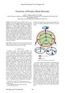
1 INTRODUCTION In recent years, wireless mesh networks (WMNs) have emerged as a key enabling technology for the next-generation wireless networking. A WMN typically consists of a set of stationary wireless mesh routers and a set of mesh clients, as shown in Figure 1.1. Mesh routers form a self-organized multi-hop wireless network, with nodes dynamically maintaining the mesh connectivity among themselves via ad hoc networking protocols, such as DSR [1], AODV [2] for unicast and ODMRP [3], MAODV [4] for multicast. Mesh clients connect to mesh routers and communicate with each other via the multi-hop backbone network formed by the mesh routers. The self-maintenance feature of WMNs and the low cost of wireless routers make WMNs a promising technology for providing economic solutions for a wide range of applications, such as broadband community wireless service, enterprise wireless networking, security surveillance, and emergency networking [5]. In addition, through bridging and gateway functions of mesh routers, WMNs can be easily integrated with other networks, such as Internet, cellular networks, wireless local area networks (WLAN), wireless personal area networks (WPAN), wireless metropolitan area net-
Mesh Router Mesh Client
Figure 1.1. An example wireless mesh network.
2 works (WMAN), and sensor networks. As an example application, WMNs can be easily deployed for providing broadband wireless access for a community or enterprise environment by having a few mesh routers serve as Internet gateways and other mesh routers serve as relays [5]. Compared to the alternative approach of using cellular networks, WMNs are much more economical and can support a much higher bandwidth. Compared to the approach of using 802.11 WLANs, WMNs avoid the inconvenience and cost of wiring, and thus are much more flexible and can be deployed incrementally as needed. As another example, in the case of disaster or other emergency scenario, infrastructure based communications, such as cellular networks, may be destroyed or unavailable. By simply placing mesh routers at desired locations, a WMN can be easily established, enabling communication among emergency response teams [5]. Given the large number of potential applications, WMNs have attracted tremendous interest from both academia and industry, and resulted in dedicated subworking groups in several industry standards groups, such as 802.11, 802.15, and 802.16 [6–8].
1.1 Motivation Driven by the increasing demand for rich and high-speed content access, recent research in WMNs has focused on developing high performance communication protocols, and given rise to two general design approaches, dynamic topology-aware adaptation and dynamic network coding. The main principle of dynamic topology-aware adaptation is to improve performance by dynamically adjusting protocol structure to accommodate the unstable nature of wireless links. Dynamic network coding, on the other hand, improves performance by exploiting the broadcast nature of wireless communication to effectively make use of the common occurrence of packet overhearing in wireless networks. Both approaches have been adopted in a wide range of practical systems, and demonstrated significant improvement in system performance.
3 In contrast, in the quest for performance, security and robustness of system design have received relatively little attention. However, security is a primary concern in wireless mesh networks. Firstly, wireless communication is inherently open: Attackers can easily set up rogue nodes to mount a wide variety of attacks, such as eavesdropping, jamming, man-in-the-middle and spoofing. Secondly, software bugs, mis-configurations, and easy physical access all make mesh routers easier to be subverted by attackers and result in insider attacks. Finally, even in a benign environment, the variability and unpredictability of wireless signals and the susceptibility of mesh routers to failures also demand for robust communication protocols that can tolerate topology variations and even a certain level of mis-behavior. The lack of consideration on security and robustness makes many proposed systems extremely vulnerable to attacks and mis-behavior, thus unsuitable for real-world deployment. For example, in many proposed systems with dynamic topology-aware adaptation, even a single mis-behaving node can cause an epidemic effect in the network and result in a significant negative impact on the protocol performance. Unfortunately, achieving security in wireless networks is much more challenging than in wired networks, especially for protocols aiming at high performance. On the one hand, wireless networks have a much more open communication environment and are subjected to a much wider range of attacks; on the other hand, wireless networks are much more limited in resource, thus only lightweight solutions can be applied. As a consequence, many security protocols proposed for wired networks are inapplicable in the wireless environment.
1.2 Dissertation Focus This dissertation constitutes an effort to reconcile security and performance in system designs for wireless networks and to pave the way towards secure and high performance communications in WMNs. We focus on the security of two general approaches in achieving high performance communication, dynamic topology-aware
4 adaptation and dynamic network coding, which can serve as key building blocks in building a secure and high performance communication platform for WMNs. We also study the design of security protocols in the user application layer, revealing key differences in design principles as compared to wired networks. In summary, the key contributions of this dissertation are as follows. • Dynamic topology-aware adaptation is an important design methodology for achieving for high performance communication for WMNs and has been incorporated in many practical system designs. Using a high performance multicast protocol as a concrete and representative example, we analyze the security vulnerabilities of this approach, identify its security risks, and propose an effective and lightweight solution to consolidate such systems. In particular, we identify attacks that exploit the local estimation and global aggregation of the metric to allow attackers to attract a large amount of traffic. We show that these attacks are very effective against multicast protocols based on high-throughput metrics, and conclude that aggressive path selection is a double-edged sword: While it maximizes throughput, it also increases attack effectiveness in the absence of defense mechanisms. Our approach to defend against the identified attacks combines measurement-based detection and accusation-based reaction techniques. The solution accommodates transient network variations and is resilient against attempts to exploit the defense mechanism itself. A detailed security analysis of our defense scheme establishes bounds on the impact of attacks. We demonstrate both the attacks and our defense using ODMRP, a representative multicast protocol for wireless mesh networks, and SPP, an adaptation of the well-known ETX unicast metric to the multicast setting. • Network coding has emerged in recent years as a new communication paradigm that can significantly improve the efficiency of network protocols for WMNs. Several real-world systems have been proposed to leverage network coding in wireless networks. Although the theoretical foundations of network coding are
5 well understood, a real-world system needs to solve a plethora of practical aspects before network coding can meet its promised potential. These practical design choices expose network coding systems to a wide range of attacks. We identify two general frameworks (intra-flow and inter-flow network coding) that encompass all existing network coding-based systems proposed in wireless networks. Our systematic analysis of the components of these frameworks reveals vulnerabilities to a wide range of attacks, which may severely degrade system performance. We then focus on addressing a severe security threat against network coding systems, known as packet pollution attack. For intraflow network coding systems, we propose a lightweight defense scheme that uses time-based authentication in combination with random linear transformations to efficiently filter out polluted packets. We also propose efficient attacker identification schemes that enable quick attacker isolation and the selection of attacker-free paths, achieving additional performance improvement. For interflow network coding, we first perform a detailed analysis on the impact of pollution attacks and reveal that pollution attacks can result in complicated effects on the data delivery that depend not only on the network topology, but also on the location and strategy of the attacker nodes. We then propose a reactive attestation-based defense mechanism that uses efficient bit-level traceback and a novel cross-examination technique to unequivocally identify attacker nodes. We perform detailed security analysis and extensive simulation experiments for our defense mechanisms for both intra-flow and inter-flow coding systems. Our analysis and experimental results show that our defense schemes effectively mitigate the impact of pollution attacks on realistic systems and yet incurs little bandwidth and computation overhead. • The wireless environment is vastly different from the wired environment, as such many security schemes proposed for wired networks cannot be directly applied in the wireless environment. In particular, we identify the importance of commu-
6 nication locality in designing secure and efficient protocols for wireless networks. To demonstrate this, we focus on the problem of ensuring data confidentiality for group communications on WMNs. We analyse the different properties of the traditional wired network environment and the WMN environment, and propose a new protocol framework that employs decentralized group membership, promotes localized communication, and leverages the wireless broadcast nature to achieve efficient and secure group communication on WMNs. We then perform a detailed analysis and show that the decentralized design approach can result in a significant improvement in both the bandwidth overhead and protocol responsiveness compared to a centralized design approach. We also demonstrate through simulation experiments that our proposed protocols provide good performance to the application layer and incur a significantly smaller overhead than a baseline centralized protocol optimized for WMNs.
1.3 Organization The rest of the dissertation is organized as follows. In Chapter 2, we present the network and security models that serve as the basis for the security schemes we present. In Chapter 3, we describe in detail the threats in topology-aware adaptation based protocols, and propose a lightweight reactive defense scheme that mitigates the identified threats and increases robustness of such systems against malicious activities. Chapter 4, Chapter 5, and Chapter 6 address security issues on the use of network coding on wireless networks. In Chapter 4, we present two general frameworks for applying network coding on wireless networks and perform a systematic analysis to expose a wide range of vulnerabilities in existing network coding systems. We then focus on the most severe attacks, packet pollution attacks, on network coding systems. In Chapter 5 and Chapter 6, we address these attacks for both intraflow network coding and inter-flow network coding systems, respectively. We tackle the application layer security in Chapter 7 by designing an efficient secure group
7 communication protocol for WMNs. Finally, we conclude and present the future directions in Chapter 8.
8
2 SYSTEM AND ADVERSARIAL MODEL In this chapter, we describe the general system model and adversarial model under which we study the security of communication protocols for WMNs.
2.1 System Model A wireless mesh network consists of a set of stationary wireless mesh routers and a set of wireless mesh clients. Each mesh router is equipped with one or more wireless transceivers. The radio range is insufficient to cover the entire deployment area. Thus, to communicate with each other, mesh routers form a multi-hop wireless network and relay traffic for each other. We consider nodes are equipped with omni-directional antennas, where a wireless transmission is always a broadcast in all directions. Using omni-directional antennas is a common approach in current research and actual deployment of wireless networks. In addition, compared to directional antennas, omni-directional antennas have the advantage of easier deployment, as it does not need careful aiming of antenna directions. Each mesh client is associated with a mesh router, and communicates with other mesh clients via the multi-hop network formed among the mesh routers. A mesh client may be mobile, and the state of the client is maintained with a hand-off protocol between mesh routers.
2.2 Adversarial Model In general, the attacker nodes can be either outsider attackers, e.g. rogue wireless transceivers deployed by the attacker, or insider attackers, e.g. legitimate nodes compromised by the attacker. For insider attackers, we assume the attackers have
9 full control of the compromised node, in particular, the attacker has access to any cryptographic keys stored in the node and can share the key with other attacker nodes. The attackers can mount both passive and active attacks, such as eavesdropping, injecting, or modifying packets. The attackers may conduct their attacks either individually or in collusion. The attackers can also mount wireless-specific attacks, such as wormholes [9] or flood rushing attacks [10]. In wormhole attacks, the attacker nodes establish fictitiously links between two distant nodes in order to distort the perception of the network topology in honest nodes. To create the fictitious shortcut (wormhole) in the network, attacker nodes tunnel packets between each other by using either outof-band channels, such as strong radio signal with directional antennas, or in-band channels of the routing infrastructure of the network itself. The fictitious shortcuts make the routes through the attacker node appear shorter, thus more appealing, than they actually are. This allows the attacker nodes to gain considerable advantage in attracting traffic in the network. Thereafter, the attacker nodes can either perform passive attacks such as eavesdropping and traffic analysis, or active attacks such as dropping or selectively dropping packets in order to mount denial-of-service attacks. In flood rushing attacks, the attacker nodes forward packets faster than honest nodes. For example, in a 802.11 network, the flood rushing attacks can be mounted by not performing the random back-off as required by the MAC layer when forwarding packets. By “rushing” the packets, the attacker nodes create the impression of fast and more appealing paths through themselves, allowing them to attract traffic and mount attacks as in the wormhole attacks. In this dissertation, we are primarily concerned with attacks at the network and application layer. We assumes that adversaries do not have control on lower layers such as the physical or MAC layers. Physical layer attacks can be countered by jamming-resilient techniques such as direct sequence spread spectrum (DSSS) or frequency hopping spread spectrum (FHSS) [11], while the MAC layer can be protected with more resilient MAC protocols, such as [12].
10
3 ROBUST TOPOLOGY-AWARE ADAPTATION In this chapter, we study the security implications of applying topology-aware adaptation protocol design in WMNs. Topology-aware adaptation is an important design methodology for achieving high performance on multi-hop wireless networks. The key principle of topology-aware adaptation protocols is to dynamically adjust the protocol structure to adapt to the current network condition by selecting data delivery paths based on metrics that capture the quality of the wireless links. Examples of such metrics include ETX [13], MTM [14], ETT [15], and [15–17]. We refer to such metrics as link-quality metrics or high-throughput metrics, and to protocols using such metrics as high-throughput protocols 1 . In a typical high-throughput protocol, nodes periodically send probes to their neighbors to measure the quality of their adjacent links. During route discovery, a node estimates the cost of the path by combining its own measured metric of adjacent links with the path cost accumulated on the route discovery packet. The path with the best metric is then selected. High-throughput protocols require the nodes to collaborate in order to derive the path metric, thus relying on the assumption that nodes behave correctly during metric computation and propagation. However, this assumption is difficult to guarantee in wireless networks that are vulnerable to attacks coming from both insiders and outsiders, due to the open and shared nature of the medium and the multi-hop characteristic of the communication. An aggressive path selection introduces new vulnerabilities and provides the attacker with an increased arsenal of attacks leading to unexpected consequences. For example, adversaries may manipulate the metrics in order to be selected on more paths and to draw more traffic, Note that the term high-throughput protocols only refers to protocols that select paths based on link quality. It is not necessary that a high-throughput protocol can deliver a high throughput (in terms of kbps), which is determined by the wireless link bandwidth and source-destination distance, etc. 1
11 creating opportunities for attacks such as data dropping, mesh partitioning, or traffic analysis. Although there has been extensive work on using high-throughput metrics to improve performance in wireless networks, work studying the security implications of this choice is relatively scarce. Previous work primarily focused on vulnerabilities of unicast routing protocols that use hop count as a metric [18–25]. Secure wireless multicast was less studied, and the existing work [26, 27] focused primarily on using hop count metric in tree-based protocols. In this chapter, we present security mechanisms that enhances the robustness of topology-aware adaptation in WMNs. To be concrete, we use a high throughput multicast protocol, ODMRP-HT [28], as a representative example. High-throughput multicast is also in its own right an important protocol to study due to the proliferation of a wide range of multicast based services, such as multimedia conferencing and video broadcasting. To the best of our knowledge, we are the first to examine vulnerabilities of high-throughput metrics in general, and in multicast protocols for WMNs in particular. We summarize our contributions in this work as follows: • We identify a class of severe attacks against high-throughput protocols that exploit the use of high-throughput metrics, including local metric manipulation (LMM) and global metric manipulation (GMM). We show that aggressive path selection is a double-edged sword: It leads to increased throughput, but it also leads to devastating effects in the presence of attacks. For example, our simulations show that in ODMRP-HT, the GMM attack requires only about a quarter of the number of attackers needed by a simple data dropping attack to create the same disruption in the multicast service. • We identify a dangerous effect of the attacks, referred to as metric poisoning, which causes many honest nodes to have incorrect metrics. Consequently, any response mechanism cannot rely on poisoned metrics for local recovery and must
12 either use a fallback procedure not relying on the metric or refresh the metric before starting recovery. • We propose a secure high-throughput multicast protocol S-ODMRP that incorporates a novel defense scheme RateGuard. RateGuard combines measurement -based detection and accusation-based reaction techniques to address the metric manipulation and packet dropping attacks. To prevent attackers from exploiting the defense mechanism itself, RateGuard limits the number of accusations that can be generated by a node. RateGuard also adopts a temporary accusation mechanism that accommodates false positive accusations that may be caused by transient network variations. • We perform a detailed security analysis and establish bounds on the impact of the attacks under our defense scheme. Extensive simulations with ODMRP-HT confirm our analysis and show that our strategy is very effective in defending against the attacks, while incurring a low overhead. The rest of the chapter is organized as follows. In Section 3.1, we present the details of high-throughput metrics and the ODMRP-HT high-throughput multicast protocol. In Section 3.2, we present attacks against high-throughput multicast protocols, exploiting the vulnerabilities exposed by the use of high-throughput metrics. In Section 3.3, we present our secure multicast routing protocol, S-ODMRP, with a novel defense scheme RateGuard to accommodate high-throughput metrics. Section 3.4 and Section 3.5 present the details of the security analysis and experimental evaluation results of our proposed protocol. Finally, Section 3.6 presents the related work and Section 3.7 concludes this chapter.
3.1 High-Throughput Mesh-Based Multicast Routing We consider a multi-hop wireless network where nodes participate in the data forwarding process for other nodes, as presented in Chapter 2. We assume a mesh-based
13 multicast routing protocol, which maintains a mesh connecting multicast sources and receivers. Path selection is performed based on a metric designed to maximize throughput. Below, we provide an overview of high-throughput metrics for multicast, then describe in details how such metrics are integrated with mesh-based multicast protocols.
3.1.1 High-Throughput Metrics Traditionally, routing protocols have used hop count as a path selection metric. In static networks however, this metric was shown to achieve sub-optimal throughput because paths tend to include lossy wireless links [13, 29]. As a result, in recent years the focus has shifted toward high-throughput metrics that seek to maximize throughput by selecting paths based on the quality of wireless links (e.g., ETX [13], PP [17, 29], RTT [16]). In such metrics, the quality of the links to/from a node’s neighbors is measured by periodic probing. The metric for an entire path is obtained by aggregating the metrics reported by the nodes on the path. Several high-throughput metrics for multicast were proposed in [28]. All of these metrics are adaptations of unicast metrics to the multicast setting by taking into account the fundamental differences between unicast and multicast communication. Transmissions in multicast are less reliable than in unicast for several reasons. In unicast, a packet is sent reliably using link-layer unicast transmission, which involves linklayer acknowledgments and possibly packet retransmissions; in multicast, a packet is sent unreliably using link-layer broadcast, which does not involve link layer acknowledgments or data retransmissions. Moreover, unicast transmissions are preceded by a RTS/CTS exchange; in multicast there is no RTS/CTS exchange, which increases collision probability and decreases transmission reliability. Many metrics for unicast routing minimize the medium access time, while metrics for multicast capture in different ways the packet delivery ratio.
14 All the high-throughput multicast metrics proposed in [28] showed improvement over the original path selection strategy. The SPP metric [28], an adaptation of the well-known ETX [13] unicast metric, was shown to outperform the other multicast metrics [28, 30]. Thus, in the remainder of the paper and in our experimental evaluation, we consider SPP for demonstrative purposes. Below, we first give an overview of ETX, then show how it was extended to SPP. ETX Metric. The ETX metric [13] was proposed for unicast and estimates the expected number of transmissions needed to successfully deliver a unicast packet over a link, including retransmissions. Each node periodically broadcasts probe packets which include the number of probe packets received from each of its neighbors over a time interval. A pair of neighboring nodes, A and B, estimate the quality of the link A ↔ B by using the formula ETX =
1 , df ×dr
where df and dr are the probabilities
that a packet is sent successfully from A to B (forward direction) and from B to A (reverse direction), respectively. The value of ETX for a path of k links between a � source S and a receiver R is ETXS→R = ki=1 ETXi , where ETXi is the ETX value
of the i-th link on the path; ETXS→R estimates the total number of transmissions by all nodes on the path to deliver a packet from a source to a receiver. SPP Metric. ETX was adapted to the multicast setting by Roy et al. in the form of the SPP metric [28]. The value of SPP for a path of k links between a source S and a receiver R is SPPS→R = Πki=1 SPPi , where the metric for each link i on the path is SPPi = df and df is defined as in ETX. The rationale for defining SPP as above is twofold: • Unlike in unicast, where a successful transmission over a link depends on the quality of both directions of that link, in multicast only the quality of the forward direction matters because there are no link layer acknowledgments. The quality of a link A → B, as perceived by node B, is SPPi = df and represents the probability that B receives a packet successfully from A over the link A → B. Node B obtains df by counting the probes received from A over a fixed time interval.
15 • Also unlike unicast, in which the individual link metrics are summed, in multicast they are multiplied. This reflects the fact that for SPP the probability of a packet being delivered over a path from a source to a receiver is the product of the probabilities that the packet is successfully delivered to each of the intermediate nodes on the path. If any of the intermediate nodes fails to receive the packet, this causes the transmission for the entire route to fail, since there are no retransmissions. SPPS→R (in fact 1/SPPS→R ) estimates the expected number of transmissions needed at the source to successfully deliver a packet from a source to a receiver. SPP takes values in the interval [0, 1], with higher metric values being better. In particular, SPP = 1 denotes perfect reliability, while SPP = 0 denotes complete unreliability.
3.1.2 High-Throughput Mesh-Based Multicast Routing Multicast protocols provide communication from sources to receivers organized in groups by establishing dissemination structures such as trees or meshes, dynamically updated as nodes join or leave the group. Tree-based multicast protocols (e.g., MAODV [4]) build optimized data paths, but require more complex operations to create and maintain the multicast tree, and are less resilient to failures. Mesh-based multicast protocols (e.g., ODMRP [3]) build more resilient data paths, but have higher overhead due to redundant retransmissions. We focus on ODMRP as a representative mesh-based multicast protocol for wireless networks. Below we first give an overview of ODMRP, then describe how it can be enhanced with any link-quality metric. The protocol extension to use a highthroughput metric was first described by Roy et al. [28,30]. We refer to the ODMRP protocol using a high-throughput metric as ODMRP-HT in order to distinguish it from the original ODMRP [3] protocol.
16 ODMRP Overview. ODMRP is an on-demand multicast routing protocol for multi-hop wireless networks, which uses a mesh of nodes for each multicast group. Nodes are added to the mesh through a route selection and activation protocol. The source periodically recreates the mesh by flooding a Join Query message in the network in order to refresh the membership information and update the routes. We use the term round to denote the interval between two consecutive mesh creation events. Join Query messages are flooded using a basic flood suppression mechanism, in which nodes only process the first received copy of a flooded message. When a receiver node gets a Join Query message, it activates the path from itself to the source by constructing and broadcasting a Join Reply message that contains entries for each multicast group it wants to join; each entry has a next hop field filled with the corresponding upstream node. When an intermediate node receives a Join Reply message, it knows whether it is on the path to the source or not, by checking if the next hop field of any of the entries in the message matches its own identifier. If so, it makes itself a node part of the mesh (the Forwarding Group) and creates and broadcasts a new Join Reply built upon the matched entries. Once the Join Reply messages reach the source, the multicast receivers become connected to the source through a mesh of nodes (the Forwarding Group) which ensures the delivery of multicast data. While a node is in the Forwarding Group, it rebroadcasts any non-duplicate multicast data packets that it receives. ODMRP takes a “soft state” approach in that nodes put a minimal effort to maintain the mesh. To leave the multicast group, receiver nodes are not required to explicitly send any message, instead they do not reply to Join Query messages. Also, a node’s participation in the Forwarding Group expires if its forwardingnode status is not updated. ODMRP-HT. We now describe ODMRP-HT, a protocol that enhances ODMRP with high-throughput metrics in the path selection process. The main differences between ODMRP-HT and ODMRP are: (1) instead of selecting routes based on minimum delay (which results in choosing the fastest routes), ODMRP-HT selects
17
R4 1
0.8
S source node
1
1
R3
0.8 1
0.8 1
1
0.8
R6
R receiver node forwarding node regular node
1
1 0.8
R1
R5 1
1
1
S1
1
1
1
S2
R2
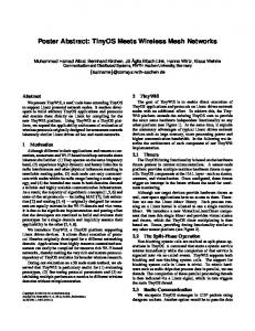
Figure 3.1. An example of ODMRP-HT mesh creation for a multicast group with 2 sources (S1 , S2 ) and 6 receivers (R1 , . . . , R6 ). The label on each link represents the value of the link’s SPP metric.
routes based on a link-quality metric, and (2) ODMRP-HT uses a weighted flood suppression mechanism to flood Join Query messages instead of using a basic flood suppression. As required by the link-quality metric, each node measures the quality of the links from its neighbors to itself, based on the periodic probes sent by its neighbors. The Join Query message is flooded periodically by a source S and contains a route cost field which accumulates the metric for the route on which the message travelled. Upon receiving a Join Query, a node updates the route cost field by accumulating the metric of the last link travelled by the message. Because different paths may have different metrics, Join Query messages are flooded using a weighted flood suppression mechanism, in which a node processes flood duplicates for a fixed interval of time and rebroadcasts flood messages that advertise a better metric (indicated by the route cost field)2 . Each node also records the node from which it received the Join Query with the best quality metric as its upstream node for the source S. After waiting for a fixed interval of time, during which it may receive several Join Query packets that contain different route metrics, a multicast receiver records Several studies [27, 30] show that the overhead caused by rebroadcasting some of the flood packets is reasonable, validating the effectiveness of this weighted flood suppression strategy. 2
18 as its upstream for source S the neighbor that advertised the Join Query with the best metric. Just like in ODMRP, the receiver then constructs a Join Reply packet, which will be forwarded towards the source on the optimal path as defined by the metric and will activate the nodes on this path as part of the Forwarding Group. In Figure 3.1 we give an example of how ODMRP-HT selects the mesh of nodes in the Forwarding Group based on the SPP link-quality metric.
3.2 Attacks against High-Throughput Multicast In this section, we present attacks against high-throughput multicast protocols. In particular, we focus on attacks that exploit vulnerabilities introduced by the use of high-throughput metrics. These attacks require little resource from the attacker, but can cause severe damage to the performance of the multicast protocol. We first present the adversarial model, followed by the details of the attacks.
3.2.1 Adversarial Model and Goal We consider the adversarial model as described in Chapter 2. In particular, malicious nodes may exhibit Byzantine behavior, either alone or in collusion with other malicious nodes. We refer to any arbitrary action by authenticated nodes deviating from protocol specification as Byzantine behavior, and to such an adversary as a Byzantine adversary. Examples of Byzantine behavior include: Dropping, injecting, modifying, replaying, or rushing packets, and creating wormholes. We consider attacks that aim to cause denial-of-service (DoS) on the multicast data delivery, and do not consider other attack goals such as traffic analysis, eavesdropping, or selfish attacks where attackers refuse to participate in the multicast protocol for other nodes. As presented in Chapter 2, we assume that adversaries do not have control on the physical or MAC layers, which can be protected with with jamming-resilient techniques such as frequency hopping and a more resilient MAC (e.g., [31]). We
19 also do not consider the Sybil attack, which can be addressed using techniques such as [32, 33], complementary to our protocol.
3.2.2 Attacks In general, the attacker can achieve the goal of disrupting the multicast data delivery by either exhausting network resource (resource consumption attacks), by causing incorrect mesh establishment (mesh structure attacks), or by dropping packets (packet dropping attacks). The packet dropping attack is straightforward: The attacker node on the data delivery path simply drops data packets instead of forwarding them. We describe next resource consumption and mesh structure attacks.
Resource consumption attacks ODMRP-HT floods Join Query messages in the entire network, allowing an attacker to inject either spoofed or its own legitimate Join Query messages at a high frequency to cause frequent network-wide flooding. The attacker can also activate many unnecessary data paths by sending many Join Reply messages to cause unnecessary data packet forwarding. Finally, the attacker can inject invalid data packets to be forwarded in the network. If the attackers are insider nodes, an effective attack is to establish a legitimate group session with high data rate in order to deprive the network resource from honest nodes. Addressing such an attack requires admission control mechanisms (e.g. [34]), which can limit the admission and duration of such groups. However, such mechanisms are out of the scope of this paper and are not considered further.
20 Mesh structure attacks Mesh structure attacks disrupt the correct establishment of the mesh structure in order to disrupt the data delivery paths. These attacks can be mounted by malicious manipulation of the Join Query and Join Reply messages. For the Join Query messages, the attacker can spoof the source node and inject invalid Join Query messages, which can cause paths to be built toward the attacker node instead of the correct source node. The attackers may also act in a selfish manner by dropping Join Query messages, which allows them to avoid participation in the multicast protocol. Since Join Query messages are flooded in the network, unless the attacker nodes form a vertex cut in the network, they cannot prevent legitimate nodes from receiving Join Query messages. Finally, the attacker may also modify the accumulated path metrics in the Join Query messages incorrectly. Such metric manipulation attacks can pose a severe threat to the correctness of path establishment, and are discussed in more detail in the next section. For the Join Reply messages, the attacker can drop Join Reply messages to cause its downstream nodes to be detached from the multicast mesh. The attacker can also forward Join Reply to an incorrect next hop node to cause an incorrect path being built. In many of the above attacks the power of the attacker relates directly to its ability to control the mesh structure and to be selected on paths. For example, if the attacker is on the path of many receivers, the attacker can affect many receivers by dropping the Join Reply messages or the data packets. Traditionally, such ability is achieved via wireless-specific attacks such as rushing and wormholes. The use of high-throughput metrics gives attackers additional opportunities to manipulate the mesh structure by manipulating the routing metric. Rushing and wormholes are general attacks against wireless routing protocols that have been studied extensively [9, 10, 35, 36]. We focus below on metric manipulation attacks, which require only little effort to execute, yet
21 are extremely detrimental to the protocol performance; such attacks have not been studied before.
3.2.3 Metric Manipulation Attacks As discussed in Section 3.1, multicast protocols using high-throughput metrics prefer paths to the source that are perceived as having high-quality, while trying to avoid low-quality paths. Thus, a good strategy for an attacker to increase its chances of being selected in the Forwarding Group is to advertise artificially good metrics for routes to the source. The use of high-throughput metrics requires each node to collect local information about its adjacent links based on periodic probes from its neighbors. This local information is accumulated in Join Query packets and propagated in the network, allowing nodes to obtain global information about the quality of the routes from the source. Adversaries can execute two types of metric manipulation attacks: local metric manipulation (LMM) and global metric manipulation (GMM). These attacks are Byzantine in nature, as they are conducted by nodes that have the credentials to participate in the routing protocol, but are under adversarial control. Local Metric Manipulation (LMM) Attacks. An adversarial node artificially increases the quality of its adjacent links, distorting the neighbors’ perception about these links. The falsely advertised “high-quality” links will be preferred and malicious nodes have better chances to be included on routes. A node can claim a false value for the quality of the links towards itself. In Figure 3.2 a malicious node C1 claims that SPPB1 →C1 = 0.9 instead of the correct metric of 0.6. Thus, C1 accumulates a false local metric for the link B1 → C1 and advertises to R the metric SPPS→C1 = 0.9 instead of the correct metric SPPS→C1 = 0.6. The route S-A1 -B1 -C1 -R will be chosen over the correct route S-A3 -B3 -C3 -R. Global Metric Manipulation (GMM) Attacks. In a GMM attack, a malicious node arbitrarily changes the value of the route metric accumulated in the flood
22
A1
1
B1
1
S
1
A2
0.5
B2
0.6 0.9
0.5
C1 0.9
C2 0.9
1
A3
1
B3
0.8
0.8 0.8
R
0.8
C3 0.8
Figure 3.2. Metric manipulation attack during the propagation of the flood packet from the source S to receiver R. A label above a link is the link’s real SPP metric; a label below a link is the link’s metric falsely claimed by a node executing a LMM attack; a label below a node is the accumulated route metric advertised by the node.
packet, before rebroadcasting this packet. A GMM attack allows a node to manipulate not only its own contribution to the path metric, but also the contributions of previous nodes that were accumulated in the path metric. For example, in Figure 3.2 attacker C2 should advertise a route metric of 0.25, but instead advertises a route metric of 0.9 to node R. This causes the route S-A2 -B2 -C2 -R to be selected over the correct route S-A3 -B3 -C3 -R.
3.2.4 Impact of Metric Manipulation Attacks on Routing The danger of metric manipulation attacks comes from the epidemic attack propagation due to the epidemic nature of metric derivation. As a result, even a few number of attackers can “poison” the metrics of many nodes in the network and create powerful blackholes that attract and control the traffic to many receivers. We exemplify these effects with the scenario in Figure 3.3. When no attackers are present (Figure 3.3(a)), nodes B, C and D are activated as part of the Forwarding Group. Consider that node A executes a metric manipu-
23
S
0.9
D
0.9
0.7 0.8
0.8 0.9
E
0.8
F
0.9
S
0.9
D
0.9
C
A
0.9
0.9
0.9
0.9 0.9
H
R1
0.8 0.9
B 0.9 0.9
0.9
0.7 0.8
G
0.9
E
R2 0.9
(a) benign case
0.8
F
0.9
0.9
C
0.9
0.9
0.9 0.9
H
R1
A
B
0.9
0.9 0.9 0.9
G
R2 0.9
(b) attack case
Figure 3.3. Metric manipulation attack in a network with one source (S), two receivers (R1 , R2 ) and one attacker (A). The label on each link represents the value of the link’s SPP metric.
lation attack (Figure 3.3(b)): Upon receiving the Join Query, node A changes the metric and advertises a perfect metric with value 1. Consequently, node C derives an incorrect metric of 0.9, and then propagates it to its neighbors, causing them to derive an incorrect metric as well. Both receivers R1 and R2 are also “attracted” to the attacker and only nodes B and C will be selected as part of the Forwarding Group. The net effect is that both R1 and R2 are disconnected from the source. Besides distorting path establishment for data delivery, a severe side effect of the attack is that it introduces a significant challenge for attack recovery. As the epidemic nature of metric poisoning causes the metric of many nodes to be incorrect, these metrics cannot be used for attack recovery even after the attacker is identified. Instead, one has to either resort to a fallback procedure not using the metric or refresh the metric of all the nodes in the network in a trustworthy manner before recovery.
3.3 Secure High-Throughput Multicast Routing In this section, we present our secure multicast routing protocol, S-ODMRP, with a novel defense scheme RateGuard to accommodate high-throughput metrics.
24 3.3.1 Authentication Framework We assume that each user authorized to be part of the mesh network has a pair of public and private keys and a client certificate that binds its public key to a unique user identifier. This defends against external attacks from nodes that are not part of the network. We assume source data is authenticated, so that receivers can distinguish authentic data from spurious data. Efficient source data authentication can be achieved with existing schemes such as TESLA [37]. Finally, we assume the existence of a secure neighbor discovery scheme [38].
3.3.2 S-ODMRP Overview S-ODMRP ensures the delivery of data from the source to the multicast receivers even in the presence of Byzantine attackers, as long as the receivers are reachable through non-adversarial paths. To achieve this goal, S-ODMRP uses a combination of authentication and rate limiting techniques against resource consumption attacks and a novel technique, RateGuard, against the more challenging packet dropping and mesh structure attacks, including metric manipulations and Join Reply dropping. S-ODMRP uses source message authentication to avoid processing bogus messages injected by the attacker. This eliminates a large class of attacks, including outsider attacks, message spoofing and modification attacks targeting Join Query and Join Reply messages, and the injection of corrupted data packets. Even with message authentication, an insider attacker can still mount the resource consumption attack by flooding Join Query messages frequently with itself as the source. Such an attack can be countered by rate limiting, for example, a honest node only forwards Join Query messages for a source node up to a maximum frequency. To address the resource consumption attack in which the attacker activates many unnecessary data delivery paths by injecting many Join Reply messages, we can limit to at most one the number of Join Reply messages a node may send in one round. Each node monitors the number of different signed Join Reply messages
25 that originate from its neighbors. If a node is observed to have broadcast two or more different signed Join Reply messages, then punitive actions can be taken against the node (e.g., isolation). The attacks on the mesh structure and packet dropping attacks are much more challenging to defend against, particularly in the context of high-throughput metrics. In the following, we focus on defending against these attacks. We will first present the high level overview of our defense scheme, RateGuard, and then present the details of S-ODMRP with the RateGuard scheme.
3.3.3 RateGuard Overview RateGuard relies on the observation that regardless of the attack strategy, either by dropping Join Reply, metric manipulations, or by dropping packets, attackers do not affect the multicast protocol unless they cause a drop in the packet delivery ratio (PDR). We adopt a reactive approach in which attacker nodes are detected through a measurement-based detection protocol component, and then isolated through an accusation-based reaction protocol component. Next we describe these two components. Measurement-based attack detection. Whether by packet dropping alone or by combining it with with metric manipulation to attract routes, the effect of an attack is that data is not delivered at a rate consistent with the advertised path quality. We propose a generic attack detection strategy that relies on the ability of honest nodes to detect the discrepancy between the expected PDR (ePDR) and the perceived PDR (pPDR). A node can estimate the ePDR of a route from the value of the metric for that route3 ; the node can determine the pPDR for a route by measuring the rate at which it receives data packets from its upstream on that route4 . For the SPP metric, a route’s ePDR is equal to the route’s metric. Source data authentication allows nodes to distinguish authentic packets from spurious ones and only authentic packets are counted towards pPDR. 3 4
26 Both Forwarding Group nodes and receiver nodes monitor the pPDR of their upstream node. If ePDR−pPDR for a route becomes larger than a detection threshold δ, then nodes suspect that the route is under attack because the route failed to deliver data at a rate consistent with its claimed quality5 . Accusation-based attack reaction. We use a controlled-accusation mechanism in which a node, on detecting malicious behavior, temporarily accuses the suspected node by flooding in the network an Accusation message containing its own identity (the accuser node) and the identity of the accused node, as well as the duration of the accusation. As long as the accusation is valid, metrics advertised by an accused node will be ignored and the node will not be selected as part of the Forwarding Group. This strategy also successfully handles attacks against path establishment. From the downstream node point of view, the dropping of a Join Reply message causes exactly the same effect as the attacker dropping all data packets, thus the downstream nodes will react and accuse the attacker. To prevent the abuse of the accusation mechanism by attackers, a node is not allowed to issue a new accusation before its previously issued accusation expires. Accused nodes can still act as receivers even though they are excluded from the Forwarding Group. We use a temporary accusation strategy to cope with transient network variations: The accusation duration is calculated to be proportional to the observed discrepancy between ePDR and pPDR, so that accusations caused by metric inflation and malicious data dropping last longer, while accusations caused by transient network variations last shorter. Finally, to address the metric poisoning effect caused by metric manipulation attacks, the metric in the entire network is refreshed shortly after attack detection. In S-ODMRP, the metric refreshment is achieved automatically through the periodic Join Query messages. Note that the rate inconsistency may also be caused by natural link quality variations. We do not differentiate between losses caused by adversarial behavior and natural link variations because lossy links must also be avoided in order to maintain a good performance level. 5
27 Sign(m): sign message m using this node’s private key Verify(n id, sig): verify the signature sig using node n id’s public key and exit the procedure if the verification fails Start timer(timer, t): start timer timer with timeout t Refresh timer(timer, t): if timer is not active, then call Start timer(timer, t); otherwise, set timeout of timer to t Broadcast(m): broadcast message m one hop Flood(m): flood message m in the entire network Send message(m, n id): reliably send message m to neighbor n id Link metric(n id): return the measured link metric to neighbor n id Get best metric(query set): return the best metric of all queries in the set query set, regardless of accusation status Get neighbor best metric(query set): return the neighbor that has the best metric in the set query set, regardless of accusation status Figure 3.4. Basic procedures used in the S-ODMRP protocol description
3.3.4 S-ODMRP Detailed Description To describe S-ODMRP in detail, we use the list of procedures described in Figure 3.4. For simplicity, we limit the description to one multicast group and one multicast source. However, the scheme can easily be extended to multicast groups with multiple sources.
Mesh Creation S-ODMRP mesh creation follows the same pattern of ODMRP-HT presented in Section 3.1.2. As described in Algorithm 1, the source node S periodically broadcasts to the entire network a Join Query message in order to refresh the membership information and to update the routes (Lines 1-5). The Join Query message is signed by S and is propagated using a weighted flood suppression mechanism. Nodes only process Join Query messages that have valid signatures (Line 8) and that are received from nodes not currently accused (indicated by an Accusation List maintained by each node) (Lines 18-19). Nodes record the upstream node and the metric
28 corresponding to the route with the best metric as best upstream and best metric (Line 23). The Join Reply messages are then sent from receivers back to S along optimal paths as defined by the high-throughput metric, leading to the creation of the Forwarding Group (the multicast mesh) for data delivery (Lines 28-29). After sending a Join Reply to its best upstream, a node starts to monitor the PDR from its best upstream in order to measure its perceived PDR (pPDR) (Line 38). To address attackers that strategically accuse certain nodes in order to disconnect the network, we make one exception from the rule that only non-accused nodes are included in the Forwarding Group: If the best metric is advertised by an accused neighbor, a node also activates this neighbor (by sending a Join Reply) in addition to the best non-accused neighbor (Lines 39-39). This ensures that good paths are still utilized, even if honest nodes on these paths are falsely accused. In Section 3.5.5, we show that this strategy only adds a very low overhead.
Attack Detection As described in the protocol overview, we detect attacks using a measurementbased mechanism, where each Forwarding Group and receiver node continuously monitors the discrepancy between ePDR and pPDR and flags an attack if ePDR − pPDR > δ. The most straightforward method for estimating pPDR is to use a sliding window method, with pPDR calculated as pPDR = r/w, where r is the number of packets received in the window and w is the number of packets sent by the source (derived from packet sequence numbers) in that window. Albeit being simple, this method is sensitive to bursty packet loss. In addition, this approach requires a node to wait until at least w packets are sent in a round before being able to make any decision. Therefore, setting w too large causes delay in making decisions, whereas setting w too small results in inaccurate pPDR estimation and hence more frequent false positives.
29
Algorithm 1: Mesh creation algorithm Executed at the source node to initiate a new Join Query message: 1: create a Join Query message q 2: q.source = source id; q.from = source id 3: q.path metric = 1; q.seq = join seq 4: join seq + + 5: Sign(q); Broadcast(q) Executed at a node upon receipt of a Join Query message q: 6: if (latest received join seq > q.seq) then 7: return // ignore old queries 8: Verify(q.from, q.sig) 9: get new query = FALSE 10: if (latest received join seq < q.seq) then 11: // get a new (non-duplicate) query 12: latest received join seq = q.seq 13: best metric = 0 14: best upstream = INVALID NODE 15: fastest upstream = q.from // for fallback recovery 16: get new query = TRUE 17: received queries.insert(q) // store the query 18: if (accusation list.contains accused node(q.from)) then 19: q.path metric = 0 20: else 21: q.path metric = q.path metric × Link metric(q.from) 22: if (get new query OR q.path metric > best metric) then 23: best upstream = q.from; best metric = q.path metric; 24: q.from = node id 25: Sign(q); Broadcast(q) 26: if (get new query AND is receiver) then 27: Start timer(reply timer, REPLY TIMEOUT) Executed at a node upon timeout of reply timer: 28: Send reply() Executed at a node upon receipt of a Join Reply message r: 29: if (latest received reply seq < r.seq) then 30: latest received reply seq = r.seq 31: Refresh timer(FG timer, FG TIMEOUT) 32: if (not is receiver) then 33: Send reply() Send reply() 34: create a Join Reply message r 35: r.seq = latest received join seq 36: Send message(r, best upstream) 37: if (best metric > 0) then 38: start monitoring the PDR of best upstream 39: if (Get best metric(received queries) > best metric) then 40: // Activate the accused neighbor with best metric 41: Send message(r, Get neighbor best metric(received queries)) 42: received queries.clear() // purge stored queries
30 In general, it is difficult to determine the optimal value for w, as it depends on the network conditions and the specific position of a node. To avoid these shortcomings, we propose an efficient statistical-based estimation method for pPDR that naturally adapts to the network environment of each node. The main idea is to use the Wilson estimate [39] to determine a confidence interval for pPDR, instead of trying to obtain a single estimated value. Let m be the number of packets received by a node and n be the number of packets sent by the source in the same time period, which can be derived from packet sequence numbers. The Wilson estimate requires that n ≥ 5 [39], so whenever n ≥ 5, we can obtain a confidence interval for pPDR as (ˆ p − e, pˆ + e), where m+2 pˆ = and e = z n+4
�
pˆ(1 − pˆ) . n+4
We assign z = 1.96 to obtain the commonly used confidence level of 95%. An attack is detected if the upper bound of the confidence interval for pPDR is less than the estimated PDR even after accounting for normal network variations, i.e., if: pˆ + e < ePDR − δ, where δ is the estimated PDR discrepancy under normal network conditions. In this method, the exact number of packets required for attack detection naturally adapts to the path quality and the severity of the attack. In addition, there is a precise level of confidence on the accuracy of our estimation. This method has the advantage that it applies for both constant rate and variable rate data sources. Addressing silent periods. If a node fails to receive any data packets in a round, the above method will be not able to compute the confidence interval of pPDR for its upstream node, since the value of n is derived from sequence numbers contained in received packets. We address this issue by including the current data sequence number in Join Query packets, which are periodically flooded in the network. Thus, unless a node does not have any adversarial-free path to the source, it can always obtain the current data sequence number and compute the pPDR confidence interval to detect attacks.
31 Attack Reaction To isolate attackers, our protocol uses a controlled-accusation mechanism which consists of three components, staggered reaction timeout, accusation message propagation and handling, and recovery message propagation and handling. As described in Algorithm 2, when a node detects attack behavior, it starts a React Timer with timeout value β(1 − ePDR), where β is a system parameter that determines the maximum timeout for reaction timer (Line 1). Since ePDR decreases monotonically along a multicast data path, nodes farther away from the source will have a larger timeout value for the React Timer. This staggered timeout technique ensures nodes immediately below the attacker will take action first, before any of their downstream nodes mistakenly accuse their upstream node. When the React Timer of a node N expires, N accuses its best upstream node and cancels the React Timer at its downstream nodes with the following actions: • Create, sign, and flood an Accusation message in the network, which contains N ’s identity (the accuser node) and the identity of N ’s best upstream node (the accused node). The message also contains a value accusation time = α(ePDR − pPDR), indicating the amount of time the accusation lasts (Lines 8-13). α is a tunable system parameter that determines the severity of attack punishment. • Create, sign, and send to its downstream nodes a Recovery message, which contains the Accusation message (Lines 15-18). This message serves the role of canceling the React Timer of nodes in N ’s subtree and activating the fallback procedure at the receivers in N ’s subtree (see Section 3.3.4). Upon receipt of an Accusation message, a node checks if it does not have an unexpired accusation from the same accuser node and verifies the signature on the message. This enforces our limited accusation mechanism, which allows nodes to only have one active accusation at a time. If both checks pass, the node adds a corresponding entry to its Accusation List (Lines 20-23). Accusations are removed from the Accusation List after the accusation time has elapsed.
32 Algorithm 2: Attack reaction algorithm On detecting a discrepancy between ePDR and pPDR: 1: Start timer(React Timer, β(1 − ePDR) Executed at node on timeout of React Timer: 2: if (is receiver) then 3: create salvage message ss // fallback 4: Send message(ss, fastest upstream) 5: if (accusation list.contains accuser node(node id)) then 6: return // each node can only accuse once 7: // create and flood accusation message 8: create accusation message acc 9: acc.accused = best upstream 10: acc.accuser = node id 11: acc.accusation time = α(ePDR − pPDR) 12: accusation list.add(acc) 13: Sign(acc); Broadcast(acc) 14: // send recovery message to the subtree 15: create recovery message rr 16: rr.accusation = acc 17: Sign(rr) 18: for each downstream node d do 19: Send message(rr, d)
Executed at a node on receipt of an accusation message acc: 20: if (accusation list.contains accuser node(acc.accuser)) then 21: return // only allow one accusation from a node at a time 22: Verify(acc.accuser, acc.sig) 23: accusation list.add(acc) 24: Broadcast(acc) Executed at a node on receipt of a recovery message rr: 25: if (handled recovery messages.contains(rr)) then 26: return // ignore duplicate recovery 27: if (accusation list.contains accuser node(rr.acc.accuser) OR rr.acc.accusation time < α(ePDR − pPDR)) then 28: return // ignore recovery mesage if the accuser has an unexpired accusation or if the accused time is inconsistent 29: Verify(rr) 30: handled recovery messages.insert(rr) 31: if (React Timer is active) then 32: cancel React Timer 33: for each downstream node d do 34: Send message(rr, d) 35: if (is receiver) then 36: create salvage message ss // fallback 37: Send message(ss, fastest upstream) Executed at a node on receipt of a salvage message ss: 38: Refresh timer(FG timer, FG TIMEOUT) 39: Send message(ss, fastest upstream)
33 Upon the receipt of a Recovery message rr from its best upstream node, a Forwarding Group node N checks if it does not have an unexpired accusation from the same accuser node and verifies the signature on the message. In addition, the node also checks that the accusation time in the message is at least as much as its own observed discrepancy (the ePDR − pPDR value) (Lines 27-27). This prevents attackers who cause a large PDR drop from bypassing our defense by accusing its upstream node only for a short amount of time. If all checks pass, it cancels its pending React Timer, forwards rr to its downstream nodes (Lines 31-33), and if it is a receiver, activates the recovery procedure (Lines 35-35) (see below). Avoiding redundant accusations. Typically, an attacker node will attract many honest neighbor nodes to connect to it. In order to avoid all the neighboring nodes accusing the same attacker node and losing their accusing ability, we require each of the neighboring nodes to add a random jitter before flooding its accusation message. If a neighboring node receives an accusation message accusing the same node it is about to accuse, it aborts its pending accusation. If the node is required to send a Recovery message to its downstream, it includes the received accusation message in Recovery instead of its own accusation message.
Fallback Recovery The accusation mechanism ensures that when the metric is refreshed in the round after the attack detection, the accused nodes are isolated. However, during the round when an attack is detected, the receiver nodes in the subtree of the attacker need to find alternative routes to “salvage” data for the rest of the round. As shown in Section 3.2.3, a side effect of metric manipulation attacks is metric poisoning, which prevents recovery by relying on the metrics in the current round. We address this inability by falling back to the fastest route for routing during the remainder of the round6 . Specifically, during the Join Query flooding, besides recording the The strategy is not attack-proof, as the fastest route may include malicious nodes. However, since the route is only used for the remainder of the round, we prefer to use an efficient procedure than 6
34 best upstream node, each node also records the upstream for the fastest route as fastest upstream (Algorithm 1, line 15). To recover from an attack, a receiver sends a special Join Reply message (a salvage message) to its fastest upstream node (Algorithm 2, lines 2-2 and 35-35). Each node on the fastest route forwards the special Join Reply message to their fastest upstream node and becomes part of the Forwarding Group (Algorithm 2, lines 38-39).
3.3.5 Impact of False Positives Even though our defense scheme takes into account normal network variations with the parameter δ, it is still possible that some honest nodes are mistakenly accused. We argue that such false positive accusations have little impact on the performance of the system for two main reasons. First, under most cases honest nodes cause only a small discrepancy on the PDR, thus even if mistakenly accused, their accusation duration is relatively short. Second, for most receivers there are redundant paths to the source. Thus, even if some honest nodes are wrongly accused, affected receiver nodes can obtain a similar performance by using nearby alternate routes.
3.3.6 Practical Implementation Issues Parameter Selection S-ODMRP has three tunable parameters, the attack detection threshold δ, the coefficient for accusation duration α, and the coefficient for React Timer β. The selection of δ trades off tolerance to normal network variations with sensitivity of the scheme to attacks. A larger value for δ reduces false positives of accusing honest nodes, however, it also allows attackers to inflict more impact without being detected. An optimal value for δ is the estimated normal network variation, i.e. the sum of the PDR discrepancy under normal network conditions and the error in estimating to find attacker-free paths, which is itself a challenging task and requires expensive protocols [25]. We further discuss in Section 3.4.1 and 3.4.2 the impact of attacks against the recovery phase.
35 ePDR from the advertised metric. Our experiments show that a typical value for δ is 20%. The value for α trades off the effectiveness of the scheme in isolating attacker nodes and the severity of isolating honest nodes due to false positives. In a stable network where the number of false positives is small, or in a dense network where the impact of false positives is small due to path redundancy, it is advisable to have a large value for α in order to reduce the impact of attacks. In Section 3.4.1, we give lower bounds for α in order for the scheme to bound the impact of attacks effectively. The value for β trades off the attack reaction delay and the effectiveness of the staggered reaction timeout technique for preventing honest nodes from mistakenly accusing each other. A smaller β results in quicker attack reaction, however, it also results in a smaller difference in the reaction timeout value for consecutive nodes on a path, increasing the chance of honest nodes being mistakenly accused. In our experiments, we find β = 20ms achieves a good balance between these two effects.
Ensuring Staggered Timeouts for Reaction Timers To avoid honest nodes mistakenly accusing each other, it is critical that we ensure the React Timer at a downstream node does not expire before the node receives a recovery message from its upstream node. Denote the link latency as t, and the estimated PDR of two consecutive nodes on a path as ePDR1 and ePDR2 . The React Timer timeout value for the two nodes is T O1 = β(1 − ePDR1 ) and T O2 = β(1 − ePDR2 ). We need to ensure T O2 − T O1 > t, that is, β(1 − ePDR2 ) − β(1 − ePDR1 ) > t, hence ePDR2 < ePDR1 − t/β. Therefore, to ensure staggered reaction timeout, we require a node artificially decreases its advertised metric if necessary so that its ePDR is at least t/β smaller than the ePDR of its upstream node.
36 3.4 S-ODMRP Security Analysis In this section, we analyze the security of the S-ODMRP protocol and establish bounds on the attack impact and on protocol resilience to various types of attacks.
3.4.1 Attack Impact We upper bound the attack impact on the throughput of S-ODMRP. We first give a precise definition of the attack impact. We then present two theorems that upper bound the attack impact and discuss their practical implications. Let N denote the network of interest with k attacker nodes. We define N � as the exact same network as N , except that all the attacker nodes are removed. For a given � non-attacker receiver node R, let rR (t) and rR (t) be the perceived PDR of R at time
t in network N and N � , respectively. We define IR , the attack impact on a node R, as 1 IR = t1 − t0
�
t1
t0
� (rR (t) − rR (t))dt,
where t0 and t1 are the start and end times for the interval of interest. Intuitively, the attack impact is the average PDR degradation caused by the presence of attackers over time compared to a network with no attackers. Alternatively, the attack impact captures the discrepancy between a given defense scheme and a hypothetical perfect defense scheme where all the attackers nodes are perfectly isolated. Recall that δ denotes the attack detection threshold and α denotes the accusation duration coefficient. Also, recall that a round is an interval between two consecutive mesh creation events. We use λ to denote the time duration of a round. In the following, we show two theorems that bound the attack impact of metric manipulation attackers (colluding or individual) on any non-attacker receiver node in the presence of our defense mechanisms.
37 Theorem 3.4.1 In a network with k metric manipulation attackers, for any α ≥
kλ , δ2
the attack impact on any non-attacker receiver node in S-ODMRP is upper bounded by δ during any time interval of duration T � α. Implications of Theorem 3.4.1. According to Theorem 3.4.1 for large enough α, the impact of metric manipulation attacks is bounded by the attack detection threshold δ. For example, with δ = 20%, round duration of λ = 3 seconds, and a total of 10 attackers, according to Theorem 3.4.1, we can set α ≥ 750 seconds to ensure the attack impact on any non-attacker receiver node is bounded by δ. Theorem 3.4.1 assumes the attacker nodes can coordinate perfectly and completely disrupt the fallback procedure, thus it gives an upper bound on the impact of the attack. Theorem 3.4.2 In a network with k metric manipulation attackers, if S-ODMRP uses a fallback procedure that restores the PDR to the same level as in a benign network, then for any α ≥
kλ , δ
the attack impact on any non-attacker receiver node is
upper bounded by δ during any time interval of duration T � α. Implications of Theorem 3.4.2. In Theorem 3.4.2, we see that if we assume the ideal case where the fallback procedure is always able to restore the data rate to the normal level, then we can bound the attack impact under δ with a much smaller value for the accusation duration α. For example, with the same settings of δ and λ as above, we only need to set α ≥ 150 seconds. The fallback recovery procedure uses fastest paths to recover data after attack detection. Assuming resilience against rushing attacks, the attackers cannot attract the recovery paths toward incorrect directions. Furthermore, the broadcast nature of wireless transmission and the mesh nature of ODMRP can also tolerate occasional attackers on the data forwarding paths. Hence, in a relatively dense network where there are many possible paths from receivers to the source, most receivers are able to restore the data rate to a level similar with the fallback recovery phase (this is
38 also confirmed by our experiments in Section 3.5). Therefore, compared to Theorem 3.4.1, Theorem 3.4.2 is a closer approximation to reality: We only need to set α to be slightly larger (e.g., 250 seconds in our experiments) than the value derived from Theorem 3.4.2 to bound the attack impact under the estimated normal network variations. Proofs of Theorem 3.4.1 and 3.4.2. To prove these two theorems, we first introduce some additional notations and two lemmas. We label the start of the time duration of interest of T as t0 . Without loss of generality, let time ti and ti+1 be the start and end times of round i, for i ≥ 0. Since a node only estimates its metric at the beginning of a round, let mB (i) and m�B (i) be the estimated PDR from metric for node B in round i in network N and in N � , respectively. We use r¯B (i) and ∆B (i) to denote the average perceived PDR and average PDR discrepancy of node B in round i �t in network N , respectively, that is r¯B (i) = λ1 tii+1 rB (t)dt and ∆B (i) = mB (i) − r¯B (i).
� Similarly, we define r¯B (i) and ∆�B (i) for network N � . With a slight abuse of notation,
we denote the attack impact on node B in round i as IB (i), that is, IB (i) = IB (ti , ti+1 ). � It is easy to see that IB (i) = r¯B (i) − r¯B (i).
For simplicity, we assume that the network is stable and the PDR estimation from � the metric is accurate. Hence, for benign network N � , we have m�B (i) and r¯B (i) are � � constant and m�B (i) = r¯B (i) for all i. Thus, without ambiguity, we use r¯B to denote
both the estimated and perceived PDR at node B in network N � . Thus, we have � IB (i) = r¯B − r¯B (i).
We also discount any physical layer effects (e.g., interference), which means that mU (i) ≥ rU� for any node U , since additional attacker nodes cannot decrease the metric derived by honest nodes. Lemma 1 For any round i and any non-attacker node B, we have IB (i) ≤ ∆B (i).
39 Proof In order for an attack to have any impact on R, it must be the case that � mB (i) ≥ rB , since otherwise attacker nodes will not be selected on the path. There-
fore, � IB (i) = rB − r¯B (i) ≤ mB (i) − r¯B (i) = ∆B (i).
� Intuitively, Lemma 1 says that the attack impact of any node is always upper bounded by its observed PDR discrepancy. Lemma 2 For any consecutive sequence of time intervals (t0 , t1 ), · · · , (tk−1 , tk ) and a non-attacker node B, if IB (ti , ti+1 ) ≤ d for all 0 ≤ i ≤ k − 1, then IB (t0 , tk ) ≤ d. Proof This is immediate from the definition of attack impact.
�
Proof of Theorem 3.4.1: For ease of exposition, we first analyze the single attacker case, followed by the multiple attackers case. For the single attacker case, let A be the attacker node in network N and let R be a non-attacker receiver node that is downstream from A. Let node B be the immediate downstream of node A on the path from A to R. Let pBR denote the path PDR between B and R. Since there is no attacker between B and R, we have � � rR = rB · pBR and rR = rB · pBR . Thus, � t1 1 IR = (r� (t) − rR (t))dt t1 − t0 t0 R � t1 1 � = (rB (t) · pBR − rB (t) · pBR )dt t1 − t0 t0 � t1 pBR = (r� (t) − rB (t))dt t1 − t0 t0 B
= IB · pBR ≤ IB Therefore, we only need to show IB ≤ δ. We classify rounds into two categories, Category A for rounds in which the attacker is not detected, and Category B for rounds in which the attacker is detected or
40 isolated. An attack in a Category A round i implies, by definition, that the attacker is not detected, i.e., it drops data below the δ threshold: ∆B (i) < δ. By Lemma 1, we have IB (i) ≤ ∆B (i) ≤ δ. Let round a be the round in which the attack is detected and let w be the discrepancy observed at node B when the attack is detected. Then our protocol ensures that w ≥ δ and that node B accuses and isolates node A for time αw ≥ αδ. If we denote the time when the attacker recovers from the accusation as tr , then tr − ta ≥ αw. Therefore, the attack impact on node B from time ta to time tr is: � ta+1 � (rB − rB (t))dt λ λ IB (ta , tr ) = ta ≤ ≤ tr − ta αw αδ Hence, if α ≥
λ , δ2
we have IB (ta , tr ) ≤ δ. Therefore, by Lemma 2, we have IB (t0 , tr ) ≤
δ. Since the maximum accusation time is α, for any time interval with duration T � α, we have IR ≤ IB ≤ δ. For the case of multiple attackers, for rounds in Category A, where no attackers are detected, we also have IB (i) ≤ δ. For rounds in Category B, node B may switch to another attacker node in the round after detecting an attacker node, hence for a total of k attacker nodes, we have IR (ta , tr ) ≤ IB (ta , tr ) ≤ Hence, if α ≥
kλ , δ2
we have IR (ta , tr ) ≤ δ.
kλ kλ ≤ tr − ta αδ
✷
Proof of Theorem 3.4.2: In the proof of Theorem 3.4.1, we assume a node has perfect path quality in the benign network, whereas the node has zero PDR in the round when the attacker is detected. If the fallback procedure can restore the PDR to the level of the benign network, then the attack impact during that round is bounded by δ (because, once the discrepancy on the average PDR exceeds δ, the attack is detected and the node invokes the fallback procedure). Therefore, we can derive an upper bound for IR for rounds in Category B as follows: IR (ta , tr ) ≤ Hence, if α ≥
kλ , δ
kδλ kδλ kλ ≤ = tr − ta αδ α
then IR (ta , tr ) ≤ δ. Following a similar analysis as in Theorem 3.4.1,
we obtain that IR ≤ δ for any time interval of duration T � α.
✷
41 3.4.2 RateGuard Attack Resiliency We discuss the resilience of the RateGuard protocol to various types of attacks. In particular, the attacker may inject, modify, or drop accusation and recovery messages. Since both accusation and recovery messages are signed by the sender, the modification attack is prevented. We consider the other attacks as follows. Accusation message dropping. Since accusation messages are flooded in the network, unless the attacker nodes form a vertex-cut in the network, they cannot cause accusation messages to be missed by other nodes. False accusation attack. Our limited accusation mechanism restricts attackers to only have one active false accusation at any time. In addition, our technique of activating the neighbor advertising the best metric regardless of its accused status ensures that falsely accused nodes are also used in routing. This prevents attacker nodes from partitioning the network by strategically accusing certain honest nodes. Therefore, false accusation attacks only cause falsely accused nodes to be ignored in the metric propagation process. In a dense enough network, this only results in limited impact on the metric derived at each node, as each node typically has multiple disjoint paths with similar metrics to the source. Therefore, the overall impact of the false accusation attack is limited. Recovery message injection. Since a node ignores recovery message unless there is a corresponding accusation message, the one active accusation only policy also prevents the attacker from causing its downstream nodes to constantly resort to the fall-back procedures. Recovery message dropping. Dropping a recovery message will only cause the attacker node itself to be accused by its downstream honest node, because the downstream node does not cancel its reaction timer unless it receives a recovery message. Attacks on the fall-back procedure. Since we do not protect the fallback recovery phase, attackers that are selected as forwarders during the recovery phase
42 may drop packets without being punished. However, since the fallback recovery is only used to salvage data for the remaining of the current round, the impact of the attack is limited. As shown in Theorem 3.4.1, even if the attacker is able to completely block all packets to a node during the fallback recovery procedure, the average attack impact is still bounded by δ for sufficiently large values of α.
3.4.3 Limitations of S-ODMRP In S-ODMRP, a node is detected as an attacker only if the PDR drop caused by the node exceeds the threshold δ. Therefore, this leaves the room for an attacker to drop some amount of data below the threshold δ without being detected. Since the threshold δ models the normal PDR variation exhibited by legitimate nodes, it is impossible to distinguish such attackers from normal nodes. One may address this shortcoming with more accurate modeling of the behavior of normal nodes. For example, we can incorporate both the mean and the variance of PDR. Since we expect PDR to vary around its mean under normal network variations, a node whose PDR is constantly below its advertised value, even only for a small amount, can be seen as abnormal. We defer such enhancements as future work. S-ODMRP restricts a node to accuse at most one other node at a time. This implies that attacker nodes should be a minority in the network. Otherwise, some attacker nodes will be left unaccused and will be free to attract and deny service to many receivers through metric manipulation. It is extremely difficult to secure a network where the majority of nodes are insider attackers, and we do not address this scenario in this work.
3.5 Experimental Evaluation In this section, we demonstrate through experiments the vulnerability of metric enhanced multicast protocol by examining the impact of different attacks, and investigate the effectiveness of our defense mechanism and its associated overhead.
43 3.5.1 Experimental Methodology Simulation Setup. We implemented ODMRP-HT and S-ODMRP using the ODMRP version available in the Glomosim [40] simulator. Nodes were set to use 802.11 radios with 2 Mbps bandwidth and 250m nominal range. We simulate environments representative of mesh networks deployments by using the two-ray radio propagation model with the Rayleigh loss model, which models environments with large reflectors, e.g., trees and buildings, where the receiver is not in the line-of-sight of the sender. The network consists of 100 nodes randomly placed in a 1500m×1500m area. We randomly select 20 nodes as multicast group members and among the 20 members one node is randomly selected as the data source. Group members join the group at the beginning of the experiment. At second 100, the source starts to multicast data packets for 400 seconds at a rate of 20 packets per second, each packet of 512 bytes. When attackers are present, they are randomly selected among nodes that are not group members. For S-ODMRP, we use RSA signatures with 1024-bit keys, simulating delays to approximate the performance of a 1.3 GHz Intel Centrino processor. We empirically tune the threshold δ = 20% to accommodate random network variations in the simulated scenarios. The timeout for React Timer is set as 20(1 − ePDR) millisecond (i.e. β = 20), and the accusation time is set as 250(ePDR − pPDR) second (i.e. α = 250). Nodes use the statistical-based method described in Section 3.3.4 to determine their pPDR. We used the SPP high-throughput metric, configured with optimal parameters as recommended in [28]. Data points are averaged over 10 different random environments and over all group members. Attack Scenarios. We consider the following scenarios: • No-Attack: The attackers do not perform any action in the network. This represents the ideal case where the attackers are identified and completely isolated in
44 the network, and serves as the baseline for evaluating the impact of the attack and the performance of our defense. • Drop-Only: The attackers drop data packets, but participate in the protocol correctly otherwise. The attack has effect only when attackers are selected in the Forwarding Group. We use this scenario to demonstrate that metric manipulation amplifies data dropping attacks. • LMM-Drop: The attackers combine local metric manipulation (LMM) with the data dropping attack. The attackers conduct the LMM attack by re-advertising the same metric they received in Join Query, which is equivalent to making their link metric of the previous hop equal to 1 (best). • GMM-Drop: The attackers combine global metric manipulation (GMM) with the data dropping attack. The attackers conduct the GMM attack by re-advertising a metric of 1 (best) after receiving a Join Query. • False-Accusation: The attackers exploit our accusation mechanism by falsely accusing a random honest node at startup for the whole experiment period in order to reduce the PDR. We do not evaluate the attacks that aim to cause large bandwidth overhead through frequent flooding of accusation messages using false accusations. We can upper bound the frequency of the accusation message flooding from any attacker node to only once a few seconds by imposing a lower bound on the accusation timeout, thus the impact of the attack is limited. Metrics. We measure the performance of data delivery using the packet delivery ratio (PDR), defined as PDR = nr /ns , where nr is the average number of packets received by all receivers and ns is the number of packets sent by the source. We also measure the strength of the attacks using as metric the PDR decrease ratio (PDR-DR), defined as PDR-DR
=
PDRnoattack
− PDRattack
PDRnoattack
,
where PDRattack and PDRnoattack represent the PDR when the network is under attack and not under attack, respectively.
45 The overhead of our defense consists of three components, the control bandwidth overhead due to additional messages and larger message size (e.g., accusation messages, signatures on query messages), the computational overhead due to cryptographic operations, and the additional data packet transmissions caused by our protocol. We measure the control bandwidth overhead per node, defined as the total control overhead divided by the number of nodes. The computational overhead is measured as the number of signatures performed by each node per second. To measure redundant data packet transmissions, we define data packet transmission efficiency as the total number of data packets transmitted by all nodes in the network divided by the total number of data packets received by all receivers. Thus, data packet transmission efficiency captures the cost (number of data packet transmissions) per data packet received. mc:fig:attacks
3.5.2 Effectiveness of Metric Manipulation Attacks Figure 3.5(a) shows the impact of Drop-Only attack on the original ODMRP (not using high-throughput metric). The protocol is quite resilient to attacks, i.e., PDR decreases by only 15% for 20 attackers. This reflects the inherent resiliency of mesh based multicast protocols against packet dropping, as typically a node has multiple paths to receive the same packet. Figure 3.5(b) shows the PDR of the protocol when using a high-throughput metric (ODMRP-HT) under different types of attacks. We observe that with the Drop-Only attack, the PDR drops quickly to a level below the case when no high throughput metric is used. Thus, simple packet dropping completely nullifies the benefits of high throughput metrics. By manipulating the metrics as in LMM-Drop and GMMDrop, the attacker can inflict a much larger decrease in PDR. For example, the PDR decreases from 72% to only 25% for 10 attackers using GMM-Drop, in contrast to 55% for Drop-Only. Figure3.5(c) compares the impact of the attack in terms of the PDR
46
1
PDR
0.8 0.6 0.4 0.2 0
No-Attack Drop-Only 0
5
10
15
20
Number of attackers (a) Attacks on ODMRP 1
PDR
0.8 0.6 0.4 No-Attack Drop-Only LMM-Drop GMM-Drop
0.2 0 0
5
10
15
20
Number of attackers (b) Attacks on ODMRP-HT
PDR decrease ratio
1
GMM-Drop LMM-Drop Drop-Only
0.8 0.6 0.4 0.2 0
0
5
10
15
20
Number of attackers (c) Attack strength against ODMRP-HT
Figure 3.5. The effectiveness of metric attacks on ODMRP-HT
47 decrease ratio (PDR-DR). We see that metric manipulation significantly increases the attack strength. For example, with 10 attackers, the PDR-DR of GMM-Drop (68%) is more than double the PDR-DR of Drop-Only (32%). Thus, we conclude that metric manipulation attacks pose a severe threat to high-throughput protocols.
3.5.3 Effectiveness of the Defense In Figure 3.6 we show the effectiveness of our defense (S-ODMRP) against different types of attacks, compared to the insecure ODMRP-HT protocol. S-ODMRP suffers only a small PDR decrease relative to the baseline No-Attack case. For example, a total of 20 attackers causes a PDR drop of only 12%, considerably smaller than the case without defense, which shows a PDR decrease by as much as 55% in the GMMDrop attack. To rule out random factors, we performed a paired t-test [39] on the results showing that S-ODMRP improves the PDR for all attack types, with P-value less than 2.2 × 10⁻¹⁶ . For 10 attackers, S-ODMRP improves the PDR of ODMRP-HT for Drop-Only, LMM-Drop and GMM-Drop by at least 4.5%, 16.7%, 33%, with 95% confidence level. Thus, our defense is very effective against all the attacks. The small PDR decrease for S-ODMRP can be attributed to two main factors. First, common to all reactive schemes, attackers can cause some initial damage, before action is taken against them. Second, as the number of attackers increases, some receivers become completely isolated and are not able to receive data. Figure 3.6 also shows an interesting phenomenon: The PDR decrease of S-ODMRP is similar for all attacks, despite the varying strength of the attacks. This outcome reflects the design of our defense mechanism in which accusations last proportional to the discrepancy between ePDR and pPDR: Attacks that cause a small discrepancy (e.g., Drop-Only) are forgiven sooner and can be executed again, while attacks that cause a large discrepancy (e.g., GMM-Drop) result in a more severe punishment and can be executed less frequently.
48
1
PDR
0.8 0.6 0.4 0.2 0
No-Attack ODMRP-HT Drop-Only S-ODMRP Drop-Only ODMRP-HT 0
5
10
15
20
Number of attackers (a) Drop-Only attack 1
PDR
0.8 0.6 0.4 0.2
No-Attack ODMRP-HT LMM-Drop S-ODMRP LMM-Drop ODMRP-HT
0 0
5
10
15
20
Number of attackers (b) LMM-Drop attack 1
PDR
0.8 0.6 0.4 0.2 0
No-Attack ODMRP-HT GMM-Drop S-ODMRP GMM-Drop ODMRP-HT 0
5
10
15
20
Number of attackers (c) GMM-Drop attack
Figure 3.6. The effectiveness of S-ODMRP for different attacks
49 1
PDR
0.8 0.6 0.4 0.2 0
No-Attack ODMRP-HT False-Accusation S-ODMRP 0
5
10
15
20
Number of attackers
Figure 3.7. Impact of the False-Accusation attack on S-ODMRP
Finally, we note that the attack impact with S-ODMRP is less than δ = 20%, which is consistent with the bound in our analysis in Section 3.4.1.
3.5.4 Defense Resiliency to Attacks Attackers may attempt to exploit the accusation mechanism in S-ODMRP. Figure 3.7 shows that S-ODMRP is very resilient against the False-Accusation attack, in which attackers falsely accuse one of their neighbors. This comes from the controlled nature of accusations, which allows an attacker to accuse only one honest node at a time. Also, as described in Section 3.3.4, falsely accused nodes that advertise a good metric may continue to forward data.
3.5.5 Overhead of S-ODMRP Figure 3.8(a) and 3.8(b) show the control bandwidth and computational overhead for S-ODMRP. We observe that for all attack configurations, the bandwidth and computational overhead are maintained at a stable low level of around 0.95 kbps and 0.9 signatures per node per second. To understand the source of the overhead better, we analyzed different components of the overhead. The result shows that the overhead due to reacting to attackers (such as dissemination of Accusation and Recovery
50
Bandwidth overhead (kbps)
1.1
No-Attack ODMRP-HT Drop-Only S-ODMRP GMM-Drop S-ODMRP LMM-Drop S-ODMRP False-Accusation S-ODMRP
1.05 1 0.95 0.9 0.85 0.8 0
5
10
15
20
Number of attackers (a) Bandwidth overhead per node 1.2
Number of signatures
1.1 1 0.9 0.8 No-Attack ODMRP-HT Drop-Only S-ODMRP GMM-Drop S-ODMRP LMM-Drop S-ODMRP False-Accusation S-ODMRP
0.7 0.6 0.5 0
5
10
15
20
Number of attackers
Cost per received packet (pkts)
(b) Computational overhead per node 5
No-Attack ODMRP-HT Drop-Only S-ODMRP LMM-Drop S-ODMRP GMM-Drop S-ODMRP
4 3 2 1 0
0
5
10
15
20
Number of attackers (c) Data transmission efficiency
Figure 3.8. The overhead of S-ODMRP
51 messages) is negligible, since the attackers, once detected, are accused for a relatively long period of time. The bulk of the overhead comes from the periodic network-wide flooding of authenticated Join Query packets. Since query flooding is common in all scenarios, we obtain a similar level of overhead across different scenarios. The reason for the slight overhead decrease for an increasing number of attackers for the False-Accusation attack is that Join Query from the falsely accused honest nodes are ignored by their neighbors, resulting a smaller number of transmissions of Join Query packets. In Figure 3.8(c), we notice that S-ODMRP under various attacks even improves slightly the data transmission efficiency of ODMRP-HT with no attacks. This apparent anomaly can be explained because in S-ODMRP nodes that are further away from the source are more likely to be affected by attacks and these are the nodes that require more transmissions to receive data packets.
3.6 Related Work There has been extensive work in the area of secure unicast routing in multi-hop wireless networks. Examples include [19–25, 41, 42]. In general, attacks on routing protocols can target either the route establishment process or the data delivery process, or both. Ariadne [23] and SRP [18] propose to secure on demand source routing protocols by using hop-by-hop authentication techniques to prevent malicious packet manipulations on the route discovery process. SAODV [41], SEAD [19], and ARAN [20] propose to secure on demand distance vector routing protocols by using one-way hash chains to secure the propagation of hop counts. [42] proposes a secure link state routing protocol that ensures the correctness of link state updates with digital signatures and one-way hash chains. To ensure correct data delivery, [21] proposes the watchdog and pathrater techniques to detect adversarial nodes by having each node monitor if its neighbors forward packets correctly. SMT [22] and Ariadne [23] use multi-path routing to prevent malicious nodes from selectively dropping
52 data. ODSBR [24, 25] provides resilience to colluding Byzantine attacks by detecting malicious links based on an end-to-end acknowledgment-based feedback technique. In contrast to secure unicast routing, the work studying security problems specific to multicast routing in wireless networks is particularly scarce, with the notable exception of the work by Roy et al. [26] and BSMR [27]. The work in [26] proposes an authentication framework that prevents outsider attacks in a tree-based multicast protocol, MAODV [4], while BSMR [27] complements the work in [26] and presents a measurement-based technique that addresses insider attacks in tree-based multicast protocols. A key point to note is that all of the above existing work in either secure unicast or multicast routing considers routing protocols that use only basic routing metrics, such as hop count and latency. None of them consider routing protocols that incorporate high-throughput metrics, which have been shown to be critical for achieving high performance in wireless networks. On the contrary, many of them even have to remove important performance optimizations in existing protocols in order to prevent security attacks. There are also a few studies ( [43, 44]) on secure QoS routing in wireless networks. However, they require strong assumptions, such as symmetric links, correct trust evaluation on nodes, ability to correctly determine link metrics despite of attacks. In addition, none of them consider attacks on the data delivery phase. To the best of our knowledge, our work is the first work that encompasses both high performance and security as goals in multicast routing and considers attacks on both path establishment and data delivery phases. Besides attacks on the routing layer, wireless networks are also subject to wireless specific attacks, such as flood rushing and wormhole attacks. Defenses against these attacks have been extensively studied in previous work, e.g., [9, 10, 35, 36], and are complementary to our protocol. RAP [10] prevents the rushing attack by waiting for several flood requests and then randomly selecting one to forward, rather than always forwarding only the first one. Techniques to defend against wormhole attacks include
53 Packet Leashes [9] which restricts the maximum transmission distance by using time or location information, Truelink [35] which uses MAC level acknowledgments to infer if a link exists or not between two nodes, and the work in [36], which relies on directional antennas.
3.7 Conclusion We considered the security implication of using high throughput metrics in multicast protocols in wireless mesh networks. In particular, we identified metric manipulation attacks that can inflict significant damage on the network. The attacks not only have a direct impact on the multicast service, but also raise additional challenges in defending against them due to their metric poisoning effect. We overcome the challenges with our novel defense scheme, RateGuard, that combines measurement-based attack detection and accusation-based reaction. Our defense also copes with transient network variations and malicious attempts to attack the network indirectly by exploiting the defense itself. We demonstrate through analysis and experiments that our defense is effective against the identified attacks, resilient to malicious exploitations, and imposes a small overhead on the network.
54
4 SECURITY THREATS IN WIRELESS NETWORK CODING SYSTEMS Network coding [45] has emerged in recent years as a new paradigm for designing network protocols. Recent research has demonstrated the advantages of network coding through numerous practical systems such as COPE [46] and MORE [47] for wireless unicast and multicast, Avalanche [48] for peer-to-peer content distribution, protocols for peer-to-peer storage [49], and protocols for network monitoring and management [50–52]. Network coding has been shown to increase throughput [53–55], reduce network congestion [56], increase reliability [57, 58], and reduce power consumption [59–62], in unicast [47, 63–66], multicast [47, 67], and more general network configurations [68–71]. Although the theoretical foundations of network coding are well understood, realworld systems need to solve a plethora of practical aspects before network coding meets its promised potential. The wireless communication medium has inherent particularities, such as high error rates and varying signal strength, creating a complex, unpredictable and challenging environment. As a result, network coding systems need to make numerous practical design choices and optimizations that are essential to leverage network coding and achieve good performance. Unfortunately, in the quest for performance, security aspects are disregarded: Many of these design choices result in protocols that have numerous security vulnerabilities. In this chapter, we introduce two general frameworks that encompass several network coding-based systems proposed for WMNs. Depending on how they leverage the benefits of network coding, we classify these systems into intra-flow network coding systems [72–74], which mix packets within the same individual flows, and inter-flow network coding systems [46,75,76], which mix packets across multiple different flows. We then follow a well-known security principle that states a system is as secure as its weakest link, and present a systematic analysis on the security of these frameworks
55 and identify security vulnerabilities that may severely degrade system performance. Finally, as a proof of concept, we experimentally demonstrate the severity of attacks in network coding systems. Our experiments show that even a single attacker whose only action is dropping packets can cause over 50% of throughput degradation for over 80% of flows.
4.1 Network Coding-based Wireless Systems In this section, we present a general classification for network coding systems for wireless mesh networks. There are two general approaches for applying network coding to wireless mesh networks, intra-flow network coding and inter-flow network coding. Both approaches exploit the broadcast advantage and opportunistic listening in wireless networks to reduce transmissions and improve performance. However, these benefits are realized differently: Intra-flow network coding systems mix packets within individual flows, while inter-flow network coding systems mix packets across multiple flows.
4.1.1 Network Model We adopt the wireless mesh network model as described in Chapter 2. In particular, for the purpose of network coding, nodes in WMNs have moderate amount of storage space for buffering received packets and have powerful enough CPU for performing the coding and decoding operations in the packet forwarding process. For example, in two of the practical network coding systems [46, 72], a WMN node is a desktop-class device (i.e., a PC), equipped with a 802.11 wireless card.
4.1.2 Intra-flow Network Coding The general idea of intra-flow network coding is to leverage the opportunistic overhearing by using packet coding to avoid redundant transmissions of packets in
56 1
1
2
1
2
1
1
2
2
2
(a) If node C has overheard one of the packets broadcast by the source node A, node B can forward a single combined packet p1 + p2 without risking its packet being redundant at C.
1
1
2
(b) Without any coordination, node B1 and B2 can broadcast a linear combination of their received packets without risking sending the same packet to node C.
Figure 4.1. Illustrative examples for intra-flow network coding.
All plain packets
Current generation
Coded packet: computed as a random linear combination of packets in the current generation
Coded packets
Figure 4.2. An illustration of plain packets, generation, and coded packets in intra-flow network coding systems.
the network, thus improving performance. Figure 4.1 shows two illustrative examples of how intra-flow coding benefits. In both Figure 4.1(a) and 4.1(b), node A has two packets p1 and p2 to send to node C, and broadcasts these two packets locally. In Figure 4.1(a), if node C has overheard one of the packets, node B can broadcast a single coded packet p1 + p2 to allow node C to recover both packets, without coordinating with C to avoid sending a redundant packet that has already been received by C. In Figure 4.1(b), the two intermediate nodes B1 and B2 can broadcast a random linear combination of their received packets, avoiding the possibility that they both send the same packet to node C. Below, we first give a description of a general system architecture for intra-flow network coding, then explain in detail the coding and decoding operations.
57 In intra-flow network coding systems, packets are delivered in batches, referred to as generations. Each node forwards coded packets for the current generation. The coded packets are computed as a random linear combination of the packets in the generation (as illustrated in Figure 4.2). To send a generation of packets, the source node continuously broadcasts coded packets for the current generation until an acknowledgment (ACK) is received from the destination. The coded packets are relayed to the destination via a set of intermediate nodes, referred to as forwarder nodes. Each forwarder node stores linearly independent coded packets it overhears and forwards new coded packets by combining the coded packets stored in its buffer. When the destination node receives enough linearly independent coded packets, it decodes the packets by solving a system of linear equations and unicasts an ACK packet to the source node, allowing the source to start sending the next generation of packets. An intra-flow coding system consists of the following components: Forwarding node selection and rate assignment, data packet forwarding, acknowledgment delivery, and the coding/decoding procedure. Forwarding node selection and rate assignment. This process determines the forwarder node set and the rate at which each forwarder node forwards coded packets. The optimal selection of forwarder nodes and rate assignment takes into consideration several factors, such as the topological distance of each node to the source and destination nodes, the interference among nodes, and the fairness among different flows. The topological position of a node refers to the topological distance of the node to the source and destination, as measured by certain routing metric, such as ETX [13]. The topological position determines a node’s ability to contribute to the delivery of data packets for a particular flow. A forwarding node selection and rate assignment algorithm strives to select nodes that have large enough contribution in the forwarder set and assign large forwarding rate to nodes that can make large contributions. In contrast, nodes that make little or no contribution are not included in the forwarder set and thus do not participate in the data delivery. The interference
58 relationship among nodes also affects the node selection and rate assignment process. An overly aggressive rate assignment can result in interference, and reducing the protocol performance; on the other hand, an under-assignment of forwarding rate delays the packet delivery process, also resulting in a reduced protocol performance. Due to the global nature of the input required, existing intra-flow coding protocols, such as MORE [72], DICE [74], and [73], use a centralized approach, where the computation is based on a link state graph maintained at each node as in a link state routing protocol. The source performs the centralized computation of the forwarding node set and rate assignment, and disseminates this information to the other nodes piggybacked on data packets. Data packet forwarding. The forwarder nodes and the destination node maintain a buffer of linearly independent packets that they have overheard. Each forwarder node generates new coded packets by computing random linear combinations of coded packets stored in its buffer and broadcasts them at a pre-assigned rate as discussed above. When the destination node overhears enough linearly independent coded packets, it decodes the packets by solving a system of linear equations, and initiates the acknowledgment process as described below. Acknowledgment delivery. The ACK packet is delivered from the destination to the source using the traditional single path routing process via the best quality path. The timely and reliable delivery of ACK is critical to ensure that the source moves to the next batch quickly. Thus, each intermediate node delivers ACK packets with high priority and ensures reliability by mandating an explicit acknowledgment from the next hop. Packet coding and decoding. A key component of an intra-flow network coding system is the coding and decoding operations performed by nodes, which we present as follows.
59 Let G denote a generation of n plain packets p1 , p2 , · · · , pn . In intra-flow network coding, each plain packet pi is viewed as a column vector of m elements in a finite field Fq of size q, i.e. p�i = (pi1 , pi2 , · · · , pim )T , pij ∈ Fq . Then, a generation G of n packets can be viewed as a m × n matrix, i.e. G = [p�1 , p�2 , . . . , p�n ], with each plain packet being a column in the matrix. A coded packet consists of two components, (�c, �e), referred to as coding vector and coded data, respectively. The coding vector �c = (c1 , c2 , . . . , cn ) is a random vector in Fq n . The coded data �e is computed as a linear combination of packets in G using the components of �c as the coefficients, i.e. �e =
n �
ci p�i .
i=1
In the matrix form, we can write
�e = G�c. The source node computes coded packets by selecting a random coding vector �c, and then computing its corresponding coded data �e = G�c from the plain packets in the generation G. Each forwarder node computes new coded packets by forming random linear combinations of the coded packets it has received. Let (� c1 , e�1 ), (� c2 , e�2 ), . . . , (c�k , e�k ) be the set of coded packets a forwarder node has received, to compute a new coded packet (c�� , e�� ), it first selects a random vector �h = � � (h1 , h2 , . . . , hk ), and then computes c�� = ki=1 hi c�i and e�� = ki=1 hi e�i . It is easy to � verify that (c�� , e�� ) is a valid coded packet with e�� = ni=1 c�i p�i . When the destination node receives n linearly independent coded packets (� c1 , e�1 ), (� c2 , e�2 ), . . . , (c�n , e�n ), it can establish a system of linear equations {� ei =
�n
�i }, i=1 ci p
which consists of n
equations and n unknowns (� pi s are unknowns). By solving this system of linear equations, it can recover the plain packets p�1 , p�2 , . . . , p�n .
60 4.1.3 Inter-flow Network Coding Inter-flow network coding exploits opportunistic listening and wireless broadcast with opportunistic coding at intermediate nodes. The key idea is that when a node has a set of packets for different flows to be delivered to different next hop nodes, instead of unicasting each packet individually to its corresponding next hop node, the node combines the packets together and broadcasts the combined packet once for all the next hop nodes. Therefore, inter-flow coding reduces multiple individual unicast transmissions to only one broadcast transmission. Figure 4.3(a) shows a simple illustrative example of how inter-flow network coding benefits. In this figure, node A has a packet mi to send to each of the downstream node Ri . Instead of unicasting each packet individually, node A can take advantage of the packets that have already been overheard by node Ri s and broadcast a single coded packet to allow each Ri to recover its desired packet. Below we present an overview of the system architecture for inter-flow network coding systems and the essential system components. Inter-flow network coding systems are generally designed on top of traditional routing protocols. Given a set of paths for different flows, inter-flow network coding identifies a set of nodes at the intersections of paths to combine unicast transmissions of plain packets for different flows into broadcast transmissions of coded packets. The downstream nodes decode the coded packets using their overheard packets. Thus, unlike intra-flow network coding where all forwarder nodes perform coding and only receiver nodes perform decoding, in inter-flow network coding only nodes at the intersections of flows perform coding operations and any downstream nodes that have overheard necessary packets can perform the decoding operation. In general, an inter-flow coding system consists of the following four components: Discovery of coding opportunities, packet coding and decoding, packet forwarding, and routing integration for increased coding opportunities.
61
R2
1
S1
A
R1 Has m2, m3 wants m1
1
Has m1, m3 wants m2
2
R2
A can broadcast m 1 m2 m3
2
A broadcast m1 m2 1
B
S2 2
R3
Has m1, m2 wants m3
(a) Local coding systems
decode m2
1
forward m1 m2
R1 decode m1 (b) Global coding systems
Figure 4.3. Illustrative examples for inter-flow network coding. The number on edges represents the flow ID that the edge is on. Dashed lines represent packet overhearing.
Discovery of coding opportunities. Coding opportunities at a node consist of the packets that can be coded together for transmission such that the packet is decodable at downstream nodes. Based on the scope considered for coding opportunities, we can classify inter-flow coding protocols into localized coding protocols (only one hop neighbors of a node are considered for potential coding opportunities) and global coding protocols (all the nodes in the network are considered). In both cases, the discovery of coding opportunities requires a node to collect information about packet reception at other nodes. In localized coding protocols (e.g., COPE [46] and [77]), each node periodically reports its packet reception to its neighbors via local broadcasts. For example, in Figure 4.3(a), each node Ri reports its received packets to node A, allowing node A to broadcast a single coded packet m1 ⊕ m2 ⊕ m3 and be sure that it can be decoded by all the downstream nodes. To deal with loss of reception reports, link qualities are also used to guess whether a neighbor receives a packet. For example, if a neighbor of a node has very good link quality to the previous hop of a packet, then the node can infer that this neighbor also receives the packet with high probability.
62 Overhears m1 m1 m2 m3
Overhears m2
m2 m3
Partial Decoding to obtain m2 m3
Full Decoding to recover m3
Figure 4.4. An example scenario illustrating partial and full decoding in an inter-flow network coding system.
In global coding protocols (e.g., DCAR [75]), each node keeps track of all other nodes in the network that can overhear a packet by maintaining the neighbor set of all the nodes on the path of the packet. To achieve this goal, the protocol follows a common flood-based on-demand route discovery process (e.g. DSR [1]), except that each node includes in the route request message its neighbor set in addition to its own identifier. An example of a global coding protocol is shown in Figure 4.3(b), where node A knows that nodes R1 and R2 are the neighbors S2 and S1 , respectively. Thus, it can broadcast a single coded packet m1 ⊕ m2 to allow both receiver nodes R1 and R2 to decode and recover their desired packet using their overheard packet. Packet coding and decoding. Both the coding and decoding operations in inter-flow network coding are bit-wise XOR operations on packets. More specifically, given a set of plain packets m1 , m2 , . . . , mk for distinct flows, a coded packet e is computed as e = m1 ⊕ m2 ⊕ . . . ⊕ mk . The decoding operation performed by a node may be either a full decoding, which results in a plain packet, or a partial decoding, which results in another (more simple) coded packet. Given a coded packet, a node performs a full decoding if it has received all but one of the packets that are XORed to form the coded packet. Otherwise, the node performs a partial decoding to obtain another (more simple) coded packet. For example, given a coded packet e = m1 ⊕ m2 ⊕ . . . ⊕ mk , if a node has overheard packet m2 , . . . , mk , it can perform a full decoding of e to recover the plain packet m1 by computing e ⊕ m2 ⊕ . . . ⊕ mk . If it has only received packets m3 , . . . , mk , it performs a partial decoding by computing
63 e ⊕ m3 ⊕ . . . ⊕ mk to obtain a new coded packet m1 ⊕ m2 . Figure 4.4 gives a simple example demonstrating partial and full decoding in a network coding system. In this figure, as node B has only overheard packet m1 , on receiving a coded packet m1 ⊕ m2 ⊕ m3 , it performs a partial decoding and delivers the partially decoded packet m2 ⊕ m3 to node C, which allows node C to perform a full decoding using its overheard packet m2 to recover its desired packet m3 . Packet forwarding. Unlike traditional routing protocol where each node only forwards a packet to one next hop node, in inter-flow network coding a node needs to deliver a coded packet to multiple next hop nodes. In order to achieve a reliability guarantee similar to the 802.11 link layer reliability, a node needs to ensure that a coded packet is received by all the intended next hop nodes. However, 802.11 broadcast lacks the reliability of unicast communication. To address this problem, a pseudo-broadcast technique ( [46, 75]) has been commonly adopted. With pseudobroadcast, the sender node sends coded packets with 802.11 unicast using one of the intended next hop nodes as the MAC receiver. The packet will be retransmitted multiple times until the designated MAC receiver receives the packet and acknowledges it. The multiple retransmissions also allow the other next hop nodes more opportunities to receive the packet. To guarantee full reliability, the other next hop nodes are also required to acknowledge the packet, which is achieved by piggybacking the ACK on other packets broadcast by the node. If the ACKs of some next hop nodes are not received after a timeout period, the sender node retransmits the packet for such nodes by either sending them individually or coding them with other packets. Routing integration. An inter-flow coding protocol can be designed independently of routing protocols, where coding opportunities arise from incidental path intersections. A natural extension to further improve the performance is to design coding-aware routing protocols, so that paths are selected to maximize the benefits of coding. Such coding-aware routing protocols are usually realized with new codingaware metrics, which discount the cost of links that allow coding. The optimal path selection based on such metrics can be performed in either distributed or centralized
64 fashion. For example, in DCAR [75], the metric aggregation and path selection follows the same steps of traditional source routing protocols (e.g. DSR [1]), except that each node also considers coding opportunities when computing path metrics. In contrast, [76] adopts a centralized link state routing-like approach, where each node floods its own coding-aware link metrics and local flow information in the network. The source node then computes the optimal paths based on the complete network information.
4.2 Threats in Network Coding Systems for Wireless Networks In this section, we present potential security threats in current network coding systems. We focus solely on attacks on the network coding system that aim to disrupt the data delivery process. Below we first describe the assumptions we make about the attacker nodes and then systematically describe attacks against each component of the two classes of the network coding systems.
4.2.1 Adversarial Model We adopt the adversarial model as described in Chapter 2. In particular, the main objective of the attackers is to degrade network performance (i.e., throughput) while minimizing the amount of expended resources. We differentiate between two types of attacks by adversarial nodes that directly manipulate data packets and those that target to improve the attacker’s participation in the network. The effectiveness of an attack by a node that manipulates data packets (e.g., drops or modifies) is directly proportional with the amount of packets that pass through the node. Under benign conditions, nodes should receive, process and forward an amount of packets proportional to their position and the quality of the links in the network. We refer to this as the benign rate. We call a luring attack any attack which results in an increase of a node’s rate over its benign rate. Luring attacks can be used as amplifiers for other attacks such as packet dropping or packet pollution.
65 4.2.2 Intra-flow Network Coding We analyze security vulnerabilities in each component of intra-flow network coding systems.
Forwarding node selection and rate assignment A key input to the forwarding node selection and rate assignment process is the link state graph, which is maintained as in a link state routing protocol as follows. Each node monitors its local link qualities, and periodically floods the information in the entire network. Albeit being simple, there are numerous security vulnerabilities that can result in incorrect link state graphs at nodes, and consequently incorrect selection of forwarding nodes and rate assignment. • Link quality falsification or modification. The attacker node can claim false metrics for its own adjacent links. Such attacks are difficult to prevent, as this information is local to the attacker node. A reactive approach, e.g. in [78], that detects the attack and then reactively identifies and isolates the attacker, may be a more viable solution. Alternatively, the attacker node may modify link qualities reported by other nodes as they are flooded in the network. Such attacks can be prevented using message authentication, such as digital signatures. • Wormholes. Wormhole attacks can introduce fictitious links between honest nodes, and distort their perception of network topology. Although existing wormhole solutions, such as packet leashes [79] and TrueLink [35] can be applied, they typically incur substantial overhead, which can potentially nullify the performance gain of network coding. Designing a secure and efficient link state protocol is a challenging task. To our knowledge, there is no existing solution that ensures correct link state propagation in wireless networks in the presence of colluding attackers.
66 Data forwarding The data forwarding process is subject to packet pollution and packet dropping attacks. • Packet pollution. Packet pollution attacks are the most well-known and most studied attacks against network coding systems. In packet pollution attacks, the attacker node injects corrupted packets into the network. Using the notation defined � in Section 4.1.2, a packet (�c, �e) is corrupted if �e �= ni=1 ci p�i . In other words, a packet is corrupted if it is not a valid linear combination of the packets in the generation as claimed by the coding vector �c. As each forwarder node combines received packets to form new coded packets, pollution attacks can cause an epidemic effect, where the corrupted packets from one affected honest node further affect other honest nodes. As a result, by injecting even a few corrupted packets, the attacker can degrade the performance significantly. Existing defense techniques are generally heavy-weighted, leading to a significant negative impact on the protocol performance. Recently, a lightweight solution based on efficient linear checksums and time asymmetry was proposed [80]. However, designing a lightweight pollution defense for intra-flow coding systems in wireless networks that does not rely on time synchronization is still an open problem. • Packet dropping. Intuitively, network coding systems should be resilient to packet dropping attacks due to the inherent redundancy in multi-path routing and opportunistic listening. However, in current protocols, the selection of forwarding nodes and rate assignment are carefully optimized to reduce interference and the total number of transmissions. As a side effect, this results in fragile systems that are sensitive to node misbehaviors, even as simple as packet dropping. As demonstrated by our experiments (Section 4.3), even a single packet dropping attacker can result in over 40% of degradation in performance for most flows. Addressing packet dropping attacks in network coding systems is more challenging than in traditional routing protocols, as the number of packets a node transmits and the time of transmissions
67 are contingent on the opportunistic receptions at the node. As a result, traditional approaches, e.g., watchdog [81], no longer apply.
Acknowledgment delivery The timely and reliable delivery of ACK messages is critical to the performance of the protocol. This process is vulnerable to the following attacks. • ACK injection or modification. The attacker forges a bogus ACK or modifies an ACK packet causing the source to move onto the next batch prematurely. As a result, the destination may receive only partial batches, and consequently is not able to decode any data packets. Such attacks can be prevented with message authentication, such as digital signatures. • ACK dropping. If the attacker node lies on the ACK delivery path, it can drop all the ACK packets. This can prevent the source node from advancing through batches and cause it to keep transmitting one batch of packets forever. An attacker can enhance their chance of being selected on the ACK delivery path by manipulating path metrics or using wormhole attacks. • ACK delay. The attacker node delays the delivery of ACK packets, instead of dropping ACK packets completely. This attack is more stealthy than ACK dropping attacks and can also cause a significant throughput degradation, as it prolongs the time required for sending a batch of packets.
4.2.3 Inter-flow Network Coding We next analyze each of the components of inter-flow coding systems for potential security vulnerabilities.
68 Discovery of coding opportunities The correct discovery of coding opportunities at a node relies on the correct packet reception information that the node collects from other nodes. The process of collecting the packet reception information of other nodes is subject to various types of attacks for both localized and global coding protocols as follows. • Packet reception information mis-reporting. In localized coding protocols (e.g., COPE [46]), an attacker can impersonate honest nodes and report incorrect packet reception information to their neighbors. Such an attack can cause a node to send coded packets that cannot be decoded by the intended next hop nodes. Since such non-decodable packets cannot be acknowledged, it will cause the sender node to continuously transmit useless packets. This attack can be addressed with message authentication schemes. However, given the high frequency of packet reception reports, the authentication scheme needs to be extremely lightweight. • Link state pollution. Localized coding protocols also rely on the link quality between nodes to infer packet reception status at other nodes. Therefore, attacks on link state routing protocols which cause incorrect link state graph at nodes can also cause a node to infer incorrect packet reception information and consequently send non-decodable packets. • Neighbor set pollution. In global coding systems (e.g., DCAR [75]), a node determines coding opportunities based on the neighbor set information collected during the route discovery process. An attacker can cause the collection of incorrect neighbor set information either by direct modifications of route request packets or by using wormholes to introduce fictitious links. The resulting incorrect neighbor set can cause a node either to miss coding opportunities, or worse yet, to send coded packets that cannot be decoded by downstream nodes, which can potentially degrade the throughput of the targeted flow to zero. Existing approaches for secure source routing protocols, such as Ariadne [82], can be used to authenticate the neighbor
69 information, and prevent malicious modifications. However, techniques for defending wormhole attacks are also necessary for securing the neighbor set information.
Transmission of coded packets The packet transmission process in inter-flow coding systems is also subject to various types of attacks as follows. • ACK injection or modification. By injecting bogus ACKs or modifying ACKs, the attacker node can cause premature ending of necessary packet retransmissions in the pseudo-broadcast technique, resulting in the failure of packet reception at next hop nodes. Again, message authentication schemes can be used as a countermeasure; however, due to the high frequency of ACK messages, it is crucial that the scheme selected is efficient in terms of both computation and bandwidth. • Packet pollution. Like for intra-flow coding schemes, in a packet pollution attack against inter-flow coding systems, the attacker node injects corrupted packets into the network. However, the definition of corrupted packets is different for interflow coding, given the nature of inter-flow coding systems which perform coding across different flows. A packet e is corrupted if it is labeled as coded from packets m1 , m2 , . . . , mk , but e �= m1 ⊕ m2 ⊕ . . . ⊕ mk , where each packet mi belongs to a different flow i. Note that this definition includes the case when a coded packet e is labeled as being coded from a single packet mi (generated by the source of flow i), but e �= mi . By injecting only a few corrupted packets an attacker can cause epidemic corruption of packets. The devastating effect of a pollution attack becomes evident if we consider corrupted packets that reach coding nodes; as these nodes are at the intersection of several flows, the corruption will propagate downstream on all the flows that intersect at the coding nodes. Existing pollution defense schemes proposed for intra-flow coding, such as homomorphic signatures, cannot be applied in this context,
70 as coded packets are formed from packets generated by different sources. Defending against pollution attacks in inter-flow coding systems is still an open problem. • Packet over-coding. Coding nodes are supposed to code packets from different flows as specified by the discovery of coding opportunities phase. This ensures that downstream nodes will be able to perform decoding correctly. However, a malicious coding node can execute an over-coding attack by coding together more packets than it is supposed to. For example, consider a malicious coding node that is at the intersection of three flows and is supposed to code packets from two of the three flows; however, the node codes together packets from all the three flows, causing incorrect decoding at the nodes downstream. The difficulty of defending against such an attack comes from the fact that the packets forwarded by the attacker do not match the definition of a corrupted packet. Thus, even if a defense scheme was able to detect polluted packets, it would still not be effective against packet over-encoding attacks. An effective defense would have to incorporate information from the discovery of coding opportunities phase and would have to ensure that the established coding opportunities are enforced. Finally, we note that the packet over-coding attack is specific to inter-flow network coding systems. • Packet under-decoding. This attack is similar to a packet over-coding attack, but is performed by a decoding node. The discovery of coding opportunities phase relies on the fact that decoding nodes use a certain number of their overheard packets to decode (or partially decode) the coded packets they receive. However, a malicious decoding node may use less overheard packets for decoding than it is supposed to. As a result, the packets forwarded by the malicious node cannot be decoded by its downstream nodes. Just like the packet over-coding attack, the packet under-decoding attack is specific to inter-flow network coding systems and will not be detected by schemes that only protect against packet pollution. • Packet dropping. Compared to traditional routing protocols, inter-flow coding systems encourage path sharing in an effort to increase coding opportunities. By
71 exploiting such a tendency in the path selection, an attacker can manage to be selected by many paths, and hence can disrupt the communication of many flows via packet dropping. We differentiate between packet dropping performed by forwarding nodes and coding/decoding nodes. When a forwarding node drops packets, this can be detected with traditional defense techniques such as watchdog [81], because the node is supposed to forward the same packets it has received. However, the watchdog technique no longer applies when a coding/decoding node drops packets. For example, consider a malicious coding node that is at the intersection of three flows is supposed to code packets from the three flows; however, it drops packets from one of the flows and only codes packets from the other two flows. In this example, its upstream nodes cannot use overhearing to verify the correctness of the forwarded coded packets, because they cannot decode these packets.
Routing integration In order to select an optimal route that considers coding opportunities, a codingaware routing protocol not only requires the correctness of link and path metrics as in traditional routing protocols, but it also requires the correctness of coding benefits reported by each node. Thus, in addition to manipulating link and path metrics, an attacker node can disrupt the protocol by manipulating coding opportunities. For example, by reporting very high coding opportunities, the attacker can improve its chances to be selected on the path and gain the control over the flow. Since coding opportunities not only depend on the network topology, but also depend on the current flow structure, it is more challenging to ensure the correctness of coding opportunities reported by a node than ensuring the correctness of pure topological metrics (e.g., link or path qualities).
72 4.3 Experimental Evaluation We present simulation results for evaluating the severity of security threats in network coding systems. Although network coding systems are vulnerable to a myriad of threats, we focus on attacks that target the coding, decoding, and the packet forwarding process, as these attacks are more system independent and more specific to network coding systems.
4.3.1 Methodology. We conducted our experiments using the Glomosim [40] simulator. Below we describe the detailed experimental setup for both intra-flow and inter-flow network coding systems. Experiment setup for intra-flow network coding. We use a representative intra-flow coding protocol, MORE [72], for our experiments. We use the setup for MORE as recommended by [72]: F28 as the finite field for network coding, the batch size is 32 packets, and the packet size is 1500 bytes. For each experiment, we select a source node and a destination node at random. The average throughput graph is plotted as the average of 20 different random runs. The throughput CDF graph is generated from 100 random pairs of source and destination nodes. We enhance Glomosim to use a trace-driven physical layer based on traces from the real-world link quality measurements in the MIT Roofnet [83], an experimental 802.11b/g mesh network of 38 nodes widely used in research papers [13, 84]. We use 802.11 MAC with 5.5Mbps raw bandwidth and 250 meter nominal range. We examine the following three attack scenarios that represent the main threats to the packet forwarding process of intra-flow network coding systems: • Pollution: attacker nodes inject corrupted coded packets. • Drop-Data: attacker nodes drop data packets.
73 • Drop-ACK: attacker nodes drop ACK packets; data packets are delivered normally. In all three types of attacks, the attacker nodes are selected at random among all forwarding nodes. Experiment setup for inter-flow network coding. As existing inter-flow network coding systems vary significantly on the process used for the discovery of coding opportunities and the specific coding conditions being used, we implement a general inter-flow coding protocol, referred to as ICODE. Since we focus on the attacks on coding, decoding, and packet forwarding process, ICODE is implemented in an off-line manner using the global knowledge of the network. Specifically, we first select a set of source and destination pairs, and establish a path between each pair using the ETX metric [13] . Then each node on a path is examined for coding opportunities. At runtime, each node forwards or codes packets according to the off-line analysis results. Thus, ICODE utilizes all possible coding opportunities with global knowledge. In this respect, ICODE encompasses all existing protocols, including [46, 75–77, 85–87]. As inter-flow network coding requires the participation of multiple flows, we use a larger network of size 100 nodes placed uniformly at random in a 1500 m by 1500 m area. Up to 30 nodes are randomly selected among all the nodes to be attacker nodes. A variable number of flows are established between randomly selected source and destination pairs. The total offered load of all the flows is kept at 1 Mbps, which is sufficient for full utilization of the network bandwidth without causing overcongestion. We experimented with different numbers of flows. We only present results for the case of 25 flows, as the results for the other cases are similar. We examine the following attacks that are the main threats to the packet forwarding process of inter-flow network coding systems: • Pollution: attacker nodes on selected paths inject corrupted (plain or coded) packets to their downstream nodes.
74
Throughput (kbps)
1000
Polllution Drop-Data Drop-ACK
800 600 400 200 0 0
1
2
3
4
5
6
7
Number of attacks
Figure 4.5. Average throughput under multiple packet dropping attackers.
• Over-coding: malicious coding nodes inject over-coded packets to their downstream nodes. • Under-decoding: malicious decoding nodes refuse to decode packets that they are supposed to decode; other packets are forwarded normally by the node. • Drop-Data: attacker nodes on selected paths drop data packets. 4.3.2 Results for Intra-flow Network Coding Figure 4.5 shows the average throughput as we vary the number of packet dropping attackers from 1 to 7. We see that the throughput drops rapidly as the number of attackers increases for all three attack types. In particular, we see that with even a single attacker, both Drop-Data and Drop-ACK attacks lower the throughput to around half of the throughput when there is no attack. Pollution attack causes an even more dramatic degradation of the throughput: A single attacker causes the throughput to drop to less than 10% of the throughput under a benign environment. For all three types of attacks, the impact of the attacks levels out when the number of attackers goes beyond 3. This is an artifact of the random selection of the source and destination for each experiment. When the source and destination selected are
Cumulative fraction of flows
75 1 0.8 0.6 0.4 No Attack Pollution Drop-Data Drop-ACK
0.2 0 0
500
1000
1500
2000
2500
Throughput (kbps)
Figure 4.6. Throughput CDF under single packet dropping attacker.
immediate neighbors, none of the above attacks can impact the delivery of data. Such cases maintain the average throughput at a constant level, when the attacks cause all the other cases to have zero throughput. To further analyze the impact of the attacks on different flows, Figure 4.6 shows the throughput CDF for the case of a single attacker. We first see that the Pollution attack causes over 90% of flows to have zero throughput. This demonstrates the extreme danger of this attack on intra-flow coding systems due to the epidemic effect of packet corruption. For Drop-Data and Drop-ACK attacks, the attack impact is relatively small, but still a significant percentage of flows experience zero throughput: 35% and 50% for Drop-Data and Drop-ACK attacks, respectively. Such cases occur when the single attacker node happens to be the critical forwarder node that every packet has to pass through. Therefore, contrary to the common belief of intra-flow network coding systems being robust to packet dropping attacks, practical systems are actually quite fragile, a side effect of performance optimization algorithms that aim to reduce interference by minimizing the forwarder node set size and forwarding rates. The reason that Drop-ACK inflicts a higher level of damage than Drop-Data is that the ACK packet is delivered via single path routing which is more vulnerable to packet dropping than the data packet delivery which uses multi-path routing.
76
Throughput (kbps)
600 500 400 300 200
Under-decoding Over-coding Drop-Data Pollution
100 0 0
5
10 15 20 Number of attackers
25
30
Figure 4.7. Total network throughput under different number of attackers for an inter-flow coding system.
4.3.3 Results for Inter-flow Network Coding Figure 4.7 shows the total network throughput for Pollution, Over-coding, Underdecoding and Drop-Data attacks for different number of attackers. We first observe that both Pollution and Drop-Data cause a steady decrease in the network throughput as the number of attackers increases. Unlike in intra-flow network coding where pollution attacks are significantly more damaging than packet dropping attacks, for inter-flow network coding we observe that the effect of pollution attacks is similar to packet dropping attacks. This is because inter-flow network coding is based on single path routing, hence the presence of a packet pollution attacker on a flow causes the same effect as a packet dropping attacker in that they both reduce the throughput of the flow to zero. However, we note that pollution attacks are significantly more challenging to defend against than packet dropping attacks, as it is difficult to verify the correctness of coded packets in inter-flow coding systems, whereas packet dropping attacks can be addressed with monitoring based solutions (e.g., watchdog [81]). Over-coding and Under-decoding attacks cause a milder degradation of throughput compared to pollution and dropping attacks. This is primarily due to the less number of effective attacker nodes in Over-coding and Under-decoding attacks, as only attacker nodes who are also coding nodes (for Over-coding attacks) or decoding
77 nodes (for Under-decoding attacks) execute attack actions, while other selected attacker nodes behave like honest nodes. Comparing Over-coding and Under-decoding attacks, the impact of Under-decoding attacks is even lower than Over-coding attacks. This is because a Under-decoding attacker affects only the flow that the attacker is on, while for Over-coding attacks a malicious coding node can affect multiple flows simultaneously. A surprising result from the figure is the mild impact of Under-decoding attacks even with up to 30 attacker nodes. A careful inspection reveals that most decoding nodes only perform packet decoding occasionally, while performing packet forwarding most of the time. This is consistent with the observation in [88]. Thus, Under-decoding attacks affect only a small number of packets in the network.
4.4 Conclusion In this chapter, we explored two general frameworks for existing network coding systems, intra-flow network coding and inter-flow network coding. Through detailed and systematic analysis, we reveal that both intra-flow and inter-flow network coding systems are vulnerable to a wide range of attacks at various stages of the protocol. The use of coding techniques not only introduces new attacks, but also makes existing attacks more damaging and more challenging to defend against. Except for packet pollution, the security threats for network coding are largely unexplored, hence, provide exciting opportunities for future security research.
78
5 POLLUTION ATTACKS AND DEFENSES IN WIRELESS INTRA-FLOW NETWORK CODING SYSTEMS As presented in the previous chapter, packet pollution attacks are an extremely dangerous class of attacks against network coding systems. They exploit the core principle of network coding, and can cause significant throughput degradation with only a few attackers in the network. In this chapter, we focus on addressing pollution attacks for intra-flow network coding systems in wireless mesh networks. In intra-flow network coding systems [47, 67, 71], intermediate nodes do not decode received packets, but use them to generate new coded packets. However, intermediate nodes need to verify that each received coded packet is a valid combination of native packets from the source. As a result, traditional digital signature schemes cannot be used to defend against pollution attacks, because the brute force approach in which the source generates and disseminates signatures of all possible combinations of native packets has a prohibitive computation and communication cost, and thus it is not feasible. Several solutions to address pollution attacks in intra-flow coding systems use special-crafted digital signatures [89–92] or hash functions [93, 94], which have homomorphic properties that allow intermediate nodes to verify the integrity of combined packets. While these are elegant approaches from a theoretical perspective, they are highly inefficient when applied in practice in wireless networks, even under benign conditions when no attacks take place. Non-cryptographic solutions have also been proposed [95–97]. These solutions either provide only a partial solution by detecting the attacks without any response mechanism [95], or add data redundancy at the source, resulting in throughput degradation proportionally to the bandwidth available to the attacker [96, 97]. In this chapter, we propose two practical schemes to address pollution attacks against intra-flow network coding in wireless mesh networks. Unlike previous work,
79 our schemes do not require complex cryptographic functions and incur little overhead on the system, yet can effectively contain the impact of pollution attacks. More specifically, the contributions of this work are: • We demonstrate through both analysis and experiments that previous defenses against pollution attacks are impractical in wireless networks. In particular, we show that under a practical setting, previous cryptographic-based solutions [89– 93] are able to achieve only less than 10% of the typically available throughput. • We design DART, a practical new defense scheme against pollution attacks. In DART, the source periodically disseminates random linear checksums for packets that are currently being forwarded in the network. Other nodes verify their received coded packets by checking the correctness of their checksums via efficient random linear transformations. The security of DART relies on time asymmetry, that is, a checksum is used to verify only those packets that are received before the checksum itself was created. This prevents an attacker that knows a checksum to subsequently generate corrupted packets that will pass our verification scheme, as the packets will be verified against another checksum that has not yet been created. DART uses pipelining to efficiently deliver multiple generations concurrently. Our analysis of the security of DART shows that under typical system settings, DART allows only 1 out of 65336 polluted packets passing a first hop neighbor of the attacker, and 1 out of over 4 billion polluted packets passing a second hop neighbor. • We show how DART can be enhanced to perform optimistic forwarding of unverified packets in a controlled manner. The new scheme, EDART, improves network throughput and reduces delivery latency, while containing the scope of pollution attacks to a limited network region. Our analysis of EDART shows precise upper bounds on the impact of pollution attacks under the optimistic forwarding scheme.
80 • We further enhance both DART and EDART with an efficient attacker identification scheme, with which the attacker nodes can be quickly isolated. The attacker identification scheme for EDART leverages the independence of symbols in the coding process and a novel cross-examination techniuqe to efficiently identify attackers. • We validate the performance and the overhead of our schemes with extensive simulations using a well-known network coding system for wireless networks (MORE [47]) and realistic link quality measurements from the Roofnet [83] experimental testbed. Our results show that pollution attacks severely impact the network throughput; even a single attacker can reduce the throughput of most flows to zero. Our schemes effectively contain pollution attacks, achieving throughputs similar to a hypothetical ideal defense scheme. The schemes incur a bandwidth overhead of less than 2% of the system throughput and require approximately five digital signatures per second at the source. The attacker identification schemes can identify attackers within around one second of the attack, and incurs only small bandwidth overhead on the network. The rest of the chapter is organized as follows. Section 5.1 overviews related work. Section 5.2 presents our system and adversarial model, while Section 5.3 motivates the need for a new practical defense against pollution attacks. Sections 5.4 and 5.5 present our two schemes, DART and EDART. Section 5.6 proposes the schemes for attacker identification for both DART and EDART. Section 5.7 demonstrates the impact of the attacks and the effectiveness of our defense mechanisms through simulations. Finally, Section 5.8 concludes the chapter.
5.1 Related Work Previous work addressing pollution attacks in intra-flow network coding can be categorized into cryptographic approaches and information theoretic approaches. Network error correction coding is also related.
81 Cryptographic approaches. In cryptographic approaches, the source uses cryptographic techniques to create and send additional verification information that allows nodes to verify the validity of coded packets. Polluted packets can then be filtered out by intermediate nodes. The proposed schemes rely on techniques such as homomorphic hash functions or homomorphic digital signatures. These schemes have high computational overhead, as each verification requires a large number of modular exponentiations. In addition, they require the verification information (e.g., hashes or signatures) to be transmitted separately and reliably to all nodes in advance; this is difficult to achieve efficiently in wireless networks. An exception to the paradigm of homomorphic hash or signatures is a recently proposed scheme [98] based on efficient homomorphic MACs. However, the scheme requires a key pre-distribution from a centralized trusted entity and its security decreases as the number of compromised nodes increases. Thus, in the following, we only consider homomorphic hash or signature based schemes which ensures security irrespective of the number of compromised nodes. In hash-based schemes [93, 94], the source uses a homomorphic hash function to compute a hash of each native data packet and sends these hashes to intermediate nodes via an authenticated channel. The homomorphic property of the hash function allows nodes to compute the hash of a coded packet out of the hashes of native packets. The requirement for reliable communication is a strong assumption that limits the applicability of such schemes in wireless networks that have high error rates. The scheme proposed in [93] also has a high computational overhead. To overcome this limitation, the work in [94] proposed probabilistic batch verification in conjunction with a cooperative detection mechanism. This scheme was proposed for and works reasonably well in peer-to-peer networks. However, it relies on fast and reliable dissemination of pollution alert messages. The scheme also relies on maskbased checksums that need to be sent individually to every node via different secret and reliable channels prior to the data transfer. Both of these are difficult to achieve
82 in wireless networks, in which links have higher latency and error rate than in wired networks. Schemes based on digital signatures [89–92] require reliable distribution of a new public key for every new file that is sent and the size of the public key is linear in the file size (the only exception is a recent scheme [99] which achieves constant-size public key, but uses expensive bilinear maps). The source uses specialized homomorphic signatures to send signatures that allow intermediate nodes to filter out polluted packets. These schemes have a high computational cost. To verify each packet, the schemes in [89, 99] rely on expensive bilinear maps, while the schemes in [90–92] require a large number of modular exponentiations. Although the schemes proposed in [90–92] allow batch verification, in which several packets are verified at once to amortize the cost of verification, they have inherent limitations because they cannot achieve a suitable balance between computational overhead, network overhead, and packet delay. Ultimately, they result in low overall performance. In Section 5.3, we argue in detail that cryptographic approaches have high overhead even under benign conditions, making them impractical for use in a wireless network. Information theoretic approaches. One information theoretic approach [95] relies on coding redundant information into packets, allowing receivers to efficiently detect the presence of polluted packets. The scheme provides only a partial solution, as it does not specify any mechanisms to recover from pollution attacks. Another approach [96] provides a distributed protocol to allow the receiver to recover native packets in the presence of pollution attacks. However, given that polluted packets are not filtered out, the throughput that can be achieved by the protocol is upper-bounded by the information-theoretic optimal rate of C − zO , where C is the network capacity from the source to the receiver and zO is the network capacity from the adversary to the receiver. Thus, if the attacker has a large bandwidth to the receiver, the useful throughput can rapidly degrade to 0. Unfortunately, there are many scenarios in wireless networks where the attacker has a large bandwidth to the receivers (e.g., the attacker is located one hop away from the receiver, or multiple attackers are
83 present), making the scheme not practical in wireless networks. In addition, due to the constrained bandwidth of the medium, there is a long term benefit in detecting the presence of the attacker and not allowing polluted packets to propagate in the network. The work in [97] proposes to reduce the capacity of the attacker by only allowing nodes to broadcast at most once in the network. This model requires trusted nodes and differs vastly from practical systems for wireless networks, where each intermediate node in general forwards multiple coded packets. Network error correction coding. Recent work [100–103] has developed a network error correction coding theory for detecting and correcting corrupted packets in network coding systems. In principle, the network error correction coding theory is parallel to classic coding theory for traditional communication networks, and also exhibits a fundamental trade-off between coding rate (bandwidth overhead of coding) and the error correction ability. Such schemes have limited error correcting ability and are inherently oriented toward network environments where errors only occur infrequently. In an adversarial wireless environment, the attackers are capable of injecting a large number of polluted packets that can easily overwhelm the error correction scheme and result in incorrect decoding.
5.2 System and Adversarial Model 5.2.1 System Model We consider the intra-flow network coding system as introduced in Section 4.1.2 in Chapter 4. Since pollution attacks target the coding and decoding process of network coding systems, we briefly summarize this process in intra-flow coding systems as follows. The source has a sequence of N packets which is divided into sub-sequences called generations. Each generation consists of n packets and is disseminated independently to the receivers using network coding.
84 Each packet p�i in a generation is viewed as an m-dimensional column vector over a field Fq , i.e., p�i = (pi1 , pi2 , . . . , pim )T , pij ∈ Fq . A generation G consisting of n packets is viewed as a matrix: G = [p�1 , p�2 , . . . , p�n ], with each packet in the generation as a column in the matrix. The source forms random linear combinations of plain packets �e =
n �
ci p�i ,
i=1
where ci is a random element in Fq and all algebraic operations are in Fq . The source then forwards coded packets consisting of (�c, �e) in the network, where �c = (c1 , c2 , . . . , cn ). Forwarder nodes also form new coded packets by computing linear combinations of the coded packets it has received and forwards them in the network. When a receiver has obtained n linearly independent coded packets, it can decode them to recover the native packets by solving a system of n linear equations. For consistency, all vectors used throughout this chapter are column vectors.
5.2.2 Security and Adversarial Model We assume the source is trusted. However, both the forwarders and receivers can be adversarial. They can either be bogus nodes introduced by the attacker or legitimate but compromised nodes. Adversarial nodes launch the pollution attack either by injecting bogus packets or by modifying their output packets to contain incorrect data. We say a packet (�c, �e) is a polluted packet, if the following equality does not hold: �e =
n �
ci p�i .
i=1
As in the well-known TESLA protocol [104, 105], we assume that clocks in the network are loosely synchronized and that each node knows the upper bound on the
85 clock difference between the node and the source, denoted as ∆. Several mechanisms to securely achieve such loose clock synchronization are provided in [104, 106]. Other techniques proposed in [107] reduce the synchronization error to the order of microseconds. We also assume the existence of an end-to-end message authentication scheme, such as the traditional digital signature or message authentication code, that allows each receiver to efficiently verify the integrity of native packets after decoding. We focus only on pollution attacks, which are a generic threat to all network coding systems. We do not consider attacks on the physical or MAC layer. We also do not consider packet dropping attacks, nor attacks that exploit design features of specific network coding systems, such as the selection of forwarder nodes. Defending against such attacks is complementary to this work.
5.3 Limitations of Previous Work Approaches based on information theory and network error correction coding have severe limitations in wireless networks, as they assume limited bandwidth between the attacker and the receiver. However, in wireless networks, an attacker can easily have a large bandwidth to the receiver, for example, by injecting many corrupted packets, staying near the receiver node, or having multiple attacker nodes. Cryptographic approaches propose to filter out polluted packets at the intermediate nodes by using homomorphic digital signatures [89–92] and homomorphic hashes [93, 94]. Below we argue that the high computational cost of these schemes makes them impractical for wireless systems. In the existing cryptographic-based schemes [89–94], verifying the validity of a coded packet requires m + n modular exponentiations (typically using a 1024-bit modulus), where m is the number of symbols in a packet and n is the number of packets in a generation. Most schemes can reduce this cost to γ = 1 +
m n
exponen-
tiations per packet by using batch verification, which enables nodes to verify a set of
86 coded packets from the same generation at once. Note that batch verification cannot be performed across generations, since each generation requires a different set of parameters (e.g., different public keys). Even when batch verification is used, the computational cost is still too high for practical network coding systems. More precisely, since the relative network overhead due to network coding is ρ = γ = 1+
m , n
n m
and the computational overhead to verify a packet is
minimizing the computational cost and minimizing the relative network
overhead are two conflicting goals; reducing one of them results in increasing the other. We now compute the maximum throughput τ achievable in such systems. We assume each node in the system is equipped with a 3.4 Ghz Pentium IV processor, which performs around 250 modular exponentiations per second1 , and the packet size is 1500B. Given this setup, the destination can verify
250 γ
packets per second and the
throughput is τ = (1 − ρ) 250 × 1500 bytes per second, or equivalently, γ τ = (1 −
n 250 × 1500 ) , m 1+ m n
which achieves the maximum value of 502kbps when
n m
= 0.41. Therefore, even if
the source and destination are direct neighbors and there is no attack, the maximum throughput achievable is 502kbps, regardless of the actual link bandwidth, which can be much larger, e.g., 11Mbps. In practice, the source and destination are usually more than one hop away, in which case the achievable throughput is much lower. Our experiments (see Section 5.7.4) show that, under typical network settings, the achievable throughput is around 50kbps, which is only 4% of the throughput of the system without using the defense mechanism; this is a 96% throughput degradation even when no attacks take place. Besides having a high computational cost, previously proposed cryptographic schemes require the source to disseminate new parameters for each generation (e.g., a new public key per generation) with a size linear to the size of the generation. This further increases the overhead and reduces the throughput. 1
Numbers were obtained using the OpenSSL library (version 0.9.8e).
87 Previously proposed cryptographic schemes also have requirements that conflict with the parameters for practical network coding in wireless systems. A critical factor for the security of cryptographic schemes is the size of the field Fq , which has to be large, e.g., 20 or 32 bytes [89–92]. However, in all the practical network coding systems in wireless networks [47,66,67], the symbol size used is much smaller, usually one byte. This is because arithmetic operations over a field are extensively used and a small symbol size ensures that these operations are inexpensive. Furthermore, small symbols result in a large m value, which in turn reduces the relative network overhead.
5.4 The DART scheme Our first scheme, DART, uses checksums based on efficiently computable random linear transformations to allow each node to verify the validity of coded packets. The security of the scheme relies on time asymmetry, that is, a node verifies a coded packet only against a checksum that is generated after the coded packet itself was received. Each node uses only valid coded packets to form new coded packets for forwarding. Invalid packets are dropped after one hop, thus eliminating packet pollution. Our scheme can be applied on top of any network coding scheme that uses generations and has one or more active generations at a time. The time asymmetry of checksum verification in DART is close in spirit with TESLA [104], in which the sender delays disclosure of the key used to authenticate a packet. We present our solution incrementally. First, we describe our scheme, focusing on one active generation. We present in detail the checksum generation and verification, showing how batch verification is performed for one generation. We then show how multiple generations can be pipelined in a network coding system to increase performance. Finally, we demonstrate the effectiveness of our scheme in filtering out polluted packets by analyzing the probability that an attacker bypasses our verification scheme.
88 5.4.1 Scheme Description Let G be an active generation. The source periodically computes and disseminates a random checksum packet (CHKs (G), s, t) for the generation, where CHKs (G) is a random checksum for the packets in generation G, s is the random seed used to create the checksum, and t is the timestamp at the source when the checksum is created. The source ensures the authenticity of the checksum packet itself by digitally signing it2 . Each forwarder node maintains two packet buffers, verified set and unverified set, that maintain the verified and unverified packets, respectively. Each node combines only packets in the verified set to form new packets and forwards such packets as specified by the network coding system. On receiving a new coded packet, a node buffers the packet into unverified set and records the corresponding receiving time. Upon receiving a checksum packet (CHKs (G), s, t), a forwarder node first verifies that it is not a duplicate and that it was sent by the source by checking the corresponding digital signature. If the checksum is authentic, the node re-broadcasts it to its neighbors. It then uses the checksum to verify those packets in unverified set that were received by that node before the checksum was created at the source (i.e., packets whose receive time is smaller than the time t − ∆, where ∆ is the maximum time skew in the network). Valid packets are transferred from unverified set to verified set. Packets that do not pass the verification are discarded. Algorithm 3 summarizes the detailed operation of the protocol. Checksum packets are not required to be delivered reliably: If a node fails to receive a checksum, it can verify its buffered packets upon the receipt of the next checksum. To reduce the overhead, we restrict the checksum to be flooded only among forwarder nodes. When a receiver node receives enough linear independent coded packets that have passed the checksum verification, it decodes the packets to recover the native packets. 2
Alternatively, the source may use more efficient authentication mechanisms such as TESLA [104] or µTESLA [106].
89 Algorithm 3: The DART protocol Source: during time interval Ti 1: Send coded packets for the current generation as indicated by the network coding system. Source: at the end of time interval Ti 1: Compute the checksum CHKs (G) for the current generation with a random seed s. 2: Authenticate the checksum packet (CHKs (G), s, t) with digital signature or other broadcast authenticate scheme. 3: Broadcast the authenticated checksum packet (CHKs (G), s, t). Forwarder nodes 1: Send coded packet for the current generation as indicated by the network coding system by using the packets in verified set. 2: Buffer any received coded packet in unverified set. Forwarder nodes: on receiving a checksum packet (CHKs (G), s, t) 1: set p set to an empty set. 2: for each Packet p �i in unverified set whose receive time ti < t − ∆ do 3: add p�i to p set. 4: Batch verify packets in p set using the checksum (CHKs (G), s, t). 5: Add verified packets to verified set and discard unverified packets. 6: Re-broadcast the checksum packet (CHKs (G), s, t).
It verifies the native packets using an end-to-end authentication scheme such as digital signature or message authentication code (MAC) before passing the packets to the upper layer protocol. The additional end-to-end authentication is to address the extremely rare occasion when some polluted packet pass our checksum verification at the receiver, which would otherwise cause incorrect packets to be delivered to the upper layer. The key points of our approach are that checksums are very efficient to create and verify, as they are based on cheap algebraic operations, and that each node uses a checksum to verify only those packets that were received before the checksum itself was created. Therefore, although after obtaining a checksum an attacker is able to generate corrupted packets that match the known checksum, it cannot convince other nodes to accept them, as these packets will not be verified with the checksum known
90
1
1
2
2
Figure 5.1. An example network for illustrating the process in DART. Node A1 , A2 , B1 , B2 are the forwarder nodes for source S and destination R. The arrows indicate that packets can be heard over the link.
to the attacker, but with another random checksum generated by the source at a time after the packets are received. Since coded packets are delayed at each hop for checksum verification, the number of checksums needed for a generation is at least as many as the number of hops from the source to the receiver. As checksums are released at fixed time intervals, the requirement of multiple checksums for a generation can increase the packet delivery latency. The packet delivery time could be reduced by releasing checksums more often; however, this would increase the network overhead. We solve this dilemma by using pipelining across generations such that multiple generations are being transmitted concurrently. We describe pipelining in Sec 5.4.3. Example. We illustrate DART with an example in Figure 5.1. Without loss of generality, we assume that the source S transmits one active generation at a time and that nodes are perfectly time-synchronized. Let T denote the time interval at which the source periodically disseminates checksum packets. At time 0, the source starts broadcasting coded packets for the current generation. Nodes A1 and A2 buffer their received coded packets in unverified set and record their received time without forwarding them. At time T , S broadcasts a signed random checksum packet with timestamp T . Nodes A1 and A2 first forward the received checksum packet to the downstream nodes B1 and B2 . Then they use the checksum to verify the packets in their unverified set
91 whose receive time is before time T , and transfer successfully verified packets to their verified set. As nodes B1 and B2 do not have any packet to verify, the checksum packet is ignored at B1 and B2 . After packet verification, A1 and A2 start to forward new coded packets generated from their verified set to B1 and B2 , which buffer their received packets in their unverified set without forwarding them. At time 2T , S broadcasts a new (different) random checksum for the generation, which is also forwarded by nodes A1 , A2 to nodes B1 , B2 . Upon receiving the checksum packet, nodes A1 , A2 , B1 , B2 use it to verify packets in their unverified set that were received before time 2T . Upon packet verification, nodes B1 , B2 also start forwarding coded packets generated from their verified set to the destination node R. The above process continues until the destination node receives the entire generation of packets that are successfully verified, and sends an acknowledgment to the source, which advances the source to transmitting the next generation. The entire process then repeats for the delivery of the next generation.
5.4.2 Checksum Computation and Verification We now describe in detail how checksums are generated and how individual coded packets are verified. We then show how to amortize the verification cost by verifying a set of packets at once. As mentioned in the system model (Section 5.2.1), we denote the generation size used for network coding as n. Let p�1 , p�2 , . . . , p�n be the packets to be transmitted in the current generation. We view each packet as an element in an m-dimensional vector space over a field Fq , i.e., as a column vector with m symbols: p�i = (pi1 , pi2 , . . . , pim )T , pij ∈ Fq . We use a m × n matrix G to denote all packets in the generation: G = [p�1 , p�2 , . . . , p�n ].
92 Let f : {0, 1}κ × {0, 1}log2 (b)+log2 (m) → Fq be a pseudo-random function, where κ and b are security parameters (κ is the size of the key for f , whereas b controls the size of the checksum). We write fs (x) to denote f keyed with key s applied on input x. Our checksum generation and verification are based on a random linear transformation applied on the packets in a generation. Checksum creation. The source generates a random b × m matrix Hs = [ui,j ] using the pseudo-random function f and a random κ-bit seed s, where ui,j = fs (i||j). We define the checksum CHKs (G) based on seed s for generation G as CHKs (G) = Hs G. Hence, CHKs (G) is obtained by applying a random linear transformation Hs on the packets in G. Since Hs is a b × m matrix and G is a m × n matrix, the checksum CHKs (G) is a b × n matrix. The source includes (CHKs (G), s, t) in the checksum packet, where t is the timestamp at the source when the checksum is created, and then disseminates it in an authenticated manner. Packet verification. Given an authentic checksum (CHKs (G), s, t) for generation G, a node uses it to verify coded packets that are received before time t − ∆, where ∆ is the maximum time skew in the network. Given such a packet (�c, �e), a node checks its validity by checking if the following equation holds, CHKs (G)�c = Hs�e,
(5.1)
where Hs is the random b × m matrix generated from seed s as described above. If Eq. (5.1) holds, then the coded packet is deemed valid, otherwise, it is deemed invalid. To see the correctness of this check, consider a valid packet (�c, �e), where �n �e = �i = G�c and the checksum (CHKs (G), s, t), where CHKs (G) = Hs G. i=1 ci p Then,
CHKs (G)�c = (Hs G)�c = Hs (G�c) = Hs�e. Batch verification. The above individual verification can be extended to efficiently verify a set of coded packets at once. Let E = {(� c1 , e�1 ), . . . , (� cl , e�l )}
93 be a set of l coded packets from a generation G where all packets are received before time t − ∆. To verify E against a checksum (CHKs (G), s, t) a node computes a � � random linear combination of the packets, (�c, �e) = ( li=1 ui c�i , li=1 ui e�i ), where the coefficients u1 , u2 , . . . , ul are selected uniformly at random from Fq . The node then
verifies the combined packet (�c, �e) using the individual verification described above. A node can further reduce the false negative probability of the verification by repeating the procedure with different random coefficients. If E passes the verification, then all l coded packets are regarded as valid. Otherwise, the invalid packets in the set can be identified efficiently using a technique similar to binary search. Checksum overhead. The size of a checksum (CHKs (G), s, t) is dominated by the size of CHKs (G), which is a b × n matrix of elements in Fq . Thus, its size is bn log2 q bits. Compared to the total data size in a generation, the overhead is (bn log2 q)/n(n + m) log2 q = b/(n + m). In a typical setting, b = 2, n = 32, m = 1500, the overhead is less than 0.1%. The computational overhead for checksum computation and verification is also comparable to generating a single coded packet in network coding, and is evaluated in Section 5.7.5.
5.4.3 Pipelining Across Generations As discussed in Section 5.4.1, the basic DART scheme may reduce throughput due to the increased packet delivery time. A general approach to address this problem is using pipelining, in which transmissions are pipelined across generations and multiple generations are delivered concurrently. Several existing network coding systems [66, 67] already incorporate pipelining for performance purpose and DART can be applied directly to such systems without performance penalties. Next, we propose a generic mechanism for pipelining across generations in systems that do not perform pipelining natively, e.g., MORE [47].
94 To pipeline packet transmission across generations, the source transmits n coded packets for each generation, moving to the next generation without waiting for acknowledgments. The source maintains a window of k active generations and cycles through these active generations, transmitting n coded packets for each generation. Whenever the source receives an acknowledgment for an active generation, that generation is considered successfully delivered and the source activates the next available generation of packets. Each checksum packet contains k checksum values, one for each active generation. Selecting a large value for k assures that no link goes idle and the bandwidth resource is fully utilized. However, an overly large value for k increases the latency for delivering a generation, because the number of active generations that the source cycles through increases. To meet these two opposing requirements, the optimal k value should be the smallest value such that the bandwidth is fully utilized. We estimate the optimal k value as follows. Let d be the number of hops from the source to destination, and τ be the delay at each hop. τ consists of two components, the time between two checksum packets (t1 ) and the clock synchronization error between the node and the source node (t2 ), which is less than ∆. So the total delay from the source to the destination is dτ . Let a be the time for transmitting n packets at the source, to ensure the source never idles, we need to have k ≥
dτ a
=
d(t1 +t2 ) . a
a relatively large clock synchronization error, that is t2 � t1 , we have k ≥ we can select k =
d∆ . a
Assuming dt2 . a
Thus
Our experiments show that selecting k = 5 is sufficient.
A potential concern for pipelining is that the source needs to disseminate multiple checksums in one checksum packet, as there are multiple active generations simultaneously. Our experiments in Section 5.7 show that, due to the small size of checksums, the overall bandwidth overhead is still small.
95 5.4.4 Security Analysis Below we discuss the security properties of DART by focusing on one generation. Pipelining across several active generations has no implication on the security analysis presented below as checksums are generation specific and packets for each generation are verified independently. Recall that checksums are signed by the source, thus the attacker cannot inject forged checksums into the network. The only option left for the attacker is to generate corrupted packets that will match the checksum verification at honest nodes. The key point of our scheme that prevents this is the time asymmetry in checksum verification: A node uses a checksum to verify only packets that are received before the creation of the checksum. Therefore, unlike traditional hash functions where the attacker has a chance to find a collision because he has the hash value, in our scheme, the time asymmetry in checksum verification prevents the attacker from computing a suitable polluted packet that will pass the verification algorithm. At best, the attacker can randomly guess the upcoming checksum value, thus only having a small chance of success. We formalize the intuition for the security of our scheme as follows. We say a coded packet is safe with respect to a checksum packet if the coded packet is created prior to the time the checksum packet is created at the source. In the following, we proof the following theorems that quantify the security of the DART scheme with respect to two system parameters, q and b, where q is the field size used by network coding and b is the security parameter for the checksum generation as described in Section5.4.2. Lemma 3 In DART, on every checksum verification all packets that are verified are safe with respect to the checksum packet being used. Proof Since packet safety is based on relative timing, without loss of generality, we use the time at the source as the reference time. Denote by tc the creation time of the checksum packet. For any coded packet that is verified against this checksum
96 packet at any node, denote its creation time by tg and its receiving time by tr . Hence, tr > tg . We need to prove tg < tc . When the packet is received by the node, let the local time at the node be t�r and the time at the source be tr . Since the maximum clock difference between the node and the source is ∆, we have |tr − t�r | < ∆, hence, tr < t�r + ∆. In the DART scheme, the timestamp in the checksum packet received by the node is tc and a node only verifies a packet against this checksum packet if t�r < tc − ∆. Thus, we have tg < tr < t�r + ∆ < tc Hence, the packet is safe with respect to the
�
checksum packet.
Theorem 5.4.1 Let CHK = (CHKs (G), s, t) be a checksum for a generation G, and let (�c, �e) be a polluted packet ( i.e., �e �= G�c). The probability that (�c, �e) successfully 1 passes the packet verification for CHK at a node is at most b . q Proof Let CHK = (CHKs (G), s, t) be a checksum for a generation G and (�c, �e) be a polluted packet, i.e., �e �= G�c. We calculate the probability of the event that (�c, �e) passes the checksum verification, i.e., the equation CHKs (G)�c = Hs�e holds, as follows. Let e�� be the correct encoding for the code vector �c, that is, e�� = G�c. Therefore, e�� �= �e. Let Hs = [h�1 , h�2 , . . . , h�m ] be the b × m random matrix generated from the seed s, where each h�i is a vector of b elements in Fq .
Since both (�c, �e) and (�c, e�� ) pass the checksum verification, we have CHKs (G)�c = Hs�e and CHKs (G)�c = Hs e�� . Thus, we have Hs�e = Hs e�� . Hence Hs (�e − e�� ) = 0. Let
�u = (u1 , u2 , . . . , um ) = �e − e�� , Since e�� = � �e, we have at least some i, 1 ≤ i ≤ m, such that ui �= 0. Without loss of generality, we assume u1 �= 0. Re-write Hs�u = 0 as h�1 u1 + h�2 u2 + · · · + h�m um = 0. Since u1 �= 0, u1 has a unique multiplicative inverse v1 in Fq such that u1 v1 = 1. We have
h�1 = −v1 (h�2 u2 + h�3 u3 + · · · + h�m um ).
(5.2)
Therefore, given a fixed h�2 , h�3 , . . . , h�m and u1 , u2 , . . . , um , there exists a unique h�1 that satisfies the above equation.
97 Since the packet (�c, �e) is safe with respect to the checksum, the �hi vectors are generated at random after the ui values are determined. Thus, although the attacker can control the values for ui , the probability that Eq. (5.2) holds is still equal to probability that the randomly selected h�1 is the unique vector required. Since h�1 consists of b symbols in Fq and each symbol was obtained using a pseudo-random function with output in Fq , the probability of that occurs is 1/q b . � Theorem 5.4.2 Let CHK = (CHKs (G), s, t) be a checksum for a generation G and let E = {(� c1 , e�1 ), . . . , (� cl , e�l )} be a set containing polluted packets. The probability that E successfully passes w independent batch verifications for CHK at a node is at most 1 1 + b. w q q Proof We evaluate the probability that a set of packets containing polluted packets E = {(� c1 , e�1 ), (� c2 , e�2 ), . . . , (� cl , e�l )} passes w independent batch checksum verifications as follows. Let (�c, �e) be a random linear combination of the packets in E with coefficients u1 , . . . , ul selected uniformly at random from Fq , that is, (�c, �e) = (
l �
ui c�i ,
i=1
l �
ui e�i ).
i=1
Let E � = {(� c1 , e��1 ), (� c2 , e��2 ), . . . , (� cl , e��l )} be the set of correctly coded packets with
the same coefficients as in E, and (�c, e�� ) be the linear combination of packets in E � obtained with the same coefficients u1 , . . . , ul , that is, (�c, e�� ) = (
l � i=1
ui c�i ,
l �
ui e��i ),
i=1
Since packets in E � are correctly coded packets, their linear combination (�c, e�� ) is also a correctly coded packet. Let Ui be the event that �e = e�� holds for the i-th batch verification and Vi be the event that the packet (�c, �e) successfully passes the verification for the i-th batch verification.
98 Let Fi be the event that E passes the i-th batch verifications. Then, clearly, � Ui ⊆ Fi and Fi = Ui ∪ (Vi ∩ U¯i ). Let H = 1≤i≤w Fi , that is, H is the event that E passes all w batch verifications. We evaluate the probability P (H) that H occurs as follows. �
P (H) = P (
1≤i≤w
�
= P(
1≤i≤w
≤ P(
�
Ui ∪
�
≤ P(
1≤i≤w
=
�
1≤i≤w
≤
�
1≤i≤w
(Ui ∪ (Vi ∩ U¯i )))
�
(Vi ∩ U¯i ))
1≤i≤w
1≤i≤w
Ui ) + P (
1≤i≤w
�
�
Fi ) = P (
(Vi ∩ U¯i ))
1≤i≤w
Ui ) + P (V1 ∩ U¯1 )
(5.3)
P (Ui ) + P (V1 |U¯1 )P (U¯1 ) P (Ui ) + P (V1 |U¯1 ),
where the second to last equation is because Ui ’s are independent events, since at each batch verification, the coefficients u1 , . . . , ul are selected independently at random. By Theorem 5.4.1, we have P (V1 |U¯1 ) = 1/q b . We now evaluate P (Ui ). That is, we evaluate the probability that the equation l � i=1
ui e�i =
l �
ui e��i
i=1
holds, or equivalently, the equation l � i=1
ui (� ei − e��i ) = 0
holds. Since at least one packet in E is polluted, we have that e�i �= e��i for at least some i, 1 ≤ i ≤ l. Without loss of generality, we assume e�1 �= e��1 . Therefore, we have
that e1j �= e�1j for at least some j, 1 ≤ j ≤ m. Again, without loss of generality,we � assume e11 �= e�11 . Let W be the event that li=1 ui (ei1 − e�i1 ) = 0. Let v�i = e�i1 − e��i1 .
99 We have
�l
i=1
ui vi = 0. Since v1 �= 0, v1 has a unique multiplicative inverse β1 in Fq ,
thus, we have l � u1 = −β1 ( ui vi ).
(5.4)
i=2
Since u1 is randomly selected from field Fq , given fixed u2 , . . . , ul and v1 , . . . , vl , the probability that Eq. (5.4) holds is 1/q, i.e., P (W ) = 1/q. Since Ui ⊆ W , we have P (Ui ) ≤ P (W ) = 1/q. Therefore, by Eq. (5.3) we have P (H) ≤
1 qw
+
1 . qb
�
Note that the checksum verification algorithm does not have false positives. Thus, a packet can be verified against multiple checksums to further reduce the false negative probability, as long as the packet is safe with respect to the checksums. The failure of any checksum verification indicates that the packet is corrupted. However, our experimental results (Section 5.7) show that verifying each packet with only one checksum is already sufficient. Also note that since each checksum is generated independently at random, knowing multiple checksums does not help the attacker in generating corrupted packets that will pass the checksum verification for future checksums. Checksum dropping attacks. Attackers may try to attack the DART scheme itself by preventing nodes from receiving checksum packets. Recall that the checksum packets are flooded among all forwarder nodes. If attackers are always able to prevent a node from receiving checksum packets, this implies that the node is completely surrounded by attackers. In this case, the attackers can isolate the node by dropping all data packets, thus achieving the same effect as dropping checksums. Our DART scheme can provide additional resiliency against checksum dropping by flooding the checksum not only among the set of forwarder nodes, but also among the nodes that are near forwarder nodes (e.g., within two hops). Size of the security parameters. As shown in Theorems 5.4.1 and 5.4.2, we can reduce the false negative probability of the verification by using a large field size
100 q or a large security parameter b. However, using a large field size also results in large symbol sizes, causing larger network overhead (since the ratio n/m increases for a fixed packet size). Security parameter b allows us to increase the security of the scheme without increasing the field size. For a typical field size of q = 28 , selecting b = 2 is sufficient. With individual packet verification, if an attacker injects more than 2562 = 65, 536 packets, then on average, only one polluted packet will be forwarded more than one hop away. Our experiments confirm that selecting b = 2 is sufficient to contain pollution attacks.
5.5 The EDART Scheme In our DART scheme, valid packets received by a node are unnecessarily delayed until the next checksum arrives. Ideally, nodes should delay only polluted packets for verification, whereas unpolluted packets should be mixed and forwarded without delay. However, nodes do not know which packets are polluted before receiving a checksum packet and are faced with a dilemma: Imprudent forwarding may pollute a large portion of the network, while overstrict verification will unnecessarily delay valid packets. We propose EDART, an adaptive verification scheme which allows nodes to optimistically forward packets without verifying them. As in DART, nodes verify packets using the periodic checksums. But in EDART, only nodes near the attacker tend to delay packets for verification, while nodes farther away tend to forward packets without delaying. Therefore, pollution is contained to a limited region around the attacker and correct packets are forwarded without delay in regions without attackers. A major advantage of EDART is that, when no attacks exist in the network, the packets are delivered without delay, incurring almost no impact on the system performance. Below, we describe EDART and provide bounds on the attack impact, the attack success frequency, and the packet delivery delay in the network.
101 5.5.1 Scheme Description In EDART, each node is in one of two modes, forward mode or verify mode. In verify mode, a node delays received packets until they can be verified using the next checksum. In forward mode, a node mixes and forwards received packets immediately without verification, except if the packet has traveled more than a pre-determined number of hops since its last verification. The limited scope of any unverified packets ensures that the maximum number of hops a polluted packet can travel is bounded. As in DART, upon receipt of a checksum, nodes always verify any buffered unverified packet whose receive time is before the checksum creation time. Nodes start in the forward mode at system initialization. A node switches to the verify mode upon detecting a verification failure. The amount of time a node stays in the verify mode is a decreasing function of its distance to an attacker node, so that nodes near an attacker tend to verify packets, while nodes farther away tend to forward packets without delay. The detailed pseudo-code for EDART is presented in Algorithm 4. Each network coded packet contains a new field, hv , which records the number of hops the packet has traveled since its last verification. Each node maintains a variable Cv (the verification counter), indicating the amount of time that the node will stay in the verify mode (e.g., Cv = 0 means that the node is in the forward mode). A node also maintains two sets of packets, forward set and delay set. Packets in forward set can be combined to form coded packets, while packets in delay set are held for verification. At system initialization, each node starts in the forward mode (i.e., Cv = 0) and both forward set and delay set are empty. Upon receiving a coded packet, a node adds the packet to the delay set if the node is in the verify mode (i.e., Cv > 0) or if the packet has traveled more than δ hops since its last verification (i.e., if hv > δ, where δ is a pre-determined system parameter). Otherwise, the packet is added to the forward set for immediate forwarding. A new coded packet is formed by combining packets in the forward set. The hv field of the
102 Algorithm 4: EDART scheme executed by each forwarder node Executed at system initialization 1: Cv = 0; forward set = ∅; delay set = ∅ Executed on receiving packet p 1: if (Cv > 0 or hv ≥ δ) then add p to delay set 2: else add p to forward set Executed to output a packet 1: Select a subset of packets from forward set to form a coded packet as required by the particular network coding system. 2: Set hmax to be the maximum hv in the selected packets 3: For the coded packet, set hv = hmax + 1 Executed on receiving checksum (CHKs (G), s, t) 1: Verify all unverified safe packets in both forward set and delay set against CHKs (G) 2: Set hv = 0 for all verified packets 3: if there exist invalid packets that failed verification then 4: Set hmin to be the minimum hv in all packets that failed verification 5: Cv = Cv + α(1 − hmin ) δ 6: else if Cv > 0 then 7: Cv = Cv − 1
new packet is set to hmax + 1, where hmax is the maximum hv among all packets that are combined to form this new packet. Upon receiving a checksum packet, a node verifies all unverified packets in both forward set and delay set. If all packets pass the verification, it decrements Cv by one (unless it is already 0). If there are packets that fail the verification, the node increments Cv by α(1 −
hmin ), δ
where hmin is the minimum hv of all the packets that
fail the verification and α is a pre-determined system parameter. For all packets that pass the verification, their hv field is reset to 0. Note that the hv field does not require integrity protection. On the one hand, if the attacker sets hv large, then the polluted packets are only propagated over a small number of hops. On the other hand, if the attacker sets hv small, then the neighbors of the attacker will stay in the verify mode longer after checksum verification, preventing pollution from the attacker node for a longer duration of time. In the next section, we
103 show that regardless of how attackers may set the hv value, the overall attack impact is still bounded.
5.5.2 Security Analysis We now analyze the properties of EDART, first in the context of one attacker, and then extend the analysis to the case of multiple attackers. We refer to the time between two consecutive checksum creation events as a time interval. To measure the severity of a pollution attack, we define the following metrics: • pollution scope: The number of hops traveled by a polluted packet before being discarded, which captures the maximum impact caused by a single polluted packet. We also consider the average pollution scope which captures the impact of an attack averaged over time. • pollution success frequency: The frequency of pollution attacks with scope greater than one. Note that an attack with pollution scope of one hop has no impact on the network, as the polluted packet is dropped immediately by the first hop neighbors of the attacker. To measure the effectiveness of EDART in minimizing packet delivery delay we define unnecessary delay as the number of additional time intervals a node stays in the verify mode, compared to an ideal scheme where only the direct neighbors of an active attacker are in the verify mode and all other nodes are in the forward mode. In EDART, attackers can only increase the pollution scope of an attack at the cost of decreasing their pollution success frequency and vice-versa: Setting hv to a low value for a polluted packet will result in a larger pollution scope, but the direct neighbors will isolate the attacker for a longer period. Hence, the overall severity of the attack is bounded. We now present properties that precisely capture the effectiveness of the EDART scheme for the case of one attacker. Property 1 The maximum pollution scope of an attack is upper-bounded by δ + 1.
104 Proof Each honest node increments by one the hv field of its newly coded packets. Then, clearly, a polluted packet that was forwarded by δ honest nodes will have �
hv ≥ δ; thus, it will be verified, detected and dropped by the next honest node.
Property 2 The average pollution scope per time interval is upper-bounded by δ/α. Proof Let h be the minimum hv value of polluted packets sent by an attacker in the current time interval. Then, the maximum pollution scope of polluted packets in this time interval is δ − h. Upon receiving the first checksum, all the direct neighbors
of the attacker will detect verification failures, and increment their Cv by α(1 − hδ ).
Thus, they will stay in the verify mode for at least α(1 − hδ ) time intervals. As long as all the neighbors of the attacker are in the verify mode, all the polluted packets generated by the attacker will be detected and dropped at the first hop, thus causing no pollution effect on the network. Therefore, the average pollution scope per time �
interval is at most (δ − h)/(α(1 − hδ ) + 1) < (δ − h)/(α(1 − hδ )) = δ/α. Property 3 The maximum pollution success frequency is upper-bounded by δ/α.
Proof When an attacker sends polluted packets with hv = h in some time interval, for the next α(1 − hδ ) time intervals its pollution attacks will be ineffective (polluted packets will be verified and dropped by its first-hop neighbors). Thus, its pollution success frequency is at most 1/(α(1− hδ )+1). To maximize this value, it sets h = δ−1, resulting in the maximum success frequency of 1/(α(1 −
δ−1 ) δ
+ 1) < δ/α.
�
Property 4 Let h be the minimum hv value of polluted packets sent by an attacker. Nodes at i hops away from the attacker (for 2 ≤ i ≤ δ − h − 1) have unnecessary
delay of α(1 − h+i ) time intervals. Nodes more than δ − h − 1 hops away do not have δ unnecessary delay. Proof Since the hv value is incremented at each hop, nodes that are i hops away from the attacker (with 2 ≤ i ≤ δ − h − 1) stay in the verify mode for α(1 −
h+i ) δ
time intervals. Nodes that are more than δ − h − 1 hops away do not switch to the
105 Protected node
v
Node in verify mode
A
X
f
f Node in forward mode
f
B
Attacker Polluted packet
Y
(a)
A
X
C
f
v
B Y
v
C
(b)
Figure 5.2. Attacker X attacks first and nodes A and B receive polluted packets; (b) In the following time interval, A and B switch to verify mode, and attacker Y starts attacking. Y ’s polluted packets are immediately dropped by node B and further nodes (node C) are protected. Thus, the strength of Y ’s attack is diminished by X’s attack.
verify mode since polluted packets are verified and dropped by nodes δ − h away from attacker.
�
Multi-attacker case: With multiple attackers, the attack strength per attacker in terms of maximum pollution scope, average pollution scope, and maximum success frequency is still bounded as in Properties 1, 2, and 3. To see this, we examine two different cases. First, we consider attackers that are far apart from each other (e.g., over 2δ hops away) such that a honest node is only in the pollution scope of one attacker. In this case, we can view the network subdivided into smaller areas, and in each smaller area there is only one attacker, thus the bounds in Properties 1, 2, and 3 still hold. Second, we consider attackers positioned such that some honest nodes are affected by multiple attackers. The reaction of such honest nodes is driven by their closest attacker. As shown in the example of Figure 5.2, the effectiveness per attacker is reduced, because nearby attackers cancel the effects of each other. Thus, Properties 1, 2, and 3 also hold in this case. Our experiments in Section 5.7 confirm that EDART remains effective against pollution attacks in the presence of multiple attackers.
106 5.5.3 Selection of δ and α The parameter δ is defined as the number of hops after which a coded packet is always verified. The parameter α is a parameter that controls the amount of time a node stays in the verify mode. By Properties 1, 2, and 3, the scope and success frequency of an attack are directly proportional to δ and inversely proportional to α, thus we can increase attack resiliency by selecting a small δ and a large α. However, a small δ and a large α result in a larger packet delay: A small δ causes valid packets to travel only a small number of hops before being delayed for verification, and a large α causes a larger unnecessary delay in the presence of attacks (Property 4). Thus, we need to balance between attack resiliency and packet delivery delay when selecting δ and α. For systems that can tolerate large delivery latency, such as large file transfers in mesh networks or code updates in sensor networks, we can use a small δ and a large α to increase the system resiliency. On the other hand, for systems that are sensitive to delivery latency, such as video or audio streaming, we can use a large δ and a small α to reduce delay. We also note that in a benign network, the value of δ determines the delivery latency and the delivery latency decreases as the value for δ increases. Thus, in a network in which attacks are rare, we can use a large δ to reduce delivery latency in normal cases, and use a large α to limit the attack impact when under attack.
5.6 Attacker Identification DART and EDART focus on detecting and dropping polluted packets. Although this effectively limits the impact of pollution attacks, as a practical solution it is also important to be able to identify attacker nodes in the network. Firstly, the ability to identify attacker nodes allows the source node to exclude attacker nodes on the data delivery path and make optimal selection of forwarder nodes among only honest nodes. Otherwise, the attacker nodes may be selected to be on the critical path,
107 rendering the flow under the complete control of the attacker. Secondly, excluding attacker nodes from the data delivery path eliminates further packet pollution from the identified attacker nodes. This is particularly useful for EDART because, in the absence of packet pollution, nodes will operate in forward-only mode, which improves performance. Finally, the identification of attacker nodes also allows for physical intervention to recover compromised nodes, e.g. by re-installing software on them. In this section, we enhance both the DART and EDART schemes to efficiently identify pollution attacker nodes.
5.6.1 Assumptions In order to be able to attribute the packet pollution to a certain node, we need to ensure the non-repudiation property on packets. Thus, we assume that each forwarder node signs every coded packet it generates. We further assume the existence of a reliable end-to-end communication path between every pair of nodes. Reliable endto-end communication in wireless networks has been a subject of extensive study with numerous proposals [41, 82, 108], any of which may be used with our protocol3 . Lastly, we assume that there is no Sybil attack, in which a single attacker node owns multiple (bogus) identities and their associated credential information. However, the attackers may collude, and conduct wormhole and rushing attacks.
5.6.2 DART-AI: DART with Attacker Identification Since in DART each node verifies packets before using them for coding, honest nodes will only forward valid packets except for a small false-negative probability in the checksum verification scheme. Thus, we propose the attacker identification scheme for DART (DART-AI) as follows: when a node receives a corrupted packet that does not pass the checksum verification, it reports the sender of the packet as a Since reliable communication is required only after an attack is positively identified, even a straightforward implementation using flooding can be used. 3
108 pollution attacker node to the source node along with the corrupted packet itself as a proof. The source node, on receiving such a report, checks that the packet reported is indeed corrupted and is signed by the reported attacker node. If so, the source regards the reported node as an attacker node; otherwise, the reporting node is regarded as an attacker node.
Security Analysis Since there is a false-negative probability in the checksum verification, an honest node can also forward corrupted packets, and hence is mistakenly identified as an attacker node. Conversely, an attacker node whose corrupted packets happen to pass the checksum verification at honest nodes can escape from being identified. Below we analyse such false positive and false negative probability of the attacker identification scheme for DART. False positive probability. Let Ef p be the event that a honest node is mistakenly identified as an attacker node and E1 be the event that the node accepts a corrupted packet as a valid one. Since the event Ef p occurs if the node accepts a corrupted packet as a valid one and the packet produced by the node is correctly identified by other nodes as corrupted, we have P r(Ef p ) ≤ P r(E1 ). Let k be the number of corrupted packets received by the node, then the probability that any of these packets are accepted as valid by the node is P r(E1 ) = 1 − (1 − 1/q b )k . Thus, we have P r(Ef p ) ≤ 1 − (1 − 1/q b )k . Assuming the typical setting of q = 256 and b = 2, we plot P r(Ef p ) as a function of k in Figure 5.3. We see that the false positive probability is less than 0.002 even when k is as large as 100.
109
False positive probability
0.01 0.008 0.006 0.004 0.002 0 10
20
30
40
50
60
70
80
90 100
k
Figure 5.3. False positive probability of DART-AI as a function of number of corrupted packets received by the node.
False negative probability. Let Ef n be the event that a pollution attacker is not identified after injecting a single polluted packet. Thus, P r(Ef n ) is the lower-bound on the probability that a pollution attacker goes undetected. Let u be the number of checksums that the injected corrupted packet is verified against at an honest node. The attacker is not identified only if its injected packet passes all u different checksum verifications. Thus, we have P r(Ef n ) = (1/q b )u . In the worst case, the injected corrupted packet is verified against only one checksum4 , we have P r(Ef n ) ≤ 1/q b . Again with a typical setting of q = 256 and b = 2, we have P r(Ef n ) ≤ 1/216 .
5.6.3 EDART-AI: EDART with Attacker Identification In EDART, an honest node may forward many corrupted packets, as when in forward mode it uses its received packets for coding without verifying them. Thus, unlike in DART, we cannot simply accuse any node that forwards corrupted packets 4
If it is not verified at all, the packet will not be used for coding, thus will not cause any pollution.
110 as an attacker. Instead, we adopt a traceback strategy that traces backward through the causal relationship of the packet pollution until an attacker is identified. The strategy relies on the observation that a corrupted packet produced by an honest node with an unverified hop count field hv1 is always caused by corrupted packets received by the node with an unverified hop count field hv2 < hv1 . Thus, to identify the attacker node, the source iteratively queries each node that produces corrupted packets for its input packets that have a smaller hv field than the corrupted packet produced by the node. In this process, an honest node is always able to provide one such packet as a proof of its coding correctness (thus being innocent), while the attacker node who injects corrupted packets is not able to do so. Thus, by tracing through the packet causal relationship in the reverse direction of the hv field, an attacker can eventually be identified. A naive implementationo of the above strategy would require each queried node to return to the source an entire corrupted input packet as a proof of its innocence. Instead, we propose an efficient symbol-level traceback technique that only requires the queried nodes to return a single symbol in the packet5 . The symbol-level traceback strategy relies on the observation that each symbol in a packet is coded independently of each other. A corrupted symbol at some position of a coded packet is always caused by corrupted symbols at the same position of some input packets. Thus, the source only needs to trace the causal relationship in the generation of a corrupted symbol in a packet in order to identify the attacker node. One challenge of symbol-level traceback is that an attacker node may claim an arbitrary input symbol being from any node in the network, since symbols are not signed individually by forwarder nodes. To address this, we incorporate a cross-examination technique which checks the consistency of the claimed value for a symbol with the claimed sender of the packet. If the claimed packet sender disagrees on the symbol value, then either the claiming node or claimed The symbol here refers to the symbol being used in network coding, as defined in Section 5.2.1, which is usually of length of one byte. 5
111 packet sender is lying. We can dissolve the dispute by querying the claiming node for the complete packet containing the symbol as signed by the claimed sender node. In the following, we first introduce some notations and formally define a corrupted symbol, and then we describe the details of the symbol-level traceback procedure.
Notations As defined in Section 5.2.1, each packet p�i in a generation is viewed as a column vector of m elements over Fq , i.e. p�i = (pi1 , pi2 , · · · , pim )T with pij ∈ Fq . A generation G of n packets is viewed as a matrix G = [p�1 , · · · , p�n ] with each packet in the generation as a column in the matrix. We further define r�j to be the jth row of the matrix G, i.e. r�j = (p1j , p2j , · · · , pnj ). Given a corrupted coded packet p = (�c, �e) with �c = (c1 , c2 , · · · , cn ) and �e = (e1 , e2 , · · · , em ), we say a symbol ej is a corrupted symbol � if ej �= ni=1 ci pij , or equivalently, ej �= �c · r�j , where “·” represents the vector dot product. Thus, given r�j and a coded packet (�c, �e), one can verify whether a symbol ej
in �e is corrupted. Clearly, a corrupted packet always contains at least one corrupted symbol.
Scheme Details The symbol-level traceback starts when the source receives a pollution report with a corrupted coded packet (�c, �e). To start the traceback, the source first locates one corrupted symbol in the corrupted coded packet6 . Let j be the position of the corrupted symbol in �e. The source maintains the following states: • the current prover node P , • the previous prover node P � , • the current value for the hv field, denote as h, and 6
The source is always able to do so, as it has all the plain packets for the respective generation.
112 • the value ej of the corrupted symbol at the jth position of a packet produced by the prover node P as claimed by the previous prover node P � .
At first, the source initializes the current prover node P to be the node that reports the pollution, h to be the hv field of the reported polluted packet. Both P � and ej are initialized to be a special null value indicating that it is not used. In each round, the source sends a query that contains a tuple Tq = (� rj , j, h, ej ), where r�j is the j-th row of the matrix G. The value ej in the query tuple Tq is for cross-examination of the symbol between the previous prover node and the current prover node. On receiving a query tuple Tq = (� rj , j, h, ej ), if ej is not null, the node first validates the claim made by the previous prover node on ej by checking if it has generated a corrupted packet p whose hv field is h and whose jth symbol is corrupted and has value ej . If any of these checks fail, the node returns a response indicating the cross-examination failure. Otherwise, the node checks all the coded packets in its buffer with the hv field smaller than h for the correctness of their jth symbol. To do so, for a coded packet (�c, �e) it checks if the equation ej = �c · r�j holds. An honest node will always be able to find a corrupted packet whose jth symbol is corrupted and with hv < h. In response to the query, the node returns a response tuple Tr = (ej , hv , n), where ej and hv are the jth symbol and the hv field of the corrupted packet, respectively, n is the identifier of the node that sent the packet. If the source node fails to receives a response from the current prover node P after a time out, it identifies P as an attacker, and terminates the traceback procedure. If the received response indicates a cross-examination failure, then either the current prover node P or the previous prover node P � is lying and can be identified as an attacker. To find out which one, the source queries the previous prover node P � for the packet signed by P and whose jth symbol is corrupted and has value ej . If node P � , who should have stored the packet in its buffer, can return the queried packet, then node P is identified as the attacker. Otherwise, node P � is identified as the attacker.
113 If the source receives a response tuple Tr = (ej , hv , n) successfully with ej being corrupted and hv < h, it repeats the traceback on node n by setting P � to be P , P to be n, h to be hv and ej to be the ej in Tr . This process repeats until an attacker is identified.
Security Analysis Since the correctness of plain packets is ensured with end-to-end authentications, packet corruption is always detected at some honest node either due to the failure of checksum verifications or when the packet is decoded at the receiver node. Therefore, for every packet pollution attack, a traceback procedure is always invoked. In the following, we show that every invocation of the traceback procedure will result in an attacker node being identified with a high probability. Therefore, we can conclude that for every occurrence of pollution attack, an attacker is identified with a high probability. Lemma 4 On each traceback procedure an attacker is identified correctly with the probability of 1 − 1/q b , and the probability that an honest node is mistakenly identified as an attacker node (i.e. the false positive probability) is 1/q b .
Proof An honest node will only be identified as an attacker when it forwards a corrupted packet with its hv field reset to 0. This only occurs when the node mistakenly classifies a corrupted packet as a correct packet, because an honest node only resets the hv field after performing a checksum verification. By Theorem 5.4.1, the false negative probability of the checksum verification is 1/q b , thus we have the honest node being mistakenly identified as an attacker node is also 1/q b . Since the traceback procedure always identifies some node as an attacker node, the probability that an attacker node is correctly identified is 1 − 1/q b .
�
114 Overhead Analysis We analyze the computation, bandwidth and storage overhead of the traceback procedure. The computation overhead involves only the generation signatures for the query and response messages. Since the number of traceback rounds is upper-bounded by δ, the maximum value for hv , we have the maximum number of signature generations and verifications is 4δ. For the bandwidth overhead, each query packet (� rj , j, h, ej ) is of size |� rj | + |j| +
|h| + |ej | = (n + 1)q + 2 bytes7 , where n is the number of packets in a generation and q is the packet size. A response packet (ej , hv , n) is of size q + 3 bytes, assuming a node identifier takes two bytes. Since the maximum number of traceback rounds is δ, we have the maximum bandwidth overhead incurred is ((n + 2)q + 5)δ. With a realistic setting of n = 32, q = 1, δ = 8, we have the maximum bandwidth overhead of a traceback procedure be less than as 320 bytes. In order to be able to response to the traceback queries and perform crossexamination, honest nodes need to store both the received input coded packets and its output packet until a generation is received successfully at the receiver. A node is already required to store the input packets for the purpose of network coding. Thus, the storage overhead induced by the traceback procedure is only the storage of the output packets. As validated by our experiments, for each generation a node typically only sends tens of packets. Thus, the storage overhead of the traceback procedure is small.
5.7 Experimental Evaluation We show through simulations the impact of pollution attacks on an unprotected system and the high cost of current cryptographic-based solutions. We then perform an evaluation of our defense schemes. Our experiments are based on the well-known 7
|x| denotes the size of x
115 MORE protocol [47], a network coding-based routing protocol for wireless mesh networks. We selected MORE because it is one of the best known network coding based routing protocols for wireless networks and the source code is publicly available. We use the real-world link quality measurements from Roofnet [83], an experimental 802.11b/g mesh network in development at MIT. Roofnet has also been widely used in other research papers [66, 109–112] as a representative wireless mesh network testbed.
5.7.1 MORE in a Nutshell MORE is a routing protocol for wireless mesh networks that uses network coding to achieve increased performance. MORE sends data in generations of n packets. For each generation, the source continuously broadcasts coded packets of native packets from the current generation until it receives an acknowledgment from the destination; the source then moves on to the next generation. The source includes in the header of each coded packet the forwarder set, which is a set of nodes that participate in forwarding packets; this set is obtained based on each node’s distance to the destination. A forwarder node stores an overheard packet only if the packet is linearly independent with previously stored packets. The reception of a new coded packet also triggers the node to broadcast � new coded packets, where � is determined based on the node’s relative distance to the destination compared to other nodes. The new coded packets are generated from the stored coded packets previously received for the same generation. When the destination receives n linearly independent coded packets, it can decode the generation and recover the native packets, upon which it sends an acknowledgment to the source to indicate that it can start sending the next generation.
116
Figure 5.4. Roofnet topology and link qualities.
5.7.2 Experimental Methodology Simulation setup. Our experiments are performed with the Glomosim simulator [40] configured with 802.11 as the MAC layer protocol. We use realistic link quality measurements for the physical layer of Glomosim to determine the link loss rate. Specifically, we use the real-world link quality trace data from the Roofnet testbed, publicly available at [83]. The network consists of 38 nodes, and the topology and link qualities are shown in Figure 5.4. The raw bandwidth is 5.5Mbps. We assume the clocks of nodes in the network are loosely synchronized, with the maximum clock drift between any node and the source being ∆ = 100ms8 . We use 160-bit Elliptic Curve DSA signature (ECDSA)9 , and simulate delays to approximate the performanace of a 3.4 GHz Intel Pentium 4 processor. We use the MORE unicast protocol to demonstrate our schemes. In each experiment, we randomly select a pair of nodes as the source and destination. The source starts to transfer a large file to the destination 100 seconds after the experiment starts 8
Current secure clock synchronization schemes [107, 113] can achieve clock drift in the order of microseconds. We use
a much larger clock drift to demonstrate that our schemes only require loose clock synchronization. 9
Equivalent to the security level of 1024-bit DSA.
117 for a duration of 400 seconds. The CDF results shown in our graphs are taken over 200 randomly selected source-destination pairs. MORE setup. We use the default MORE setup as in [47]: The finite field for network coding is F28 , the generation size n is 32 packets, and the packet size is 1500B. Attack scenario. We vary the number of attackers from 1 to 10 (out of a total of 38 nodes). Since in MORE only forwarder nodes and nodes in the range of a forwarder node can cause packet pollution, we select attackers at random among these nodes. If the total number of such nodes is less than the specified number of attackers, we select all of them as attackers. The attackers inject polluted packets, but follow the protocol otherwise. To examine the impact of the attack, we define pollution intensity (PI) as the average number of polluted packets injected by the attacker for each packet it receives. Thus, it captures the frequency of pollution attacks from an attacker. We vary PI to examine the impact of different levels of attack intensity. DART and EDART setup. We set the checksum parameter b = 2, which results in a checksum size of 64 bytes. The source broadcasts a checksum packet after broadcasting every 32 data packets10 . We use the pipelining technique described in Section 5.4.3, with the pipeline size of 5. For EDART, we use δ = 8 and α = 20. These parameters are experimentally selected to suit the small scale of the network and to balance between overhead, throughput, and latency. As a baseline, we use a hypothetical ideal defense scheme referred to as Ideal, where the polluted packets are detected with zero cost and immediately dropped by a node. Note that under benign conditions, the Ideal scheme behaves the same as the original MORE protocol. We compare our schemes with Ideal using the same pipeline size to examine the latency caused by delayed packet verification. 10
This does not mean there is only one checksum per generation. In MORE, the source keeps broadcasting coded
packets for a generation (usually more than 32 packets) until the destination is able to decode the entire generation of packets.
118 DART-AI and EDART-AI setup. The setup of DART-AI and EDART-AI is based on the settings for DART and EDART as described above. For the attacker identification, each packet is signed using the ECDSA signature scheme as described previously. We assume the source avoids the attacker nodes by re-selecting the forwarding node set once the attacker nodes are identified. As a baseline to evaluate the performance of DART-AI and EDART-AI, we also define a hypothetical ideal defense scheme with attacker identification referred to as Ideal-AI where polluted packets are always filtered and the source node knows the attacker nodes without any overhead. Thus, in Ideal-AI, the packet forwarding process is the same as if the attacker nodes are taken out from the network. Metrics. In our experiments, we measure throughput, latency and overhead (bandwidth and computation) of our defense schemes. Throughput is measured as the average receiving rate at which the destination receives data packets (after decoding). Latency is measured as the delay in receiving the first packet (decoded) at the destination. For DART and EDART, the only bandwidth overhead incurred by our scheme is the dissemination of checksum packets. We measure the bandwidth overhead as the average bandwidth overhead per node among all forwarder nodes that forward checksum packets. Since intermediate nodes perform only digital signature and checksum verification, both of which incur small overhead (checksum verification overhead is demonstrated in our micro-benchmark below), we measure the computational overhead as the number of digital signatures per second performed by the source for signing checksum packets. The overhead measurement does not include the overhead due to time synchronization. Similarly, for DART-AI and EDART-AI, we measure both the bandwidth and computation overhead due to packet signatures and the attacker identificaiton process.
Cumulative Fraction of Flows
119 1 0.8 0.6 0.4 No Attack PI: 1.00 PI: 0.20 PI: 0.10 PI: 0.05
0.2 0 0
500
1000
1500
2000
2500
Throughput (kbps)
Figure 5.5. The throughput CDF in the presence of a single attacker for various pollution intensities (PIs). Even when the attacker injects only one polluted packet every 20 received packets (PI=0.05%), the impact of the attack is still very significant.
5.7.3 Impact of Pollution Attacks To demonstrate the severity of pollution attacks on network coding, we evaluate the impact of the attack conducted by a single attacker. Figure 5.5 shows the throughput of MORE in a network with only one attacker with various pollution intensities. In the no attack case, we observe that all the flows have a throughput greater than 500kbps, with median at around 1000kbps. In the attack case with pollution intensity of 1, the throughput of around 80% of all flows goes to zero, and 97% of all flows have throughput less than 500kbps. Even when the pollution intensity is very small at 0.05 (i.e., the attacker only injects, on average, one polluted packet per 20 packets received), the throughput of most flows still degrades significantly, with around 60% of all flows having a throughput below 500kbps. Therefore, we conclude that pollution attacks are extremely detrimental to the system performance, even when performed very infrequently and by only one attacker.
Cumulative Fraction of Flows
120 1 0.8 0.6 0.4 0.2 No defense Crypto-based Defense
0 0
500
1000
1500
2000
2500
Throughput (kbps)
Figure 5.6. Impracticality of previous work: Throughput CDF of original MORE and of MORE with cryptographic-based defense in a benign network. Even when no attack takes place, previous schemes have a very high overhead that makes them impractical.
5.7.4 Limitations of Previous Solutions We use a benign scenario to show that previous cryptographic-based solutions are not practical for wireless networks. Protocols that add a significant overhead to the system, even when no attack occurs, provide little incentive to be used. We set up our experiments to strongly favor the cryptographic-based solutions as follows. We only account for computational overhead at the intermediate nodes, and ignore all other overhead, such as the computational overhead at the source and the bandwidth overhead required to disseminate digital signatures and/or homomorphic hashes. We also use a large symbol size of 20 bytes (hence m = 1500/20 = 75) to favor these schemes in reducing their computational overhead. Any practical network coding system requires n � m so that the network overhead of network coding is small. With the generation size n = 32 and m = 75, the relative network overhead is already around ρ = 42%. We also discount such large overhead of network coding for these schemes. Finally, we use batch verification, such that each node can batch verify a set of packets at the cost of one verification, and use the pipelining technique
121 Table 5.1 Computational cost for checksum generation and verification for different checksum sizes. Batch verification time is for verifying 32 packets. Size parameter (b value)
1
2
3
Generation time (ms)
0.475
0.957
1.432
Per packet verification time (ms)
0.188
0.388
0.507
Batch verification time (ms)
0.492
1.319
2.458
(with pipeline size of 5) described in Section 5.4.3 to further boost the performance of such schemes. Figure 5.6 shows the throughput CDF of strongly-favored cryptographic-based schemes and the original MORE protocol in a network with no attackers. We see that even when being exceedingly favored, the large computational overhead of these schemes still results in significant throughput degradation, with 80% of the flows have throughput 100kbps or less11 and the median throughput degrades by 96%. Hence, we conclude they are impractical for wireless mesh networks.
5.7.5 Evaluation of DART and EDART We present an evaluation of the performance of our proposed defenses, DART and EDART. We first perform micro-benchmarks to evaluate the computational cost of checksum generation and verification. We then evaluate the performance of our defense schemes for benign networks and for networks under various pollution attack intensities. Finally, we examine their bandwidth and computational overhead. Micro-benchmarks. We evaluate the computational cost of checksum generation and verification on a computer with 1.3 GHz Intel Centrino processor, and use the random number generator in the OpenSSL library (version 0.9.8e) for generating 11
Some flows have throughput greater than the maximum throughput shown in Section 5.4 because we discounted
the network coding overhead in the results.
1
2500
0.8
2000
DART (kbps)
Cumulative Fraction of Flows
122
0.6 0.4 0.2 0 500
1000
1500
1000 500
Ideal DART EDART 0
1500
2000
0 2500
0
500
Throughput (kbps)
1000
1500
2000
2500
MORE (kbps)
(a) Throughput CDF
(b) Throughput scatter plot
Cumulative Fraction of Flows
Figure 5.7. The throughput of DART and EDART under benign case. 1 0.8 0.6 0.4 0.2 0
Ideal DART EDART 0
1
2
3
4
5
Latency (s)
Figure 5.8. Latency CDF of DART and EDART under benign case.
the random checksum coefficients. Table 5.1 summarizes the results for generating and verifying checksums of different sizes. Benign networks. Figure 5.7 and 5.8 shows the throughput and latency of our schemes in a benign network with no attackers, as compared to the MORE protocol. In Figure 5.7(a), we see that DART incurs some throughput degradation (around 9% degradation when comparing median throughputs), whereas EDART incurs almost no degradation. Figure 5.7(b) provides insights into the throughput degradation of DART by showing the scatter plot of throughput for DART with respect to the MORE protocol. We
Cumulative Fraction of Flows
Cumulative Fraction of Flows
123 1 0.8 0.6 0.4 0.2 0
Ideal DART EDART 0
500
1000
1500
2000
2500
1 0.8 0.6 0.4 0.2 0
Ideal DART EDART 0
1
2
3
Throughput (kbps)
Latency (s)
(a) Throughput CDF
(b) Latency CDF
4
5
Figure 5.9. The throughput and latency CDF of DART and EDART with 5 pollution attackers.
see that the throughput degradation is more severe for flows with smaller throughput, while flows with higher throughput are less affected by DART. This is because the throughput degradation of DART is primarily caused by the checksum authentication delay at intermediate nodes. Flows with smaller throughput typically have a longer path length, hence they incur a larger aggregate authentication delay and consequently higher throughput degradation. In Figure 5.8, we observe a similar pattern for the latency of DART and EDART. DART incurs an additional 0.4 second in median latencies compared to the Ideal scheme with the same pipeline size, while EDART incurs almost no additional latency. For similar reasons to the throughput, we also observe that for DART, the latency overhead is larger for flows that already have a large latency. In summary, when no attacks take place, both of our schemes have throughput over 20 times higher than cryptographic-based schemes and cause minimal degradation on system performance. The performance of EDART is almost identical to the Ideal scheme. Networks under attack. We examine the effectiveness of our defense against different number of pollution attackers. Figure 5.9(a) and 5.9(b) show the throughput and latency CDF of DART and EDART for the case of 5 attackers with pollution
124 20
6
Signatures per second
Bandwidth (kbps)
18 16 14 12 10 8 6 4 DART EDART
2 0 0
2
4
6
8
10
5 4 3 2 1 0
DART EDART 0
2
Number of Attackers
(a) Bandwidth overhead
4
6
8
10
Number of Attackers
(b) Computational overhead at the source
Figure 5.10. Bandwidth and computational overhead of DART and EDART.
intensity of 0.2. From Figure 5.9(a), we see that both DART and EDART achieve a throughput close to the Ideal scheme. EDART achieves a even higher throughput than DART, especially for low throughput flows, as these flows typically traverse many forwarder nodes. In Figure 5.9(b) we see that the median latency increase of DART and EDART over the Ideal scheme is around 0.5 seconds. This confirms that the overall latency due to checksum verification is small. An apparent anomaly is that EDART does not have a much smaller latency than DART, although in EDART nodes forward packets optimistically without delay. This is because the latency metric accounts for the delay of the first generation. In EDART, the first generation of packets will be delayed as in DART because, although nodes start in the forward mode, the propagation of the initial polluted packets causes all forwarder nodes to switch to the verify mode. However, for all later generations, only neighbors of the attackers delay packets in EDART. Thus, the delay of later generations is smaller, leading to the improved throughput of EDART over DART. We also experimented with the cases of 1 and 10 attackers and other pollution intensities, all of which have similar results as the case of 5 pollution attackers with the pollution intensity of 0.2. For larger pollution intensities, the congestion effect of polluted packets also causes a certain level of throughput degradation; however, our defense mechanisms still maintain a level of performance similar to the Ideal scheme.
125 Overhead. Figs. 5.10(a) and 5.10(b) show the bandwidth and computational overhead of our defense schemes, respectively. Both the bandwidth and computational overhead remain at a stable level across different number of attackers, 18kbps per forwarder node and 5 signatures per second at the source, respectively. This is because our checksum generation and dissemination is independent of the number of attackers. The bandwidth overhead of 18kbps is less than 2% of the throughput achieved by the system on average. It may also be counter-intuitive that both the bandwidth and computational overhead decreases slightly when the number of attackers increases. The reason is that the frequency with which the source disseminates packets decreases slightly when there are more attackers, due to the congestion effect of the polluted packets. This results in slightly fewer checksums being generated and disseminated.
5.7.6 Evaluation of DART-AI and EDART-AI We evaluate the performance and overhead of DART-AI and EDART-AI. We first evaluate the throughput of the schemes under a benign network environment. Then we examine the benefits of attacker identification when the network is under attack. Finally, we evaluate both the proactive and reactive overhead of attacker identification. Benign networks. Figure 5.11 shows the throughput of the defense schemes with attacker identification in benign networks. As can be seen, the throughput of both DART-AI and EDART-AI is very close to the Ideal-AI defense scheme. Compared to the defense schemes without attacker identification as in Figure 5.7(a), we see that the degradation in throughput due to the additional overhead of attacker identification is very small. Network under attack.
Figure 5.12 shows the throughput of the defense
schemes with and without the attacker identification when the network is under 5 randomly placed attackers that perform both packet pollution and packet dropping
Cumulative fraction of flows
126 1 0.8 0.6 0.4 0.2
Ideal-AI DART-AI EDART-AI
0 0
500
1000
1500
2000
2500
Throughput (kbps)
Cumulative fraction of flows
Figure 5.11. Throughput under benign network for defense with attacker identification scheme. 1 0.8 0.6 0.4
No defense DART EDART DART-AI EDART-AI Ideal-AI
0.2 0 0
500
1000
1500
2000
2500
Throughput (kbps)
Figure 5.12. Throughput under 5 random attackers with and without attacker identification.
attacks. In other words, the attackers inject polluted packets, and do not forward any correct packets. We see that when the attackers refuse to forward any correct packets, DART and EDART suffer around 40% performance degradation in median. This is because although polluted packets are effectively filtered in DART and EDART, the presence of attackers forwarding node set causes a sub-optimal packet forwarding as compared to the case when forwarding nodes are selected only among honest nodes. By identifying and avoiding attacker nodes, we see that both DART-AI and EDART-AI deliver a performance similar to the Ideal-AI defense scheme.
127 1.6 1.4
Latency (s)
1.2 1 0.8 0.6 0.4 0.2 0
DART-AI EDART-AI 0
2
4
6
8
10
Number of attackers
1
Cumulative fraction of flows
Cumulative fraction of flows
Figure 5.13. Attacker identification latency.
0.8 0.6 0.4 0.2 0
DART-AI EDART-AI 0
5
10
15
20
25
30
35
1 0.8 0.6 0.4 0.2 DART-AI EDART-AI
0 0
10
Bandwidth Overhead (kbps)
(a) Proactive bandwidth overhead due to attacker identification
20
30
40
50
60
70
80
90 100
Signatures per second
(b) Proactive computation overhead due to attacker identification
Figure 5.14. The proactive overhead of attacker identification.
A key factor of the effectiveness of an attacker identification scheme is the latency of attacker identification, which measures the duration of time between when the attack is executed and when the attacker is identified. As can be seen in Figure 5.13, the latency of attacker identification for both DART-AI and EDART-AI remains at a stable level of around 0.5 second and 1.2 second, respectively. The main reason for the higher attacker identification latency of the EDART-AI scheme is due to the traceback process, which is not necessary in DART-AI.
Bandwidth Overhead (KB)
128 50 40 30 20 10 0
DART-AI EDART-AI 0
2
4
6
8
10
Number of attackers
Figure 5.15. Reactive bandwidth overhead for attacker identification for 5 attackers.
Overhead. The overhead of DART-AI and EDART-AI consists of a proactive component and a reactive component. The proactive overhead involves the bandwidth and computation overhead associated with the packet signatures, while the reactive overhead is due to the overhead for identifying attackers. Figure 5.14 shows the proactive bandwidth and computation overhead of the two attacker identification schemes. As can be seen, the proactive bandwidth overhead for both DART-AI and EDART is similar, ranging from 10 kbps to 30 kbps. The proactive computation overhead of the two schemes is also similar, ranging from 10 signatures per second to 30 signatures per second. Figure 5.15 shows the reactive bandwidth overhead of DART-AI and EDART-AI, measured as the total number of bytes delivered for identifying all the attackers in the network. As can be seen, the reactive bandwidth overhead increases linearly as the number of attackers increases, however, the total overhead incurred is only around 30 KB even for 10 attacker nodes in the network. We also observe that EDARTAI incurs a similar level of bandwidth overhead as the DART-AI, showing that the bandwidth overhead of the traceback procedure in EDART is small.
129 5.8 Conclusion In this chapter, we present two new and practical defense schemes, DART and EDART, against pollution attacks in intra-flow network coding systems for wireless mesh networks. DART combines random linear transformations with time asymmetry in checksum verification to efficiently prevent packet pollution. EDART incorporates optimistic packet forwarding to reduce delivery latency and improve system performance. We also propose enhancements on DART and EDART that allow efficient attacker identification and isolation. Besides providing a detailed security analysis and analytical bounds for our schemes, we demonstrate their practicality through simulations that use a well-known network coding routing protocol for wireless mesh networks and real-life link quality measurements from a representative testbed for mesh networks. Our results demonstrate that: • The effect of pollution attacks is devastating in mesh networks using intraflow network coding. Without any protection, a single attacker can reduce the throughput of 80% of all flows to zero. • Previous solutions are impractical for wireless mesh networks. Even when no attackers are present in the system, the large overhead of previous cryptographicbased schemes result in as much as 96% degradation in the system throughput. • Both DART and EDART can effectively filter out polluted packets and restore the network performance to a level similar to a hypothetical Ideal defense scheme. The attacker identification schemes for both DART and EDART can identify attackers within around one second of the attack, thus allowing the selection of attacker-free paths and further improving the performance. All of our schemes incur a small overhead in terms of both bandwidth and computation.
130
6 POLLUTION ATTACKS AND DEFENSES IN WIRELESS INTER-FLOW NETWORK CODING SYSTEMS In this chapter, we study pollution attacks in wireless inter-flow network coding systems. Unlike intra-flow network coding, in inter-flow network coding systems, nodes code packets across different flows. Although several defenses for these attacks are known for intra-flow network coding systems, none of them are applicable to inter-flow coding systems. Compared to intra-flow network coding, inter-flow network coding introduces additional vulnerabilities because coding across flows results in complex inter-flow data dependencies and allows pollution attacks on one flow to contaminate other flows. The impact of such attacks is thus more devastating than in intra-flow coding systems. For example, by injecting a corrupted packet into a flow f , an attacker can corrupt all the flows coded with f . Similarly, an attacker node at the intersection of several flows can corrupt all the intersecting flows using a single incorrectly coded packet. The use of inter-flow coding also makes pollution attacks more challenging to defend against. Unlike intra-flow network coding which combines packets from the same source, inter-flow coding combines packets from different sources. As a result, cryptographic solutions proposed for intra-flow coding which assume a single point of trust (the source of the flow) are not applicable for inter-flow coding systems because there is no single source that is trusted for all the packets. Ideally, one would need a signature scheme that is homomorphic for XOR operations and that could be used to verify packets signed by different (and independent) sources. Unfortunately, we are not aware of such a cryptographic primitive (we emphasize that aggregate signatures [114] cannot be used, because they require the presence of the original packets used to obtain the coded packet).
131 To defend against pollution attacks on inter-flow network coding systems, we propose CodeGuard, a defense mechanism that combines proactive node attestation and reactive traceback to identify the attacker nodes unequivocally. Prior work on pollution attacks that studied the case of intra-flow coding systems [89–91, 93, 94, 98, 115] has primarily aimed at identifying and dropping polluted packets. CodeGuard also incorporates a mechanism to swiftly identify attacker nodes. This is critical for the pollution defense in inter-flow coding systems, because unlike intra-flow coding, where there are multiple paths from source to destination, inter-flow coding systems are usually based on single-path routing; hence it is critical to identify and avoid attacker nodes. To the best of our knowledge, this is the first work that investigates the impact of and defense against pollution attacks in inter-flow network coding systems. The contributions of this work are as follows: • We formulate a general model for inter-flow network coding, which encompasses all the existing systems including [46, 75, 76, 86, 116]. We classify pollution attacks in inter-flow coding systems based on the type of packets injected by the attacker and the attacks’ impact on flows in the network. In particular, we identify a new attack, cross-flow pollution, which exploits the coding dependencies among flows to propagate pollution across flows. • We propose CodeGuard, the first defense mechanism against packet pollution attacks in inter-flow coding systems. The main novelty of CodeGuard lies in the signature-based coding correctness attestations that maintains a constant bandwidth overhead regardless of the number of coding nodes involved and a bit-level traceback and cross-examination technique that efficiently tracks the history of a corrupted packet and identifies attacker nodes unequivocally. The traceback mechanism and cross-examination technique in CodeGuard share similarity with the attacker identification scheme proposed for the EDART scheme for addressing pollution attacks against intra-flow network coding as described in Chapter 5. The main difference lies in the different underlying properties of
132 the specific network coding systems relied on by the protocols for their correctness and efficiency. In EDART, the correctness of the traceback procedure is based on the monotonicity of unverified hop count field in the packets, while its efficiency relies on the symbol-level coding independence. In contrast, CodeGuard ensures its correctness based on the sufficiency of packet consistency for the correctness of packet decoding in inter-flow coding systems, while the efficiency of the protocol is achieved by observing the bit-level independence in the coding an decoding operations. • Using a representative inter-flow coding system, we quantify the impact of pollution attacks, and evaluate the efficiency and effectiveness of CodeGuard as a defense strategy. Our results show that due to cross-flow pollution effects, a pollution attack can cause nearly zero throughput for a significant number of affected flows, even if the attacker is not directly on the path of such a victim flow. Under a random network setting, the overall throughput of an unprotected network experiences a steady and severe decrease as the number of attackers increases. CodeGuard can successfully restore the system throughput to an extremely high level even if there are many attacker nodes present. This is due to CodeGuard’s ability to identify and isolate attacker nodes quickly (within 500 ms of attack). Furthermore, the overhead for both the proactive and reactive components of CodeGuard is small. The rest of the chapter is organized as follows. Section 6.1 overviews related work. Section 6.2 presents a general model for inter-flow coding systems. Section 6.3 presents a detailed analysis of pollution attacks on inter-flow coding systems. Section 6.4 presents our pollution defense, CodeGuard. Section 6.5 presents simulation experimental results. Finall, Section 6.6 concludes the chapter.
133 6.1 Related Work Existing work in defending against packet pollution attacks on network coding has been exclusively focusing on intra-flow coding systems. Below, we overview previous work in the area of secure packet routing and forwarding. There has been significant work on designing secure routing protocols in wireless networks, including secure route establishment and secure packet forwarding. Secure route establishment [41, 82, 117] protects the route selection process from being tampered by attacker nodes. Since pollution attacks are directed against packet forwarding, secure route establishment is complementary to our work. Closely related to our work is secure packet forwarding, which addresses packet injection and dropping attacks [81]. However, they are designed for traditional routing protocols, which do not use coding. With network coding, nodes cannot easily verify the correctness of their received packets. Hence, monitoring-based defenses (e.g., watchdog [81]) are no longer effective, as an upstream node usually cannot decode packets coded by a downstream node.
6.2 System Model and Adversarial Model 6.2.1 System Model We consider the intra-flow network coding system as introduced in Section 4.1.3 in Chapter 4. Since pollution attacks target the coding and decoding process of network coding systems, we briefly summarize this process in inter-flow coding systems as follows. A coding node in inter-flow coding systems is a node that lies at the intersection of two or more flows. The node codes received packets from the different flows into a single coded packet, which it broadcasts to the downstream nodes. A coded packet is a bit-wise XOR of packets from distinct flows, denoted as e = m1 ⊕ m2 ⊕ · · · ⊕ mk ,
134 where each mi is a plain packet for different flows.1 Since bit-wise XOR is equivalent � to addition modulo 2, we also write e as e = 1≤i≤k mi , where the summation is
performed modulo 2. A decoding node decodes a received coded packet by XORing it with previously overheard plain/coded packets. In particular, a decoding node may also perform partial decoding, in which case the result is another coded packet. For example, if a node receives a coded message e1 = m1 ⊕ m2 ⊕ m3 and overhears m1 , the node can perform a partial decoding of e1 by computing e1 ⊕ m1 to obtain another (more simple) coded packet e2 = m2 ⊕ m3 . A decoding node can also perform full decoding, in which case the result is a plain packet. For example, in the previous case, if the node overhears plain packets m1 and m2 or a coded packet m1 ⊕ m2 , it can decode the plain packet m3 from e1 .
6.2.2 Adversarial Model We consider the adversarial model as described in Chapter 2. In particular, we consider only packet pollution attacks defined as follows. We define packet pollution attacks as the injection of corrupted packets into the network by malicious nodes. A corrupted packet can be either a plain packet or a coded packet. A corrupted plain packet is a packet that is labeled to be a plain packet p from a source but differs from p. A corrupted coded packet is a packet e� that is labeled as coded from plain packets m1 , m2 , · · · , mk , but e� �= m1 ⊕ m2 ⊕ · · · ⊕ mk . A pollution attacker can inject corrupted packets to cause the corruption of packets in any flow. Because any node can become the source of a flow, we assume that source nodes are not trusted to behave correctly towards other flows. As discussed in Chapter 4, besides pollution attacks, inter-flow coding systems are vulnerable to a wide range of other attacks. In this chapter, we focus exclusively on pollution attacks, which pose as a generic and potent threat to any network coding We assume that all the plain packets are of equal length, which is a standard assumption in interflow coding systems. 1
135 system. Solving pollution attacks is a critical step in any comprehensive solution to secure these systems.
6.3 Pollution Attacks on Inter-Flow Network Coding Systems In this section, we analyze in details the impact of pollution attacks under different network scenarios in inter-flow network coding systems. Pollution attacks can have different levels of severity depending on the strategy of the attacker, the network topology, and the specific network coding system under consideration. We first classify pollution attacks based on the type of packet used in the attack as plain packet pollution and coded packet pollution, then we identify a unique cross-flow pollution phenomenon for pollution attacks in inter-flow network coding.
6.3.1 Plain Packet Pollution An attacker node conducts plain packet pollution attacks by directly injecting a corrupted plain packet, modifying a plain packet, or injecting inconsistent plain packets into the network. Direct packet injection and modification attacks are similar to the respective attacks in traditional routing protocols, where an attacker node injects corrupted packets or maliciously modifies en-route packets to cause packet corruptions of a target flow. The possibility to inject inconsistent plain packets is unique to attacks on interflow coding systems. In such an attack, the attacker injects different plain packets but labels them as the same packet, in order to cause inconsistency in the coding and decoding operations. One example is shown in Figure 6.1(a), where two colluding attacker nodes M1 and M2 send a packet m1 to node A and a different packet m�1 to node B, respectively, but both packets are labeled as m1 . If A codes the packet m0 with the injected packet m1 and sends the coded packet e = m0 ⊕ m1 to B, then when B tries to decode e with packet m�1 , it will recover a corrupted packet for m0 .
136
m0
S1
m0 m1
A
B
C
m1
m1’
M1
M2
(a) An example of plain packet pollution attacks with inconsistent packets.
decode m2'
R2
m1
2
S1
B
1
forward e’
2
A 2
broadcast e’ 1
S2
R1
m2
decode m1'
(b) An example of coded packet pollution attacks at a coding node
R2
m1
decode m2'
S1
2
C
1
B
forward m1’ 2 1
A
2
S2
forward m1' m2
broadcast m1'
m2
1
m2
R1
decode m1'
(c) An example of cross-flow pollution attacks.
Figure 6.1. Pollution attacks on inter-flow coding systems. The node in the dark color (red) is the attacker node and the shaded nodes are victim receiver nodes that receive or decode corrupted packets. The number on an edge represents the ID of the flow that traverses the edge. Dashed lines represent packet overhearing.
137 Note that in inconsistent plain packet attacks, the injected packets originate from colluding attacker nodes, who may share a single identity. Since attacker nodes are free to be the source of flows, the injected packets will pass message authentication, and circumvent authentication-based defenses.
6.3.2 Coded Packet Pollution In a coded packet pollution, attackers inject corrupted coded packets into the network, either at a malicious coding node or at a malicious forwarding node. In both cases, the attack can cause all the downstream nodes to decode incorrect packets. However, executing the attack at a coding node allows the attacker to corrupt multiple flows by injecting a single corrupted packet. For example, in Figure 6.1(b) the attacker node A is a coding node, and a corrupted packet injected by A can cause both receiver nodes R1 and R2 to decode incorrect packets. If the attacker were the forwarding node B, then the attack would cause only receiver node R2 to decode incorrect packets. A key feature of coded packet pollution attacks is that they are difficult to address using cryptographic techniques. In inter-flow coding systems, each coded packet is an XOR of packets from different source nodes. Furthermore, the source nodes do not trust each other. Taking a cryptographic approach would require a cryptographic scheme that can combine authentication information from multiple mutually distrusting entities and is homomorphic with respect to the XOR operation. We are not aware of the existence of any such cryptographic scheme.
6.3.3 The Cross-flow Pollution Phenomenon In inter-flow network coding, attacker nodes can exploit the coding dependencies among flows to cause an epidemic propagation of packet pollution across the flows. To execute such an attack, the attacker arranges for corrupted packets that it generates to be coded with (valid) packets of other flows. As an example, in Figure 6.1(c), attacker node B injects corrupted packets into flow 1 for receiver R1 . These packets
138 are to be coded by node A with the flow 2 packets for receiver R2 . As a result, both R1 and R2 will receive corrupted packets. A severe consequence of the crossflow pollution is that the attack can bypass existing security mechanisms that try to ensure the correctness of nodes on a selected path. This is because even if the attacker is not selected for the path, it can still establish its own flow to corrupt the target flow.
6.4 Pollution Defense: CodeGuard In this section, we present CodeGuard, our approach to defend against pollution attacks for inter-flow network coding systems. We first state our assumptions. We then describe the defense system and present its security and overhead analysis.
6.4.1 Assumptions We assume that each node can authenticate its messages by using digital signatures. We also assume that each node has an authenticated communication channel with its neighbors, which can be achieved via techniques such as digital signatures or message authentication codes (MAC). These techniques prevent message spoofing and packet injection from outsider nodes. We further assume the existence of a reliable end-to-end communication path between every pair of nodes. Reliable end-to-end communication in wireless networks has been a subject of extensive study with numerous proposals [41, 82, 117], any of which may be used with our protocol. Also, since reliable communication is required in our defense only after an attacker was positively detected, a straightforward implementation using flooding can be used. We assume that mechanisms are deployed to prevent a node from conducting a Sybil attack, in which a single attacker node owns multiple (bogus) identities and their associated credential information. However, the attackers may collude, and conduct
139 wormhole and rushing attacks. Each receiver of a flow trusts only the source of the flow; it does not trust any intermediate nodes or the sources of other flows.
6.4.2 CodeGuard Overview In CodeGuard, nodes use digital signatures to prevent packet injections and to unequivocally identify pollution attackers. The source signs every plain packet to indicate the authenticity and integrity of each plain packet; thus the injection of corrupted plain packets is prevented. A coding node signs each coded packet it generates to attest to the correctness of the coding operation. Forwarding nodes verify the signature of the received packets, and forward the packet unchanged. When a node receives a packet with an invalid signature on a link, it reports the link to the source as a malicious link to be avoided. The use of digital signatures alone does not provide a complete defense, since not all the packets that pass the digital signature verification are necessarily valid. For example, a malicious coding node can sign and inject polluted coded packets with its own signature. Alternatively, colluding attacker nodes can conduct the inconsistent plain packet attack by injecting two inconsistent plain packets signed using their shared identity as discussed in Section 6.3. In these cases, the attack will eventually cause a downstream node to recover a corrupted plain packet (detected by checking the digital signature on the plain packet from its source). When that happens, the node that discovers the corrupted packet will report it to the source of the flow, which will then initiate a traceback procedure to identify the responsible attacker. Traceback is initiated by the source because coding and forwarding nodes are not trusted. CodeGuard uses an efficient bit-level traceback procedure to trace the history of a single corrupted bit and identify the attacker. In this process, the source queries iteratively each involved coding node about the bit in question. Upon being queried, a coding node reveals the corresponding bit values of its input packets as correctness
140 proof of its coding. We use a novel cross-examination technique to ensure the consistency of the bit values answered by a node with the originator of the packet. The cross-examination relies on the observation that in inter-flow coding, consistency in using packets is sufficient for the correct recovery of plain packets. We prove that in the traceback, either a coding node will be unable to produce a correctness proof or a node injecting inconsistent plain packets will be found. In either case, the source node can always identify one attacker node and exclude it from the network.
6.4.3 Detection of Polluted Packets In CodeGuard each plain packet is signed by its source node and each coded packet is signed by its coding node. A signed plain packet created by a source S is denoted by p� = (p, idS , sigS ), where p is the plain packet, idS is the identifier (ID) of S, and sigS
is the signature of S over p. A signed coded packet created by a node C is denoted by e� = (e, idC , sigC ), where e is the XOR of two or more signed plain packets, idC is the ID of C, and sigC is the signature of C over e. For consistency, we write a signed
plain packet in the same format as a signed coded packet, as p� = ((p, idS , sigS ), 0, 0).
� for coding and decoding Using this notation, we define an XOR-like operation ⊕ signed packets as shown in Algorithm 5.
For example, coding two signed plain packets p�1 = ((p1 , idS1 , sigS1 ), 0, 0) and p�2 =
((p2 , idS2 , sigS2 ), 0, 0) at node C produces a signed coded packet e� = (e, idC , sigC ), with e = (p1 ⊕ p2 , idS1 ⊕ idS2 , sigS1 ⊕ sigS2 ). To decode e� using p�2 , we compute
e ⊕ (p2 , idS2 , sigS2 ) = (p1 , idS1 , sigS1 ), which is a plain packet, and so the output
� p2 is ((p1 , idS1 , sigS1 ), 0, 0) = p�1 as expected. Since a signed coded packet packet of e�⊕� always has only one attached signature (from the coding node), we stress that the size of a coded packet remains the same regardless of the number of coding operations performed to obtain it. A signed plain packet p� and signed coded packet e� can be verified by checking the
validity of sigS over p, and that of sigC over e, respectively. Note that the verification
141 � executed at node C Algorithm 5: Coding/decoding (⊕) Input: packets e�1 , . . . , e�k ; (where e�i is either a signed plain packet (ei , 0, 0) = ((p, id, sig), 0, 0) or a signed coded packet (ei , id, sig)) � . . . ⊕� � ek Output: a signed plain or coded packet e�1 ⊕ 1: Ensure the signatures on all input packets are valid 2: Compute e = e1 ⊕ . . . ⊕ ek ; (apply ⊕ component-wise) 3: if e is a plain packet then 4: if the signature on e is valid then 5: Output (e, 0, 0) 6: else 7: Send pollution notification to the source 8: else 9: Compute signature sigC over e 10: Output (e, idC , sigC )
of a signed coded packet does not involve the verification of the plain packets used to obtain it; indeed these plain packets may not be available. Each node performs the following actions: • Source node: For every plain packet p the source generates, it computes and forwards the signed version p� = ((p, id, sig), 0, 0) to the next hop node. The source also stores the packet p for use in the traceback for attacker nodes in case of a packet pollution.
• Forwarding node: When a forwarding node receives a (plain or coded) packet, it verifies the packet’s attached signature. If the verification passes, the node forwards the packet unchanged to its next hop node via an authenticated channel. Otherwise, the packet is dropped and the node reports the link from which the packet is received as a malicious link to be avoided. • Coding/decoding node: As with a forwarding node, a coding/decoding node verifies the signatures of its received plain and coded packets. If a packet with an invalid signature is found, it reports the malicious link to the source. This way, only packets with valid signatures are kept for further coding/decoding operations. If the result of an operation is another coded packet (e.g., after coding or partial decoding), the node computes the signed version of the coded packet as specified in Algorithm 5,
142 and forwards the signed packet downstream. The node also stores the input packets in case it needs to provide a correctness proof during traceback. If the result of an operation is a plain packet, the node verifies the source signature on the packet. If the verification fails, the packet is corrupted, and the node sends a pollution notification, which includes the corrupted packet, to the source node concerned.
6.4.4 Attacker Node Identification Upon receiving a pollution notification, the source starts a bit-level traceback procedure to identify the attacker. A key observation in this step is that each bit in a packet is coded/decoded independently. It is hence sufficient to perform a bit-level traceback, instead of a more costly packet-level traceback. In bit-level traceback, each node only responds with a single bit in a packet, and so packet signatures cannot be used to ensure the correctness of the response. Instead, CodeGuard leverages another key observation in inter-flow coding, namely that consistency in using packets is sufficient for the correct recovery of plain packets. In other words, as long as a packet is used consistently in the coding and decoding process, even if the packet is corrupted, its effect will be cancelled out. This observation motivates a crossexamination technique to ensure the consistency of the bit in question. The bit-level traceback works as follows. On receiving a pollution notification from a node R for a corrupted plain packet p�� , the source first finds an incorrect bit,
say bit u, in p�� by comparing it with the signed plain packet p� it originally sent. Then
the source starts tracing back the history of bit u by contacting all the involved coding nodes iteratively. The detailed procedure is shown in Algorithm 6. The procedure terminates when an attacker node is identified.2 In Algorithm 6, the source maintains two sets, coded set and plain set, containing information on coded and plain packets, respectively. At each step of the traceback, the source selects a node P to be a prover node and queries it for a proof of innocence. In case of n (possibly colluding) attackers, the source node can identify all of them with at most n invocations of the traceback procedure. 2
143 Algorithm 6: The traceback procedure Input: A corrupted plain packet p�� and the pollution reporting node R Output: The identified attacker node Note: All query and response messages are signed by their originator nodes. When a query times out, the queried node is identified as the attacker. 1: Let p � the correct packet stored by the source � 2: if p � and p� are identical then // Fake pollution notification 3: return node R 4: Set P = R 5: Let bP �� that differs from the corresponding bit in the correct u be any bit in p packet p� 6: Let u be the differing bit position 7: Set coded set = ∅, plain set = ∅ 8: loop 9: Query P for tuples for bit u of its input packets 10: Let�S = {(bi , pidi , ptypei , ni )} be the set of tuples returned by P 11: if bi �= bPu then // Check if P codes correctly 12: return node P 13: for each tuple Ti = (bi , pidi , ptypei , ni ) in S do 14: Query ni with tuple Ti for cross examination 15: if ni returns “NO” then // Either P or ni is lying 16: Query P for the signed packet p�i containing the bit 17: if p�i is from ni and bit u is bi then 18: return node ni 19: else 20: return node P 21: // Node P is now exonerated 22: Add to coded set all Ti ’s returned by P whose ptypei is “coded” 23: Add to plain set all Ti ’s returned by P whose ptypei is “plain” 24: if plain set contains two consistent tuples for the same packet then 25: return the originator node of the tuples 26: Remove a tuple (bi , pidi , ptypei , ni ) from coded set 27: Set P = ni and bPu = bi to repeat the traceback procedure
For each prover node P , the source also has a target bit value bPu for bit u of the packet output by the node. Initially, P is set to be the node R which sent the pollution notification, and the target bit value bPu is set to be bit u of p�� (Lines 4–5). The
source queries P for the u-th bit of the input packets coded to produce p�� (Line 9).
In response, P sends for each input packet p�i a tuple Ti = (bi , pidi , ptypei , ni ), where
144 bi is the value of bit u in p�i , pidi is the packet ID of p�i , ptypei is a bit indicating whether p�i is a coded or plain packet, and ni is the ID of the node that originated p�i (Line 10).
On receiving the set of tuples, the source verifies that P coded correctly by check� ing if bi = bPu , where the summation is performed over modulo 2. If the verification fails, P is identified as an attacker (Lines 11–12), as P performs the coding incorrectly.
Otherwise, the source cross-examines the bit value bi reported by P with its claimed originator node ni (Lines 13–20). To do this, the source forwards each tuple Ti to ni , which responds with an indication of whether it has indeed generated a packet with ID pidi and whose bit u is indeed bi (Line 14). A positive response indicates that node ni accepts the responsibility for generating the bit. If all the responses are positive, then node P is exonerated, since the coding operations are consistent up to node P . If any response from ni is negative, that is, if ni disagrees with the claim made by P regarding the bit value bi , then either P or ni is lying and can be identified as the attacker. To find out which one, the source queries P for the signed input packet from ni , which P should have stored in its buffer. If P is able to return a packet correctly signed by ni whose u-th bit is bi , then node ni is identified as the attacker. Otherwise, P is identified as the attacker (Lines 17–20). The source adds all the received tuples Ti to coded set or plain set according to their ptypei field (Lines 22–23). It then checks the consistency of the tuples in plain set to ensure that no node has claimed conflicting bits for the same plain packet, that is, there do not exist two tuples Ti and Tj in plain set with i �= j, ni = nj , pidi = pidj , but bi �= bj . If such a conflict is found, the responsible node is identified as the attacker (Lines 24–25). This consistency check handles the inconsistent plain packet attacks (described in Section 6.3). Otherwise, the source removes a tuple from coded set, sets P and bPu to be ni and bi in the removed tuple, respectively, and then repeats the traceback procedure on the coding node ni (Lines 26-27).
145 6.4.5 Security Analysis In a pollution attack, an attacker can inject corrupted packets carrying an invalid signature but also a valid signature (e.g., inconsistent plain packets or incorrectly coded packets, signed by itself). In the following, we show that CodeGuard can effectively address both types of attack. In addition, we show that a potential DoS attack by repeatedly invoking the traceback procedure can only have limited impact. Since each hop verifies the signature of its received packets, packets with invalid signatures will be immediately identified and dropped. The link between the receiving node and the attacker node is reported to the source as a malicious link to be avoided. There is no danger of false accusations, as the reporting node is required to be one end of the reported malicious link. Thus, an attacker node can only cause links adjacent to it to be avoided (this is in fact desirable). Mounting pollution attacks using packets with valid signatures will eventually cause the traceback procedure to be invoked, as the source signature is attached to each plain packet. Thus, in the worst case, the packet pollution will be detected at the receiver node, which will invoke the traceback procedure. We now show that the traceback procedure can always identify the attacker nodes. Theorem 6.4.1 A traceback procedure always results in the identification of one attacker node, even in the presence of colluding attackers, and there is no false positive. Proof The proof relies on the concept of coding tree we introduce as follows. First, we observe that in inter-flow coding systems, coding and decoding operations are essentially the same operation, i.e., xor operation over multiple input packets. Thus, in the following, we use the term coding to mean both coding and decoding. Given a plain packet which is obtained from a decoding operation, we can trace back the history of the packet by constructing a coding tree recursively from top to bottom as follows. Each node represent a packet (coded or plain). The root of the tree is the target plain packet. The children of each node in the tree are the input packets that code together to obtain the node. A plain packet node, except for the root node, does
146
E D
A
p1
p2
e
C
B
Packet represented by the node
p1
p1
p2
Figure 6.2. An example coding tree. The leaf nodes represent plain packets and the interior nodes represent the XOR of their child nodes. In order to produce an incorrect plain packet at the root, it must be the case that either an XOR is performed incorrectly at some interior node (e.g. e �= p1 ⊕ p2 ) or there are inconsistent plain packets at the leaves (e.g. packets represented by node A and C are not the same even though they are both labelled to be p1 ).
not have children. Figure 6.2 shows an example coding tree. Note that such a coding tree can always be constructed for any plain packet. In the above constructed coding tree, all interior nodes, except for the root node, are coded nodes and all leave nodes are plain nodes. All nodes are also attached with a signature: plain packet nodes are attached with the signature from the source node and coded packet nodes are attached with the signature of the coding node. Since CodeGuard requires each node to verify the validity of signature prior to the coding operation, if there is a node with invalid signature, then its parent node is identified as the attacker node. Hence, next we assume all nodes in the tree have valid signatures. Since the root plain packet is a corrupted packet, it must be the case that at least one of the following occurs: i) some interior coding node does not represent packet correctly coded packet from its children, or ii) some plain packet nodes (at leaves) are inconsistent. In the first case, the incorrect interior node is the culprit attacker node, while in the second case, the source that signs inconsistent packets is the attacker node. In the back-tracing procedure of CodeGuard, the source performs a breadth
147 first search from the root node of the coding tree, thus it can always find a node that violates the security conditions. Below we analyze the effects of possible attacks on the traceback process: attacker collusion, packet dropping, and reporting pollution on old packets. In the presence of multiple (possibly colluding) attacker nodes, one attacker node may be able to prove the correctness of its coding by blaming another attacker node for providing incorrect input packets. However, regardless of how the attackers pass off responsibilities among themselves, the traceback procedure will always identify one attacker node. Two attackers may collude to deceive the source about the bit being traced in the cross-examination procedure. However, in inter-flow network coding, as long as the bit is used consistently in both the coding and decoding processes, its impact cancels out and does not result in packet corruption. Such consistency of bits is examined at each step of the traceback; hence, collusion attacks on the cross-examination are ineffective. An attacker may incriminate an honest node by dropping either a traceback query request or response message. However, a reliable end-to-end communication (as discussed in Section 6.4.1) prevents such attack. Finally, an attacker may report a packet pollution for a packet long in the past such that the input packets stored at an honest node for generating the coding correctness proof have been purged, due to limited storage space. As shown in the storage overhead analysis (see below), a node is able to store packets for 1000 seconds even with a moderate storage space. Thus, the source can ignore pollution report for old plain packets (e.g. older than 1000 seconds) to avoid such attacks.
�
DoS exploiting the traceback. An attacker may try to invoke frequent and lengthy traceback procedures by injecting corrupted packets in order to exhaust the network bandwidth. However, the number of nodes contacted by the source during traceback is upper-bounded by the number of coding nodes involved, which is typically
148 a small number3 . Furthermore, even if such an attack is executed, its effect cannot be sustained since at least one attacker node will be removed from the network after each traceback invocation.
6.4.6 Overhead Analysis We now analyze the storage, computation, and bandwidth overhead of the proposed defense. Storage. CodeGuard requires each coding and decoding node to store its received packets because they may be needed for verification during traceback. Since the packets are needed only for traceback, they can be stored in secondary storage. For example, for a hard drive capacity of 1 GB, a packet size of 1 KB, and a packet rate of 1000 packets per second (equivalent to around 8 Mbps goodput), a packet can be stored for over 1000 seconds before it becomes unavailable. Computation. The computation overhead of CodeGuard consists of signature generation at the source and coding nodes, and signature verification at the intermediate nodes. With increasingly more powerful CPUs and more prevalent use of cryptographic hardware accelerators, computing per-packet digital signatures is becoming practical. For instance, using the 160-bit Elliptic Curve DSA signature (ECDSA)4 , current consumer-grade processors can perform one signature generation/verification operation in less than 1 ms5 . With hardware accelerations, rates exceeding 10,000 operations per second have been reported [118]. Communication. The communication overhead of CodeGuard under normal operation is due to signatures attached to packets. The size of a 160-bit ECDSA signature is 320 bits. Hence, for a data packet size of 1500 bytes, the signature incurs a bandwidth overhead of 2.7% for a signed plain packet and 5.4% for a signed coded Usually 2 or 3 in our experiments in Section 6.5. Equivalent to the security level of 1024-bit DSA. 5 Based on OpenSSL version 0.9.8g on 2.26 GHz Intel Core 2 Duo CPU. 3 4
149 packet.6 The communication overhead of the traceback process is also small, because both query and response messages are only a few bytes long. Finally, we note that in CodeGuard only nodes that participate in the coding and decoding process incur the storage overhead and the computation overhead of signing packets. In flows that do not have coding opportunities, CodeGuard only imposes the overhead of the source signing its packets and intermediate nodes verifying their received packets. Such overhead is necessary even for addressing the conventional packet modification attacks.
6.5 Experimental Evaluation In this section, we present simulation results to evaluate the effectiveness and overhead of CodeGuard in identifying attacker nodes.
6.5.1 Experimental Methodology Simulator setup. We use the Glomosim simulator [40] configured with 802.11 as the MAC layer protocol and a raw link bandwidth of 2 Mbps. We augment the physical layer of Glomosim to use the measurement-based model from [119], which empirically maps the link distance to the transmission success probability, considering physical layer effects such as path-loss, shadowing, and multi-path fading. Coding system. We implement an inter-flow coding protocol based on the general coding condition in Section 6.2, and refer to it as ICODE. It encompasses all existing protocols, including [46, 75, 76, 86, 116]. As we are only interested in the impact of pollution attacks, ICODE is implemented in an off-line manner using global knowledge of the network. Specifically, we first select a set of source and destination pairs, and establish a path between each pair using the ETX metric [120]. Then each node on a path is examined for coding opportunities. At runtime, nodes forward or code packets according to the off-line analysis results. 6
Because a signed coded packet contains two signatures. See Section 6.4.3.
150 Experiment scenarios. We first examine the impact of pollution attacks using the network configurations in Figures 6.1(b) and 6.1(c). These configurations demonstrate coded packet pollution attacks and plain packet pollution attacks with cross-flow pollution. For each experiment, we vary the offered load in the network by varying the packet sending rate at the source nodes. We then examine the impact of pollution attacks and the effectiveness and overhead of CodeGuard under a general network configuration. The network consists of 100 honest nodes and up to 30 attacker nodes distributed randomly in a 1500m by 1500m area. Attacker nodes selected on a data delivery path always send corrupted packets to their downstream nodes. A variable number of flows are established between randomly selected source and destination pairs. The total offered load of all the flows is kept at 1 Mbps, which is sufficient for full utilization of the network bandwidth without causing over-congestion. We present results for 25 flows (results for different number of flows are similar). Each simulation is run for 300 seconds, and is repeated 20 times with different random seeds. Metrics. We compute the following metrics for evaluating the impact of pollution attacks and the effectiveness and overhead of CodeGuard. • Network throughput. This is the aggregate data receiving rate (in kbps) of all receivers in the network. • Bandwidth overhead. This is the amount of data transmitted due to CodeGuard, including both signatures attached to packets and the data sent during traceback. • Computation overhead. We measure computation overhead in terms of the number of digital signatures performed at a source or a coding node, because digital signatures are the most computation-intensive operations in CodeGuard. • Delay in attacker identification. This is the average time over all attackers from when an attacker starts the pollution attack to when the attacker is identified by a source node.
1000
1000
800
800
600 400 ICODE ICODE-pollution
200 0 0
200 400 600 800 1000 1200 1400 1600 Offered load (kbps)
(a) Scenario in Figure 6.1(b)
Throughput (kbps)
Throughput (kbps)
151
600 400 ICODE ICODE-pollution
200 0 0
200 400 600 800 1000 1200 1400 1600 Offered load (kbps)
(b) Scenario in Figure 6.1(c)
Figure 6.3. Throughput for different offered loads with and without using network coding, and the impact of pollution attacks on network coding for illustrative scenarios in Figure 6.1(b) and 6.1(c).
6.5.2 Results from Illustrative Scenarios Figure 6.3 shows the impact of packet pollution attacks on the two illustrative network scenarios in Figure 6.1(b) and 6.1(c) as introduced in Section 6.3. As can be seen, the pollution attack has a significant impact on the network throughput: It degrades the throughput to nearly zero for both scenarios, especially when the offered load is high. The network throughput under pollution attacks in Figure 6.3(b) exhibits an interesting trend: it first increases and then decreases as the offered load increases. This demonstrates the cross-flow impact of packet pollution attacks. In the network scenario in Figure 6.1(c), flow 2 has no attacker on its path. When the network is under a lighter load, packets do not accumulate in the output queue of node A. Thus, as soon as node A receives a packet, it forwards the packet immediately without inter-flow coding, and flow 2 is not affected by the pollution attack on flow 1. As the offered load increases, node A starts to have packets queuing up, which enables inter-flow coding of the packets. As a result, the polluted packets in flow 1 start to contaminate the packets in flow 2, bringing the throughput of both flows to nearly zero.
152
Throughput (kbps)
600 500 400 300 200
Under-decoding Over-coding Drop-Data Pollution
100 0 0
5
10 15 20 Number of attackers
25
30
Figure 6.4. Throughput with and without CodeGuard defense in a random network.
Bandwidth (kbps)
100
No attack With defense No defense
80 60 40 20 0 1
2
3
4
5
6
7
8
9 10 11 12
Path length
Figure 6.5. Attack impact on aggregate throughput of flows with 20 attackers.
6.5.3 Results from Random Network Scenarios In this section, we present the impact of pollution attacks and the effectiveness and overhead of CodeGuard under random network topologies. Impact of pollution. Figure 6.4 shows the total throughput achievable in the network under the presence of different numbers of pollution attackers, with and without the use of CodeGuard in a general network setting. We observe that without the defense, pollution attacks cause a steady degradation of network throughput as the number of attackers increases. However, the impact is not as drastic as in
153
Identification latency (ms)
600
Identification latency
500 400 300 200 100 0 0
5
10 15 20 Number of attackers
25
30
Figure 6.6. Average delay of attacker identification.
the illustrative examples where the throughput drops to nearly zero. The reason is that since the sources and destinations of flows are randomly selected and attackers are randomly placed, shorter flows have a smaller chance of having an attacker on their path. They are thus less likely to be affected by an attack, but they usually contribute more towards the total network throughput. Figure 6.5 demonstrates the phenomenon by showing the effects of pollution attacks on flows of different path lengths, when there are 20 attacker nodes. We see that flows of only one or two hops are only marginally affected by the attack, while longer flows may experience a severe degradation in throughput. Effectiveness of defense. From Figure 6.4, observe that with the use of CodeGuard, the throughput is maintained at a high level similar to the case of no attack. CodeGuard is highly effective in restoring the throughput because of its ability to identify and isolate attacker nodes quickly after a single polluted packet is injected. To demonstrate this, Figure 6.6 shows the average delay of attacker detection for different numbers of attackers. From the figure, we see that it takes less than 500 ms for an attacker node to be identified. Thus, the overall impact that an attacker can inflict on a flow is minimum. Overhead evaluation. We evaluate both the proactive and reactive overhead of CodeGuard. Proactive overhead is incurred regardless of the presence of attacks.
Bandwidth overhead (%)
100
12
Bandwidth overhead Computation overhead
80
10 8
60
6 40
4
20
2
0
0 0
5
10 15 20 Number of attackers
25
Max number of signatures per sec
154
30
50
Bandwidth overhead Computation overhead
40 30 20 10 0 0
5
10
15
20
25
30
100 90 80 70 60 50 40 30 20 10 0
Total number of signatures
Total defense data sent (KB)
Figure 6.7. Proactive bandwidth (left-Y) and computation (right-Y) overheads.
Number of attackers
Figure 6.8. Reactive bandwidth (left-Y) and computation (right-Y) overheads.
It is primarily due to the use of digital signatures on packets. Reactive overhead is incurred by efforts to identify and isolate attacker nodes. Figure 6.7 shows the proactive bandwidth and computation overheads of CodeGuard in terms of the percentage of data transmitted due to the defense and the maximum number of signatures performed at a node, respectively. We see that CodeGuard has a proactive bandwidth overhead of only around 3%, while the maximum number of signature operations performed at a node is around 8 operations per second. We note that the proactive computation overhead will increase proportionally as the data rate increases. However, as discussed in Section 6.4.6, we do not expect
155 it to become a performance bottleneck given the power of current processors and the use of cryptographic hardware. Figure 6.8 shows the reactive bandwidth and computation overheads in terms of the total number of bytes delivered and the total number of signatures performed for defense packets, respectively. The results are shown for different numbers of attacker nodes in the network. Both the reactive bandwidth and computation overheads exhibit a trend of linear increase as the number of attackers increases, but both remain at a low level. For example, with as many as 30 attacker nodes, CodeGuard incurs a bandwidth overhead of less than 25 KB and it uses less than 70 total signature operations for the entire network.
6.6 Conclusion We have studied packet pollution as a potentially devastating attack against wireless inter-flow coding systems. Our study reveals that pollution attacks on inter-flow network coding systems can result in different impacts for different network configurations and attacker strategies. We proposed a pollution defense, CodeGuard, that uses node attestation and bit-level trace-back to efficiently identify attackers. Through analysis and simulation experiments, we showed that CodeGuard provides highly effective protection while incurring small computation and communication overheads.
156
7 EFFICIENT APPLICATION LAYER SECURITY: SECURE GROUP COMMUNICATION In this chapter, we study the principles of designing secure application layer protocols on WMNs that take into account the unqiue features of WMNs. In particular, we focus on designing a secure group communication protocol for WMNs. Group oriented applications are expected to be an important class of applications on WMNs, given the community-oriented nature of WMN deployments. Example applications include webcast, distance learning, online gaming, video conferencing, and multimedia broadcasting. Many of these applications follow a communication pattern in which one or more source clients disseminate data to a changing set of receivers. The openness of the wireless environment makes security a critical concern in the deployment of such group applications. A major security goal for group applications is providing data confidentiality such that only current group members have access to the data sent to the group. Previous communication must remain protected from newly joined members, and future communication must be protected from members who have left the group. Examples of applications that can benefit from these services are applications which disseminate sensitive content, such as multimedia conferencing, and applications which seek to ensure that only clients that have paid or registered for service can receive data, such as online video broadcasting and distance learning. WMNs present unique features that pose new challenges in designing secure group communication protocols. In WMNs, the backbone routers and wireless clients form a unique two-tier architecture, with distinct mobility and power constraints. Backbone routers communicate via multi-hop wireless links, which have high loss rate and latency. WMNs also present new opportunities for designing more efficient secure group communication protocols than the ones proposed for wired or mobile ad hoc
157 networks (MANETs). The wireless broadcast can be leveraged to reduce bandwidth consumption. Static routers provide a decentralized and more stable structure than MANETs. Multiple clients sharing the same access router can also be used for a more localized communication. Finally, unlike MANETs, mobile clients often exhibit only localized mobility in WMNs [121]. Existing solutions for wired networks [122–126] are not well suited for WMNs as they assume efficient reliable end-to-end and multicast delivery, which is much more expensive to achieve in a multi-hop wireless environment. These protocols also do not exploit unique features of WMNs, such as the broadcast nature of wireless communication. Solutions proposed for wireless sensor networks (WSNs) [127], [128], [129] and MANETs [130], [131], [132] are designed to sustain severe computation power, storage, mobility, and energy constraints, and as a result have limited scalability and robustness. In this chapter, we focus on the problem of ensuring data confidentiality for group communications in WMNs, considering their unique challenges and opportunities. The main contributions of this work are: • We propose a new protocol framework for secure group communication, Secure Group Overlay Multicast (SeGrOM), that employs decentralized group membership, promotes localized communication, and leverages the wireless broadcast nature to efficiently accommodate dynamic group changes and reduce communication overhead. We present three secure multicast variants supported by our framework, with different trade-offs in complexity, cost, and security, and an efficient group revocation protocol that exploits localized client mobility. • We demonstrate analytically the significant reduction of bandwidth overhead (up to 10 times) and latency (up to 80 times) of the proposed protocols over a centralized scheme that is optimized for wireless networks. • We validate our protocols experimentally with extensive simulations based on the NS2 simulator [133]. Simulation results show that all of the proposed pro-
158 tocols provide good performance (comparable with the unprotected communication protocol) and incur a significantly smaller overhead than our baseline centralized protocol that is optimized for wireless networks. Our protocols reduce the bandwidth overhead and latency by about 85% when handling group changes. The rest of the chapter is organized as follows. We present related work in Section 7.1. The network and security model and the design goals are described in Section 7.2. Section 7.3 describes the SeGrOM protocols. The performance analysis is presented in Sections 7.4. The experimental results are presented in Sections 7.5. Finally, Section 7.6 concludes the chapter.
7.1 Related Work Secure group communication is a mature research area and has a large body of research literature. The main objective of a secure group communication protocol is to ensure the data confidentiality against outsiders such that only legitimate group members can recover the group data. In the following, we give a brief overview of existing work in this area in both traditional wired networks and wireless networks, respectively. Secure Group Communication in Wired Networks. A general approach to secure group communication is to use a group key shared among group members to encrypt group data. Depending on the specific group key management protocol used, we can classify existing schemes into group key distribution schemes and contributory group key agreement schemes. In a group key distribution scheme, a centralized entity (e.g. the data source or the group manager) generates the group key and distributes the key to all the group members. The most well-known protocols in this category are the tree-based key management protocols like LKH [122] and its variants [134–138]. These protocols maintain global membership and require direct communication to the source node for
159 both group joins and leaves. Reliable key delivery is achieved with redundant packets (forward error correction) and end-to-end unicast recovery. The high bandwidth and latency overhead of such protocols make them unsuitable for the multi-hop wireless environment. Another direction of group key distribution is represented by the hierarchical group key management schemes like Iolus [139]. Iolus explicitly constructs sub-groups based on trusted group security agents (GSAs) and achieves scalability by handling group dynamics within each sub-group. Our proposed framework, SeGrOM, shares the same spirit as Iolus in that it also localizes the handling of group dynamics. But unlike Iolus, SeGrOM localizes the traffic to the router level, which matches the unique twotier architecture of WMNs, to achieve a much more fine-grained traffic localization. In addition, SeGrOM does not require trusted GSAs deployed in the network. Finally, SeGrOM, being designed specifically for wireless networks, also encompasses mechanisms for leveraging the broadcast advantage of wireless transmission for improved efficiency. In contributory key agreement schemes, the group key is generated from uniform contributions from all group members by using schemes such as n-party Diffie-Hellman key exchange. In general, these schemes [140–142] require reliable communication from each group member to every other group member on handling group dynamics. Such reliable broadcast communication is extremely inefficient to achieve in multi-hop wireless networks, rendering them not suitable for WMNs. Recent work on secure group communication in wired networks has also focused on the specific environment of overlay multicast networks [125, 126, 143, 144]. Although overlay networks are also multi-hop in nature, they do not have the properties of client mobility, multiple clients sharing the same access router, or the much more limited bandwidth resource as in WMNs. As a result, the protocols built for overlay networks are also not well-suited for WMNs. Secure Group Communication in Wireless Networks. Due to the constrained resource in the wireless environment, the basic approach to secure group
160 communication in wireless networks is to match the protocol structure with the structure of wireless networks in order to achieve improved performance and efficiency. Below we briefly discuss existing protocols proposed for cellular networks and mobile ad hoc networks (MANETs). Cellular networks also exhibit a two-tier architecture, with high-bandwidth wired links connecting base stations (BSs) and low-bandwidth links between BS and clients. The work in [145] proposes a topology matching key management (TMKM) scheme that adapts the traditional key tree (LKH) to match the two level structure of cellular networks. TMKM does not consider the problem of key distribution among BSs, as they are connected with high-bandwidth wired links. However, in WMNs, mesh routers are connected with multi-hop wireless links, thus it is crucial to also consider the communication on the backbone routers in designing a secure group communication protocol. The work in secure group communication in MANETs include GKMPAN [130], CRTDH [131] and the work in [132]. GKMPAN is a group key management scheme designed for a relatively stable group, and focuses primarily on member revocation. The scheme uses pair-wise keys to distribute a common group key for data encryption among group members. CRTDH [131] relies on the Chinese Remainder Theorem and the Diffie-Hellman group key agreement for establishing group keys. It requires a number of messages linear to the group size to refresh the key for every group join and leave. Thus, it is not scalable in a wireless environment with limited bandwidth resource. Kaya et al [132] adopts a distributed scheme for handling group dynamics to address the high overhead of multi-hop communication in MANETs. However, the scheme fails to exploit the broadcast advantage of wireless communication, primarily due to the highly dynamic nature of MANETs which prevents the establishment of a local sub-group key for data delivery. In general, none of the existing protocols considered the unique features of WMNs, such as static backbone routers and multiple clients sharing the same router, all of
161 which can be leveraged for designing more optimized protocols. Our work tries to fill this gap by designing such a scheme specifically for WMNs. A relevant area of work to secure group communication is securing the underlying multicast protocols, such as [146, 147]. These schemes primarily focus on the denialof-service attacks against the data forwarding process, thus they are complementary to the problem of achieving data confidentiality that we focus on. Another relevant research area is key pre-distribution schemes for wireless sensor networks [127], [128], [129]. These schemes focus on secure pair-wise communication, instead of group communication. Finally, a necessary condition to secure group communications is the ability to authenticate users. The protocols in [148, 149] present efficient mesh client authentication schemes on WMNs. These schemes can be used in conjunction with SeGrOM for authenticating group members in secure group communications.
7.2 System Model and Design Goals Network Model. We consider the WMN model as described in Chapter 2. In particular, we consider group communications between mesh clients that communicate with each other through a set of static wireless routers organized in a backbone network and communicating through multi-hop wireless links. Mobile clients connect to the wireless mesh through a local access router and communicate with each other through the wireless mesh (See Figure 7.1). Both clients and routers can fail. We assume that the wireless channel is symmetric; all nodes have the same transmitting power and consequently the same transmission range. We assume that group communication support is available through a tree-based on-demand multicast protocol. For concreteness, we consider the well-known MAODV [150] multicast protocol in presenting our protocols. During a group communication session, the group members can join or leave the group at any time, with potentially high membership dynamics, possibly due to client movement or flash crowd phenomenon [151].
162
Figure 7.1. Example mesh network.
Security Assumptions. We assume that each client authorized to be part of the mesh network has a pair of public/private keys and a client certificate that binds its public key to a unique user identifier. A group manager, acting as a certificate authority (CA), is responsible for authorizing clients to join the group by issuing them a member certificate. This member certificate binds the client certificate to the multicast group identifier, e.g. group IP address, and serves as proof of the client’s membership. We assume all group members know the public key of the group manager, so that all member certificates can be verified by any group member. Security Goals and Adversarial Model. Our focus is on providing data confidentiality from outside adversaries (both passive and active), where an outsider is any non-group member client or backbone router. More specifically, the goal is to provide the group secrecy property, such that it is computationally infeasible for a non-member node (mobile client or backbone router) to discover the group data. This also includes the backward and forward secrecy properties which guarantee that it is computationally infeasible for a member client to gain access to the group data sent before the time it joins the group, or after the time it leaves (or is revoked from) the group, respectively.
163 We assume that current group members do not leak data or keys to routers or unauthorized clients. As authorized members may leak data via out-of-band channels, preventing such data leakage is outside the scope of our work. We do not consider attacks against the multicast protocol itself. For example, we do not consider denial of service attacks against data forwarding, and assume routers forward application and control data according to protocol specifications. Protecting the multicast protocol, e.g. [146, 147], is complementary to our work.
7.3 SeGrOM Framework and Protocols In this section, we introduce SeGrOM, our protocol framework for secure group communication in WMNs. We provide an overview of the framework, describe three protocol variants with different trade-offs in complexity, performance and security, and present an efficient member revocation mechanism. For clarity, we assume a single source multicast case in the description, however, the protocol can be easily extended to a multi-source scenario.
7.3.1 Overview SeGrOM is designed to address the specific characteristics of WMNs, reducing communication overhead and latency while maintaining group data confidentiality. SeGrOM handles member mobility and group dynamics with decentralized membership management, thus avoiding the cost of multi-hop communication and obtaining lower bandwidth overhead and latency. To achieve the decentralized membership management, as well as to exploit the two-tier architecture of WMNs and the wireless broadcast nature, SeGrOM uses a hierarchical architecture consisting of two subprotocols, a global data delivery protocol for inter-router backbone communication and a local data delivery protocol for efficient group data delivery to members connected to the same access router. The global data delivery is achieved via a secure overlay established on top of the wireless multicast protocol running on the back-
164 Table 7.1 Notations used in Algorithms 7, 8, 9 and 10. s
the source node
r
any group member (receiver)
hi
the header member of the access router associated with member i
ai
the access router associated with member i
m
the group data packet
me
the encrypted group data packet
Algorithm 7: Flow of data packet m from source node s to group members. Input: Packet m to be sent s sends m to its local head member hs ; hs sends m to local receivers via the local protocol at as ; hs forwards m to hr via the global protocol; // Code executed by any head member hr hr sends m to its local receivers via the local protocol at ar ; hr forwards m to other h�r via the global protocol;
bone routers. SeGrOM supports three different variants for the global data delivery protocol, trading complexity, security and communication cost. The local delivery protocol runs among members connected to the same access router, with one member client elected as the coordinator, referred to as the head member. The head member of an access router allows joins and leaves to be handled locally. It also coordinates the secure local data delivery and participates in the global delivery protocol on behalf of all the members connected to that access router. Finally, SeGrOM encompasses an efficient revocation protocol which takes advantage of the localized mobility of clients. For convenience of description, we will use the notations as defined in Table 7.1 in describing the protocols. The flow of a group data packet m is presented in Algorithm 7. The source s first securely forwards the packet to its local head member hs , which delivers m to other
165 members connected to the same access router via the local data delivery protocol, and then disperses m to all other head members via the global data delivery protocol. Each head member hr , on receiving the packet, forwards it to the group members on the same access router ar via the local data delivery protocol and to other head members h�r via the global delivery protocol.
7.3.2 Secure Local Data Delivery The secure local delivery of group data within a router is coordinated by the head member of that router. Each head member maintains a local data key, which is shared among all member clients associated with the same router. When receiving a group data packet, the head member encrypts the data packet with the local data key and forwards it to the access router, which then broadcasts the encrypted packet to all other member clients associated with the router. Head members handle joins and leaves as follows. When a new client joins the group, it sends the join request to the local head member. After verifying the member certificate, the local head member refreshes the local data key and sends the new key to the joining node allowing it to receive the group data. The verification of the member certificate ensures that only authorized clients can join the group. When a client leaves the group, either gracefully by informing the head member or by crashing, the head member refreshes the local data key and distributes it only to the remaining member clients. The refreshment of the local data key upon any group join and leave ensures the forward and backward secrecy of data. Due to the small scale and local communication, local data key refreshment can be achieved by encrypting the new local data key for each of the local member clients using pair-wise or public keys. When a member client joins the group via a router with no existing member clients, the new member client becomes the head member for the router. When the head member for a router leaves, a new head member is elected among the remaining
166
Figure 7.2. Conceptual abstraction of the secure group overlay.
local member clients. Since we do not impose any additional security assumptions on head members, each member client in a router is equally eligible to be the head member, and a simple leader election algorithm, such as electing the node with the minimum identifier, can be used. The traffic for electing the head member is restricted to only the member clients in the local router.
7.3.3 Secure Group Overlay For secure global data delivery, the framework maintains a secure group overlay among all the head members, on top of the underlying backbone multicast tree (See Figure 7.2). Two head members are connected by a link on the overlay if on the underlying multicast tree there is no other router with active member clients between them. We refer to head members connected by a link in the overlay as adjacent head members. Each head member maintains a list of its adjacent head members, and establishes and discards symmetric keys (or link keys) upon the join and leave of their adjacent head members. A link key is established using standard authenticated key exchange protocols such as Diffie-Hellman [152]. Since multicast protocols typically
167 keep track of neighboring nodes, the list of adjacent head members is typically readily available information. The secure overlay is updated only when the head members change, i.e. a head member at some access router left, or a member joins the group via a router with no existing members, thus becoming the new head member. The join/leave of head members is handled by the head member of the upstream router on the multicast tree. Under normal operation when the head members do not change, the join and leave of other members are handled locally by their local head member as described in Section 7.3.2.
7.3.4 Global Data Delivery on the Secure Overlay The global data delivery protocol uses the secure overlay to disseminate data among head members. We consider two approaches. In the first approach, SeGrOMGroup, the head members share a common group key to encrypt the data. The group key is distributed and periodically refreshed using the secure overlay. In the second approach, SeGrOM-Link, instead of maintaining a group key, data is encrypted using a per-packet key selected by the source, which is distributed using the secure overlay. We also show an optimization for this variant, SeGrOM-Hop, which reduces the computation and communication overhead with the help of a per-hop key shared among each head member and their downstream head members in the secure overlay. We continue to use the notations defined in Table 7.1.
SeGrOM-Group: Using Group Key for Data Encryption and Secure Overlay for Group Key Dissemination In this protocol, a common group key is maintained among all head members. The group data is encrypted with the group key Kg at the head member of the source, hs , then disseminated through the multicast tree over the wireless backbone, as seen in Algorithm 8. To avoid the cost of maintaining global membership and changing the
168 Algorithm 8: Global data delivery with SeGrOM-Group. Input: Packet m to be sent from hs to any hr hs encrypts m with group key Kg , result is me ; hs sends me to hr via a multicast tree; hr decrypts me with group key Kg , result is m;
group key every time the group changes, we use batching [153], a technique where the source refreshes the group key only periodically instead of refreshing it every time the group membership changes. The advantage of this scheme is its improved performance and simplicity. However, as the key will not be changed immediately when the group changes nodes that leave the group will still be able to decrypt group data until the current key period elapses and a new group key is issued. This results in a partial loss of the forward and backward data secrecy due to the use of periodic group key refreshment.
SeGrOM-Link: Using Per-Packet Keys for Data Encryption and Secure Overlay for Packet Key Dissemination SeGrOM-Link avoids the partial loss of forward and backward secrecy in SeGrOMGroup. One possible approach is to deliver data directly on the secure group overlay: to forward a data packet, each head member encrypts the data packet with the link key of each of its downstream head members and then forwards the encrypted packets accordingly. However, this approach incurs a large computation and communication overhead, since every data packet needs to be re-encrypted and forwarded by each head member multiple times once for each downstream head member. To overcome the large overhead, SeGrOM-Link uses per-packet keys to encrypt data. To disseminate a data packet, the head member at the source hs first selects a random key Kd . It then encrypts the data with Kd and encrypts Kd with the link key of each of its downstream head members. It piggy-backs all the encryptions of Kd to the encrypted data packet, and broadcasts the packet down the multicast
169 Algorithm 9: Global data delivery with SeGrOM-Link. // Code executed by source head member hs Input: Packet m to be sent from hs to any hr hs selects packet key Kd ; hs encrypts m with packet key Kd , result is me ; hs executes forward data(me , Kd ) // forward data by head member hi Input: Encrypted data me , data key Kd foreach downstream head member hj of hi do hi encrypts Kd with link key Kij , result is Kej ; append Kej to me end Deliver the resulting packet to downstream head members. // Code executed by hr when receiving a packet from its upstream head member hu Input: Encrypted data me , encrypted data key Ker hr decrypts Ker with link key Kur , result is Kd ; hr decrypts me with packet key Kd , result is m; if (hr has downstream head member) then hr executes forward data(me , Kd ) end
tree. When a downstream head member receives the packet, it retrieves the data by first decrypting Kd with its corresponding link key and then using Kd to decrypt the data. To forward the packet downstream, the head member re-encrypts Kd with the link keys of its downstream head members, and replaces the Kd encryptions on the received packet with the new set of encryptions of Kd . Algorithm 9 presents the pseudo-code for SeGrOM-Link. In this scheme, the encrypted data packet is only broadcast once to all downstream nodes, taking advantage of the wireless broadcast medium. At each head member, only the per-packet keys need to be re-encrypted for each downstream nodes, since symmetric keys are typically only 128 bits, the computation overhead is also significantly smaller than encrypting data packets directly.
170 SeGrOM-Hop: Using Per-Packet Key for Data Encryption and Per-Hop Key for Packet Key Dissemination In SeGrOM-Link, even with the optimization of using per-packet keys, there is still per data packet computation and communication overhead at each head member linear to the number of downstream head members. As data packets are expected to be very frequent, the accumulated computation and communication overhead can be substantial. SeGrOM-Hop optimizes the computation and communication overhead further by having each head member share a hop key with all of its downstream head members. Thus, each head member only needs to encrypt Kd with the hop key and deliver the encrypted key once for each data packet, instead of once for each downstream head member. Algorithm 10 presents the pseudo-code for SeGrOM-Hop. The requirement of forward and backward data secrecy requires the refreshment of the hop key whenever the downstream head member set changes. Since the hop key refreshment involves only adjacent head members, thus incurring only local communication, a straightforward approach, such as encrypting and delivering the new hop key individually for each downstream head member, can be employed. The cost of maintaining a hop key is amortized over all the data packets delivered using that key. Therefore, compared to SeGrOM-Link, SeGrOM-Hop has a lower per data packet overhead.
7.3.5 Client Member Revocation Revocation is necessary for many group applications. For example, it is necessary to revoke a member that has been compromised by adversaries. In paid multimedia broadcasting, the content provider needs to revoke membership from customers who default payments. In schemes where the group membership is maintained by one entity (e.g. centralized membership management schemes), members can be easily revoked by the entity that manages the group membership. For example, in the case of single source multicast where the source has the list of the most recent group members,
171
Algorithm 10: Global data delivery with SeGrOM-Hop. // Code executed by source head member hs Input: Packet m to be sent from hs to any hr hs selects packet key Kd ; hs encrypts m with packet key Kd , result is me ; hs executes forward data(me , Kd ) // forward data by head member hi Input: Encrypted data me , data key Kd hi encrypts Kd with downstream hop key Khop , result is Keh ; hi sends me and Keh to downstream head members; // Code executed by hr when receiving a packet from its upstream head member hu Input: Encrypted data me , encrypted data key Keh hr decrypts Keh with upstream hop key Khop , result is Kd ; hr decrypts me with packet key Kd , result is m; if (hr has downstream head members) then hr executes forward data(me , Kd ) end
172 it can revoke the access the data by changing the group key and not delivering the new key to the revoked member. In decentralized schemes, a more general scheme relies on a certificate revocation list (CRL) that includes the name of revoked members. This approach requires the reliable delivery of CRLs to group members, which is costly in a multi-hop wireless environment. Alternatively, the protocol can maintain the node revocation status only at the entity issuing the CRLs (usually a group manager), but then every group join requires a query to the group manager to check the revocation status of the joining member. As group joins are expected to be frequent, this approach can incur a significant delay and overhead in a multi-hop wireless environment. We propose a more efficient revocation scheme, SeGrOM-Revoke, which combines the benefits of both approaches: It eliminates the need of reliable broadcast of CRLs to all group members and also requires only localized traffic for checking revocation status. We assume that most member clients move around a region that can be covered by a small set of access routers, which are referred to as the client’s home routers. This assumption is valid for most application scenarios, such as real-time conferencing, multimedia broadcasting, and multi-player gaming, where most active group members stay in some local region. SeGrOM-Revoke exploits such locality of client movements in WMNs to support more efficient member revocations. The main idea is to maintain the revocation status of a client at the members associated with the client’s home routers. Thus, checking the revocation status of a member requires only querying a member associated with a local home router of the member, while revoking a member requires only delivering the revocation notice to members associated with the home routers of the revoked member. Scheme Details. Prior to joining the group, a client first selects a set of routers that cover its movement area as its home routers. This set of routers can be discovered with scoped local flooding. Recall that the group manager is the central entity responsible for authorizing group members, issuing member certificates, and revoking group members (Section 7.2). When requesting a member certificate, the client
173 presents its selected home router set to the group manager, who then includes them in the member certificate. When the group manager decides to revoke a member certificate, it sends a signed revocation notice to the head member of each home router of the revoked client, which then disseminates it to other members associated with the same router. Hence, all the members on the home routers of a member client maintain the revocation status for the client. When a client joins a group, the upstream head member needs to check whether the new member has a valid member certificate that has not been revoked. To do so, it first verifies the presented group member certificate. Upon verification, it contacts a head member of one of the home routers listed in the member certificate to verify the revocation status of the client. Since it is expected that a member client joins the group via one of its home routers or some router close to its home routers, the revocation verification process incurs only local traffic. A caveat in the join process is that since only clients that are currently in the group are trusted, the upstream head member also needs to verify that the responding party is a current group member. For proof of the current membership, we present a challenge-response scheme that relies upon the single secret shared among all group members – the data itself. The challenging member sends a window of sequence numbers for recent packets to the target node, which responds with a signed hash of one of the packets. Since only current group members have access to current group data, the correct hash value proves the current membership of the node. Allowing the target node to select one from a window of sequence numbers addresses the lossy environment of wireless networks where the target node may have lost some of the recent packets. In the case that no member clients exist on the home routers of the joining client, the group manager is contacted for revocation status, which involves global communication. However, as shown in the experiments (Section 7.5.3), such cases are infrequent in most situations. Performance can be further optimized for roaming
174 clients that move far away from their home region for an extended period by issuing them new member certificates with updated home router sets.
7.4 Performance Analysis In this section we compare the join and leave bandwidth cost and latency of SeGrOM protocols with centralized schemes, where the source node is contacted for every join and leave. Since the communication among backbone routers is expected to be a bottleneck in most applications and the local communication between clients and their access router are common in both approaches, we focus the analysis on the cost of the communication among wireless routers. We discuss only member joins as member leaves are analogous. We assume a random geometric graph model for the analysis, namely, both wireless routers and member clients are uniformly randomly distributed in a twodimensional unit square. Denote the number of routers as n and the number of member clients as m. The radio transmission range of the routers is such that the routers form a connected graph with average degree O(log n)1 . Each client has at least one router in its range and is associated with the router closest to it. Since both bandwidth cost and latency are directly proportional to the communication path length, in the following we first derive the expected communication path length in SeGrOM and the centralized approach, respectively. We then determine the ratio of bandwidth and latency savings using the ratio of the communication path length of the two approaches.
7.4.1 Communication Path Length for SeGrOM Join In SeGrOM, if a new client joins the group with a router that has existing member clients, the join is handled by the local head member and no communication among In random geometric graph, the average degree of O(log n) is sufficient for connectivity while maintaining reasonable density [154]. 1
175 R2
dr
R1
d2
d1 dc
A
B
Figure 7.3. The newly joined member client (A), its closest member client (B), and their associated access routers (R1 and R2 ). The symbols (dr , dc , d1 , d2 ) denote the distance between the respective entities.
backbone routers is required. Thus, we only consider the event that the new client joins with a router with no existing members. Let p be the probability of such an event, since each member client has an equal probability of associating with any of the routers, we have p = (1 −
1 m ) . n
Let dc be the random variable for the distance between the new client and the closest member client, d1 and d2 be the distances between these two members and their access routers, and dr be the distance between the two routers, as shown in Figure 7.3. We then have dr ≤ dc + d1 + d2
(7.1)
Lemma 5 Uniformly randomly place a point A and n other points in a unit square, let D be the minimum distance between A to one of the n points, then � ∞ 2 E[D] ≤ 2nπ x2 e−nπx dx. 0
176 Proof Ignoring boundary effect, the number of points that fall into a circle of radius x with center at A can be approximated with Poisson distribution with λ = nπx2 . Thus we obtain the CDF of D, FD (x) = P r(D ≤ x) = 1 − P r(D > x) = 1 − P r(no client in the circle of radius x) = 1 − e−nπx
2
Thus, the probability density function of D is fD (x) = hence E[D] ≤
�
∞
dFD (x) 2 = 2nπxe−nπx , dx
xfD (x)dx = 2nπ
0
�
∞
2
x2 e−nπx dx.
0
Note that ignoring boundary effect results in a lower bound on the density of the points, thus the expected minimum distance computed is an upper bound on the �
actual density. Therefore, by Lemma 5, we have �
∞
2
x2 e−mπx dx, 0 � ∞ 2 E[d1 ] = E[d2 ] ≤ 2nπ x2 e−nπx dx. E[dc ] ≤ 2mπ
0
In SeGrOM, the router R associated with the new member client joins the multicast tree by contacting the closest router R� with existing member clients. Let DR be the distance between router R and router R� , then DR ≤ dr ≤ dc + d1 + d2 . Hence by the linearity of expectation, we have E[DR ] ≤ E[dc ] + 2E[d1 ].
(7.2)
177 Let HR be the length of the shortest path between R and R� . Given a distance DR , since the routers are uniformly distributed, we have E[HR |DR ] being proportional to DR , that is E[HR |DR ] = DR g(n), where g(n) is some function of n that reflects the density of the network. Therefore, E[HR ] = E[E[HR |DR ]] = E[DR ]g(n).
(7.3)
Therefore, let H be the communication path length for joining the group in SeGrOM, combining Equation 7.2 and 7.3, we have E[H] = pE[HR ] = pE[DR ]g(n)
(7.4)
≤ p(E[dc ] + 2E[d1 ])g(n) 7.4.2 Communication Path Length for Centralized Join � Let DR be the distance between the router associated with the joining client and
the router associated with the source client. Since both the routers and clients are uniformly randomly distributed, the routers associated with the source client and the new client are uniformly distributed in the unit square. Lemma 6 The expected distance between two random points in a unit square is √ √ 2 + 5 ln(1 + 2)) (as shown in [155]).
1 (2+ 15
Thus by Lemma 6, we have � E[DR ]=
√ √ 1 (2 + 2 + 5 ln(1 + 2)). 15
Let HR� be the path length between the two routers. Similar to the argument in the SeGrOM case, we have � E[HR� ] = E[DR ]g(n).
(7.5)
178 7.4.3 Bandwidth Cost and Latency Ratio for Join Between Centralized Schemes and SeGrOM Combining Equation 7.4 and 7.5, the ratio of the expected path length Rpl for join between centralized approach and SeGrOM is E[HR� ] E[H] � E[DR ]g(n) = pE[DR ]g(n) � E[DR ] ≥ p(E[dc ] + 2E[d1 ]) √ √ 1 (2 + 2 + 5 ln(1 + 2)) 15 �∞ �∞ = 2 2 −mπx 2pπ(m 0 x e dx + 2n 0 x2 e−nπx2 dx)
Rpl =
Now we show the following theorem.
Theorem 7.4.1 Let Rl and Rb be the ratio of expected latency and the ratio of expected bandwidth cost, respectively, for join between the centralized approach and SeGrOM, then Rl = Rpl Rb ≥ Rpl /D, where D is the average degree of the backbone network. Proof Since join latency is directly proportional to the communication path, we have Rl = Rpl . In SeGrOM a group join to a router empty of members also involves communication with all the downstream head members to maintain the group overlay. Let d be the number of downstream head members for a group join, we have E(d) ≤ D.
Therefore, the expected ratio of the join bandwidth cost Rb = Rpl /E(d) ≥ Rpl /D. � Figure 7.4(a) and 7.4(b) plot the latency ratio and the lower bound for the bandwidth cost ratio with respect to the number of member clients when the number of routers n = 100 and n = 200 and the average degree is log n. From the figures, we
90 80 70 60 50 40 30 20 10 0
100 routers (n) 200 routers (n)
0
50
100
150
200
250
300
bandwidth ratio lower bound
latency ratio
179
11 10 9 8 7 6 5 4 3 2 1 0
number of member clients (m)
(a) Latency ratio
100 routers (n) 200 routers (n)
0
50
100
150
200
250
300
number of member clients (m)
(b) Bandwidth cost ratio lower bound
Figure 7.4. The latency and bandwidth cost ratio in a join operation between a centralized scheme and SeGrOM.
can see that both ratios increase when the density of member clients gets higher, which indicates that the improvement of SeGrOM over centralized schemes for joins and leaves becomes more significant for groups with higher client density. We also see that increasing n from 100 to 200 decreases both ratios. This is because as n increases, there is a smaller chance of handling join/leave by local head members. In addition, the number of downstream head members also increases, resulting in a higher bandwidth cost for join/leave in SeGrOM.
7.5 Experimental Evaluation In this section, we present an evaluation of the proposed protocols. We first describe our experimental methodology, including a baseline protocol, referred to as W-LKH. We then compare the performance and overhead of our protocols against the baseline protocol. Finally, we evaluate the overhead of the SeGrOM-Revoke revocation protocol.
180 7.5.1 Experimental Methodology We implemented our protocols using the NS2 network simulator [133] (version 2.26) with CMU Monarch extensions. The MAODV implementation is provided by Zhu et al [156]. Wireless routers are simulated with nodes equipped with IEEE 802.11 radio, 2Mbps physical bandwidth and 250-meter nominal range. 100 routers are randomly placed in a 1500m × 1500m area. The mobile clients are also randomly placed in the area and are associated with the nearest router. We assume the local communication between mobile clients and their access router is on a different channel than the channel used on the backbone network, thus it does not interfere with the backbone communication. We assume the communication between the mobile clients and their access routers is reliable with a fixed latency, set empirically to 4ms. In the beginning of a simulation, the source client and 100 member clients are placed at random positions and join the group sequentially at the rate of one join per two seconds. For experiments considering group dynamics we use the Poisson process to model the member join and leave events, based on previous studies [151, 157, 158]. We set the join and leave rates to be equal so that the group size remains stable. For each join event, the new client joins from a random position; for each leave event, a random member node is selected to leave the group. The duration of each simulation is 1000 seconds. The source client starts sending data after the initial member joins are completed. The packet size is 256 bytes, and the packet rate is varied. For experiments that examine the effect of group dynamics, the data rate is fixed at 5 packets/second, to optimize the performance of MAODV. We compare our protocols with a centralized protocol adapted to cope with the high loss ratio and latency existent in multi-hop wireless networks. The protocol is based on the well-known LKH [153] protocol and is referred as W-LKH. W-LKH uses logical key graphs to minimize the number of encryptions performed by the source.
181 It also incorporates batching [153] to minimize the communication cost, and reliable hop-by-hop key delivery to cope with lossy links. For protocols that use batching (W-LKH and SeGrOM-Group), a balanced key refreshment period of 30 seconds was chosen based on previous studies [126]. We also assume in all the protocols the size of symmetric keys is 128 bits, the size of public/private keys is 1024 bits, and the computation delay for PKI signatures is 4ms.2 All data points plotted are the average of 10 runs with different random router and client topologies and group join and leave events. We compare the protocols using the following metrics: • Delivery ratio: The delivery ratio is defined as the fraction of data packets that are received and decrypted by a group member node out of all the data packets that are broadcast by the source during the time when the node is a group member. The delivery ratio measures the data goodput received by the upper layer application. • Computation, bandwidth and latency overhead of join and leave events, and the overall bandwidth overhead: Since mobile clients and wireless routers are expected to be limited in computation power, we evaluate the computation cost of different protocols. To see how our protocols cope with the limited bandwidth in WMNs, we evaluate their bandwidth overhead. Finally, to see how responsive our protocols are to upper layer applications, we evaluate the latency of join and leave events.
7.5.2 Protocol Performance and Robustness Figure 7.5(a) and 7.5(b) show the delivery ratio for different protocols for different data rates and group dynamics. We observe that for all data rates and group This value is based on running the 1024-bit RSA implementation of openssl on a 3GHz Intel Pentium IV computer. 2
1
1
0.8
0.8
delivery ratio
delivery ratio
182
0.6 0.4
SeGrOM-Group SeGrOM-Link SeGrOM-Hop W-LKH No security
0.2 0 0
2
4
6
8
10
12
0.6 0.4
SeGrOM-Group SeGrOM-Link SeGrOM-Hop W-LKH No security
0.2 0 14
16
data rate (pkts/sec)
(a) Delivery ratio vs. data rate
0
2
4
6
8
10 12 14 16 18 20
events per min
(b) Delivery ratio vs. group dynamics
Figure 7.5. Delivery ratio of SeGrOM protocols.
dynamics examined, all proposed secure multicast protocols maintain a high delivery ratio similar to the case with no security mechanisms. Surprisingly, we observe that SeGrOM-Hop even has a slightly higher delivery ratio than the no security case for lower data rates. A more in-depth analysis reveals that the local hop key maintenance in SeGrOM-Hop tends to eliminate weak links in the multicast tree that persist in the bare MAODV case, having the unexpected benefit of optimizing the multicast tree and resulting in a better delivery ratio.
7.5.3 Protocol Overhead Computation overhead. Figures 7.6(a) and 7.6(b) show the computation overhead due to cryptographic operations at the source node and a randomly selected member node for our protocols and W-LKH. The source sends at a data rate of 5 packets/second (10kbps) to optimize MAODV performance. The group dynamics used were 5 joins and 5 leaves per minute. For symmetric encryption overhead, we observe that SeGrOM-Link has a much higher overhead than the other protocols, especially at the source node. This is because SeGrOM-Link requires per data packet computation overhead linear to the
1.7 1.6
source node member node
1.5 1.4 1.3 1.2 1.1 1 0.9 0.8
0.7 SeGrOM-Group SeGrOM-Link SeGrOM-Hop
W-LKH
Protocol
(a) The symmetric encryption overhead
number of asymmetric encryptions
number of bytes encrypted (MB)
183
300 250
source node member node
200 150 100 50 0 SeGrOM-GroupSeGrOM-Link SeGrOM-Hop
W-LKH
Protocol
(b) The asymmetric encryption overhead
Figure 7.6. Computation overhead of SeGrOM protocols.
number of children of the node. The optimizations in SeGrOM-Hop successfully reduce the overhead making it comparable to other protocols. For asymmetric encryption overhead, we observe that W-LKH has a significantly higher number of encryptions performed by the source node than the other protocols, due to the centralized handling of joins and leaves, each of which requires asymmetric encryptions. Since asymmetric encryptions are computation intensive operations, the centralization of such encryptions in W-LKH introduces a potential performance bottleneck at the source, especially at high group dynamics. It also allows for potential DoS attacks that aim at exhausting the computation resource of source nodes. Bandwidth overhead and latency. Figures 7.7(a), 7.7(b) and Figures 7.7(c), 7.7(d) show the bandwidth overhead and latency for the join and leave events, respectively, for different levels of group dynamics. To decouple the cost of a join event from the revocation status verification, we assume most nodes join the network from their home routers. From these graphs, we first observe that all proposed protocols maintain similar bandwidth overhead and latency for different levels of group dynamics. We also observe that W-LKH has much higher bandwidth overhead and latency for join and leave than SeGrOM-based protocols (e.g. about 8 times more bandwidth overhead for a join event), demonstrating the benefits of the decentralized membership management in SeGrOM.
SeGrOM-Group SeGrOM-Link SeGrOM-Hop W-LKH
7000 6000 5000 4000 3000 2000
0.25
delay (second)
bandwidth overhead (bytes)
184
0.2 0.15 0.1 0.05
1000 0
SeGrOM-Group SeGrOM-Link SeGrOM-Hop W-LKH
0
2
4
6
8
0 10 12 14 16 18 20
0
2
4
events per min
4000 3000 2000
0.25
SeGrOM-Group SeGrOM-Link SeGrOM-Hop W-LKH
0.2 0.15 0.1 0.05
1000 0
10 12 14 16 18 20
(b) Join latency
delay (second)
bandwidth overhead (bytes)
SeGrOM-Group SeGrOM-Link SeGrOM-Hop W-LKH
8
events per min
(a) Join bandwidth overhead
5000
6
0
2
4
6
8
10 12 14 16 18 20
events per min
(c) Leave bandwidth overhead
0 0
2
4
6
8
10 12 14 16 18 20
events per min
(d) Leave latency
Figure 7.7. Join/leave bandwidth overhead an latency of SeGrOM protocols.
185 45 SeGrOM-Group
bandwidth (kbps)
40
SeGrOM-Link
SeGrOM-Hop
W-LKH
35 30 25 20 15 10 5 0 0
200
400
600
time
800
1000 0
200
400
600
800
10000
time
200
400
600
800
10000
200
time
400
600
800
1000
time
Figure 7.8. Peak bandwidth of SeGrOM protocols.
Compared to the theoretical analysis results in Section 7.4, we observe that the experimental latency ratio (around 8–9) is similar to the result derived from the analysis (around 10, see Figure 7.4(a) for the case n = 100, m = 100)3 . We also observe that the experimental bandwidth cost ratio of W-LKH over SeGrOM is much higher than the theoretical analysis result (see Figure 7.4(b) for the case n = 100, m = 100). This is due to the overestimation of the number of downstream head members in the analysis, which causes the underestimation of the bandwidth cost ratio. Peak bandwidth. Figure 7.8 shows the bandwidth consumed at the source node over time for different protocols for a simulation run with a data rate of 5 packets/second and group dynamics of 5 joins and 5 leaves per minute. From these graphs, we can see that SeGrOM-based protocols consume a relatively stable bandwidth at the source over time, while W-LKH exhibits high variability of bandwidth consumption. The reason for the high peak bandwidth requirement of W-LKH is two-fold. First, the size of the rekey packets in W-LKH is relatively large, since potentially many keys targeted for different members need to be included. Second, all join and leave requests require communication with the source. Since high bandwidth peaks can cause packet loss and network congestion, W-LKH is less favorable than the SeGrOM-based protocols in this respect. The slightly lower ratio for the experimental results is because the theoretical analysis ignores the computation and local communication latency from routers to head members, which is slightly higher in SeGrOM. 3
total overhead (bytes)
186
20MB 15MB SeGrOM-Group SeGrOM-Link SeGrOM-Hop W-LKH
10MB 5MB
0
2
4
6
8
10
12
14
16
data rate (pkts/sec)
Figure 7.9. Total bandwidth overhead vs. data rates.
total overhead (bytes)
12M 10MB 8MB
SeGrOM-Group SeGrOM-Link SeGrOM-Hop W-LKH
6MB 4MB 2MB 0
2
4
6
8
10 12 14 16 18 20
events per min
Figure 7.10. Total bandwidth overhead vs. group dynamics.
Total bandwidth overhead. For an overview of all bandwidth overhead introduced by the secure multicast protocols, Figures 7.9 and 7.10 show the average total bandwidth overhead due to the protocols for an entire simulation session for different data rates and group dynamics, respectively. We first observe that the bandwidth overhead of both SeGrOM-Link and SeGrOMHop increases linearly with the data rate. However, the rate of increase for SeGrOMHop is significantly smaller than SeGrOM-Link, allowing its bandwidth overhead to remain comparable to other protocols while that of SeGrOM-Link is much higher. This difference shows the effectiveness of the hop key in SeGrOM-Hop for reducing
frequency of CA contact
187 1 0.9 0.8 0.7 0.6 0.5 0.4 0.3 0.2 0.1 0
1 home router 2 home routers 3 home routers 4 home routers 5 home routers
20 40 60 80 100 120 140 160 180 200
number of member clients
Figure 7.11. The frequency of CA contact required for a join in a network with 100 routers.
bandwidth overhead. From Figure 7.10, we can also observe that for SeGrOM protocols, the total bandwidth overhead remains quite stable for different levels of group dynamics, while for W-LKH the overhead increases linearly with group dynamics, again due to the global messages required for handling membership changes. Overhead of SeGrOM-Revoke. In SeGrOM-Revoke, the main bandwidth and latency cost occurs when the CA must be contacted for revocation status verification due to the absence of member clients on the home routers of the joining client, or the absence of CRL in those member clients. Fig 7.11 shows the frequency of CA contact occurrence in a network with 100 routers for stabilized networks of different group sizes and different home router set sizes. As can be seen from the figure, the frequency is quite low when the number of clients is reasonably large.
7.6 Conclusion In this chapter, we explored different design choices for solving the problem of secure multicast service for WMNs. We proposed several secure group multicast protocols that employ decentralized group membership, promote localized communication, and exploit the wireless broadcast nature, to efficiently accommodate dynamic group changes and reduce communication overhead. We compared our protocols
188 with a baseline centralized protocol and discuss the trade-offs among different design choices. Our results indicate that: • Adding application-level data confidentiality to group communication in WMNs does not affect the performance of the system. The bottleneck of achievable data rate is not the data confidentiality mechanism but the underlying network bandwidth. • Our decentralized protocols show smaller computation and bandwidth overhead and latency in dynamic groups where the set of receivers changes frequently. In addition, our protocols show a smaller peak overhead than the centralized baseline protocol for dynamic groups. • Using a different encryption key per packet and hop key for delivering the data encryption key exhibits the best balance between security and overhead.
189
8 CONCLUSION AND FUTURE WORK WMNs hold a great promise in realizing numerous next-generation wireless services, such as broadband community wireless networks, enterprise networking, and disaster and emergency networking. However, given the open nature of wireless environment, WMNs are subject to a wide range of security threats. In this thesis, we have addressed the security issues in two main design methodologies for achieving high performance data delivery in WMNs, namely, dynamic topology-aware adaptation and network coding. We also studied the principles for designing efficient application layer security protocols for WMNs by presenting a key management framework for group communications in WMNs. For dynamic topology-aware adaptations, we showed that without proper security mechanisms such protocols are extremely vulnerable to attacks. In particular, we identified attacks that exploit the local estimation and global aggregation of the metrics to allow attackers to attract a large amount of traffic. To address these vulnerabilities and enhance the robustness of topology-aware adaptations against attacks, we proposed an efficient defense mechanism that combines measurement-based detection and accusation-based reaction techniques. Our solution also accommodates transient network variations and is resilient against attempts to exploit the defense mechanism itself. Through detailed security analysis and extensive simulation experiments, we demonstrated that our defense is effective against the identified attacks, resilient to malicious exploitations, and imposes a small overhead. Network coding has emerged in recent years as an effective method for achieving significantly improved throughput in WMNs compared to traditional routing protocols. In this thesis, we classified existing network coding protocols into two general frameworks, intra-flow network coding and inter-flow network coding. We performed systematic security analysis of both of the network coding approaches, and revealed
190 a wide range of attacks to existing network coding systems. We then focused on addressing a severe and long-standing security threat to network coding systems, packet pollution attacks. For intra-flow network coding, we demonstrated that previous solutions to pollution attacks are not practical in wireless networks, incurring an unacceptably high degradation of throughput. To address these attacks, we proposed a lightweight scheme, DART, that uses time-based authentication in combination with random linear transformations to defend against pollution attacks. We further improved the system performance and proposed EDART, which enhances DART with an optimistic forwarding scheme. We then proposed efficient attacker identification schemes for both DART and EDART that enable quick attacker isolation and the selection of attacker-free path, achieving additional performance improvement. A detailed security analysis shows that the probability of a polluted packet passing our verification procedure is very low. Performance results using the well-known MORE protocol and realistic link quality measurements from the Roofnet experimental testbed show that our schemes improve system performance over 20 times compared to previous solutions. For inter-flow network coding, we are the first to propose a defense against pollution attacks. We presented a detailed analysis on the impact of pollution attacks on inter-flow coding systems, and proposed CodeGuard, a reactive attestation-based defense mechanism that uses efficient bit-level traceback and a novel cross-examination technique to unequivocally identify attacker nodes. We analyzed the security and overhead of CodeGuard and prove that it is always able to identify and isolate at least one attacker node on every occurrence of a pollution attack. Our experimental results show that CodeGuard is able to identify attacker nodes quickly (within 500 ms) and restore system throughput to a high level. On the application layer, WMNs present new challenges and opportunities in designing efficient security protocols on the application layer. We focused on studying the problem of providing data confidentiality for group communication in WMNs, and proposed a new protocol framework, Secure Group Overlay Multicast (SeGrOM). SeGrOM employs decentralized group membership, promotes localized communica-
191 tion, and leverages the wireless broadcast nature to achieve efficient and secure group communication. We analyzed the performance and discuss the security properties of our protocols, and demonstrated through simulations that our protocols provide good performance and incur a significantly smaller overhead than a baseline centralized protocol optimized for WMNs.
Future Work There are a number of open problems and future work directions suggested by this dissertation. Balanced network coding system design. As we presented in Chapter 4, existing network coding systems are vulnerable to a wide range of attacks besides the most well-known packet pollution attacks. Many of the weaknesses of existing system designs lie in their single-minded performance optimizations. A more balanced approach, which can provide improved security guarantees, is crucial to the actual adoption of network coding for real-world applications. A future direction of work is to uncover the security implications of different design and optimization techniques and explore balanced system designs with network coding that achieve appropriate tradeoffs between security and performance suitable for different application requirements. Security of hybrid networks. In many deployment situations, WMNs are designed to be integrated with other types networks, such as wired networks and cellular networks. This dissertation focuses only on the attacks within the mesh networks. Addressing the attacks in hybrid environment also presents an interesting future direction. On the one hand, such networks are vulnerable to a wider range of attacks than its individual network components. For example, a mesh network for wireless Internet access can be targeted with DDoS attacks launched from the Internet. The scarcity of bandwidth resource on WMNs further exacerbates the severity of such attacks. On the other hand, hybrid networks possess additional resources and opportunities for defending against attacks. For example, for WMNs
192 connected to the wired networks, we may leverage the high bandwidth low latency wired links and deploy powerful computers on the wired networks to defend against attacks. Extending to MANETs and WSNs. Mobile ad hoc networks (MANETs) and wireless sensor networks (WSNs) are two other active areas of research in the area of wireless networks in recent years. They share many similarity with WMNs, but pose a more stringent environment than WMNs for designing security mechanisms. For example, the additional challenges in MANETs include the potential high node mobility, constantly changing network topology, and intermittent connections. In WSNs, the low-power nature of sensor nodes demands security protocols with extremely bandwidth and computation efficiency. As such, many security schemes that relies on complex crytographic operations such as digital signatures are not suitable for WSNs. An interesting future direction is to extend techniques proposed in this dissertation to address attacks in MANETs and WSNs.
LIST OF REFERENCES
193
LIST OF REFERENCES
[1] D. B. Johnson, D. A. Maltz, and J. Broch, Ad Hoc Networking, ch. 5, pp. 139– 172. Addison-Wesley, 2001. [2] C. E. Perkins and E. M. Royer, Ad hoc Networking, ch. Ad hoc On-Demand Distance Vector Routing. Addison-Wesley, 2000. [3] S. J. Lee, W. Su, and M. Gerla, “On-demand multicast routing protocol in multihop wireless mobile networks,” Mobile Networks and Applications, vol. 7, no. 6, pp. 441–453, 2002. [4] E. M. Royer and C. E. Perkins, “Multicast ad-hoc on-demand distance vector (MAODV) routing,” in Internet Draft, July 2000. [5] I. F. Akyildiz, X. Wang, and W. Wang, “Wireless mesh networks: A survey.,” Computer Networks, vol. 47, no. 4, pp. 445–487, 2005. [6] “Status of project IEEE 802.11s.” http://www.ieee802.org/11/Reports/ tgs_update.htm. [7] IEEE 802.15 Standard Group. http://ieee802.org/15/. [8] P. Djukic and S. Valaee, “802.16 mesh networking,” in WiMax: Standards and Security (S. Ahson and M. Ilyas, eds.), pp. 147–174, CRC Press, 2007. [9] Y.-C. Hu, A. Perrig, and D. B. Johnson, “Packet leashes: A defense against wormhole attacks in wireless ad hoc networks,” in Proceedings of IEEE Conference of the IEEE Communications Society (INFOCOMM), 2003. [10] Y.-C. Hu, A. Perrig, and D. B. Johnson, “Rushing attacks and defense in wireless ad hoc network routing protocols,” in Proceedings of ACM Workshop of Wireless Security (WiSe), 2003. [11] R. Pickholtz, D. Schilling, and L. Milstein, “Revisions to theory of spreadspectrum communications — A tutorial,” IEEE Transactions on Communications [legacy, pre - 1988], vol. 32, pp. 211–212, Feb 1984. [12] N. Abramson, “The Aloha system: Another alternative for computer communications,” in Proceedings of AFIPS Fall Joint Computer Conference, 1970. [13] D. S. J. D. Couto, D. Aguayo, J. C. Bicket, and R. Morris, “A high-throughput path metric for multi-hop wireless routing,” in Proceedings of ACM Annual International Conference of Mobile Computing (MOBICOM), pp. 134–146, ACM, 2003.
194 [14] B. Awerbuch, D. Holmer, and H. Rubens, “The medium time metric: High throughput route selection in multirate ad hoc wireless networks,” Mobile Networks and Applications, Special Issue on Internet Wireless Access: 802.11 and Beyond, 2005. [15] R. Draves, J. Padhye, and B. Zill, “Routing in multi-radio, multi-hop wireless mesh networks,” in Proceedings of ACM Annual International Conference of Mobile Computing (MOBICOM), pp. 114–128, ACM, 2004. [16] A. Adya, P. Bahl, J. Padhye, A. Wolman, and L. Zhou, “A multi-radio unification protocol for ieee 802.11 wireless networks,” in Proceedings of ICST International Conference on Broadband Communications, Networks, and Systems (BroadNets), 2004. [17] S. Keshav, “A control-theoretic approach to flow control,” in Proceedings of the Conference on Communications Architecture and Protocols, 1993. [18] P. Papadimitratos and Z. Haas, “Secure routing for mobile ad hoc networks,” in Proceedings of Communication Networks and Distributed Systems Modeling and Simulation Conference (CNDS), 2002. [19] Y.-C. Hu, D. B. Johnson, and A. Perrig, “SEAD: Secure efficient distance vector routing for mobile wireless ad hoc networks,” in Proceedings of IEEE Workshop on Mobile Computing Systems and Applications (WMCSA), 2002. [20] K. Sanzgiri, B. Dahill, B. N. Levine, C. Shields, and E. Belding-Royer, “A secure routing protocol for ad hoc networks,” in Proceedings of IEEE International Conference on Network Protocols (ICNP), 2002. [21] S. Marti, T. Giuli, K. Lai, and M. Baker, “Mitigating routing misbehavior in mobile ad hoc networks,” in Proceedings of ACM Annual International Conference of Mobile Computing (MOBICOM), August 2000. [22] P. Papadimitratos and Z. Haas, “Secure data transmission in mobile ad hoc networks,” in Proceedings of ACM Workshop of Wireless Security (WiSe), pp. 41– 50, 2003. [23] Y.-C. Hu, A. Perrig, and D. B. Johnson, “Ariadne: A secure on-demand routing protocol for ad hoc networks,” in Proceedings of ACM Annual International Conference of Mobile Computing (MOBICOM), 2002. [24] B. Awerbuch, D. Holmer, C. Nita-Rotaru, and H. Rubens, “An on-demand secure routing protocol resilient to byzantine failures,” in Proceedings of ACM Workshop of Wireless Security (WiSe), ACM Press, 2002. [25] B. Awerbuch, R. Curtmola, D. Holmer, C. Nita-Rotaru, and H. Rubens, “On the survivability of routing protocols in ad hoc wireless networks,” in Proceedings of ICST International Conference on Security and Privacy in Communication Networks (SecureComm), 2005. [26] S. Roy, V. G. Addada, S. Setia, and S. Jajodia, “Securing MAODV: Attacks and countermeasures,” in Proceedings of IEEE Communications Society Conference on Sensor, Mesh and Ad Hoc Communications and Networks (SECON), IEEE, 2005.
195 [27] R. Curtmola and C. Nita-Rotaru, “BSMR: Byzantine-resilient secure multicast routing in multi-hop wireless networks,” in Proceedings of IEEE Communications Society Conference on Sensor, Mesh and Ad Hoc Communications and Networks (SECON), June 2007. [28] S. Roy, D. Koutsonikolas, S. Das, and C. Hu, “High-throughput multicast routing metrics in wireless mesh networks,” in Proceedings of International Conference on Distributed Computing Systems (ICDCS), 2006. [29] R. Draves, J. Padhye, and B. Zill, “Comparison of routing metrics for static multi-hop wireless networks,” in Proceedings of SIGCOMM Conference on Applications, Technologies, Architectures, and Protocols for Computer Communication (SIGCOMM), pp. 133–144, ACM, 2004. [30] S. Roy, D. Koutsonikolas, S. Das, and C. Hu, “High-throughput multicast routing metrics in wireless mesh networks,” Elsevier Ad Hoc Networks, 2007. [31] N. Abramson, “The Aloha system: Another alternative for computer communications,” in Proceedings of AFIPS Fall Joint Computer Conference, 1970. [32] J. Newsome, E. Shi, D. Song, and A. Perrig, “The Sybil attack in sensor networks: analysis & defenses,” in Proceedings of ACM/IEEE International Conference on Information Processing in Sensor Networks (IPSN), 2004. [33] C. Piro, C. Shields, and B. N. Levine, “Detecting the Sybil attack in mobile ad hoc networks,” in Proceedings of ICST International Conference on Security and Privacy in Communication Networks (SecureComm), 2006. [34] Y. Yang and R. Kravets, “Contention-aware admission control for ad hoc networks,” IEEE Transactions on Mobile Computing, vol. 4, no. 4, 2005. [35] J. Eriksson, S. V. Krishnamurthy, and M. Faloutsos, “Truelink: A practical countermeasure to the wormhole attack in wireless networks,” in Proceedings of IEEE International Conference on Network Protocols (ICNP), 2006. [36] L. Hu and D. Evans, “Using directional antennas to prevent wormhole attacks,” in Proceedings of ISOC Symposium of Network and Distributed Systems Security (NDSS), 2004. [37] A. Perrig, R. Canetti, D. Song, and D. Tygar, “Efficient and secure source authentication for multicast,” in Proceedings of ISOC Symposium of Network and Distributed Systems Security (NDSS), February 2001. [38] M. Poturalski, P. Papadimitratos, and J.-P. Hubaux, “Secure neighbor discovery in wireless networks: formal investigation of possibility,” in Proceedings of ACM Symposium on Information, Computer and Communications Security (ASIACCS), 2008. [39] D. S. Moore and G. P. McCabe, Introduction to the Practice of Statistics. New York: W.H.Freeman, 2003. [40] “Global mobile information systems simulation library — GloMoSim.” http: //pcl.cs.ucla.edu/projects/glomosim/.
196 [41] M. Guerrero Zapata and N. Asokan, “Securing ad hoc routing protocols,” in Proceedings of ACM Workshop of Wireless Security (WiSe), 2002. [42] P. Papadimitratos and Z. J. Haas, “Secure link state routing for mobile ad hoc networks,” in Proceedings of the 2003 Symposium on Applications and the Internet Workshops (SAINT’03 Workshops), 2003. [43] P. P. Papadimitratos and Z. J. Haas, “Secure route discovery for QoS-aware routing in ad hoc networks,” in IEEE Sarnoff Symposim, 2006. [44] T. Zhu and M. Yu, “A dynamic secure QoS routing protocol for wireless ad hoc networks,” IEEE Sarnoff Symposium, pp. 1–4, March 2006. [45] R. Ahlswede, N. Cai, S.-Y. Li, and R. Yeung, “Network information flow,” IEEE Transactions on Information Theory, vol. 46, no. 4, pp. 1204–1216, 2000. [46] S. Katti, H. Rahul, W. Hu, D. Katabi, M. M´edard, and J. Crowcroft, “XORs in the air: Practical wireless network coding,” in Proceedings of SIGCOMM Conference on Applications, Technologies, Architectures, and Protocols for Computer Communication (SIGCOMM), 2006. [47] S. Chachulski, M. Jennings, S. Katti, and D. Katabi, “Trading structure for randomness in wireless opportunistic routing,” SIGCOMM Computer Communication Review, vol. 37, no. 4, pp. 169–180, 2007. [48] C. Gkantsidis and P. Rodriguez, “Network coding for large scale content distribution,” in Proceedings of IEEE Conference of the IEEE Communications Society (INFOCOMM), 2005. [49] A. G. Dimakis, P. B. Godfrey, M. J. Wainwright, and K. Ramchandran, “The benefits of network coding for peer-to-peer storage systems,” in Third Workshop on Network Coding, Theory, and Applications, 2007. [50] C. Fragouli and A. Markopoulou, “A network coding approach to overlay network monitoring,” in Proceedings of Allerton Conference On Communication, Control, And Computing (Allerton), 2005. [51] C. Fragouli and A. Markopoulou, “Network coding techniques for network monitoring: A brief introduction,” in International Zurich Seminar on Communications, 2006. [52] T. Ho, B. Leong, Y.-H. Chang, Y. Wen, and R. Koetter, “Network monitoring in multicast networks using network coding,” in Proceedings of IEEE International Symposium on Information Theory (ISIT), 2005. [53] M. Effros, T. Ho, and S. Kim, “A tiling approach to network code design for wireless networks,” in IEEE Information Theory Workshop, 2006. [54] J. Jin, T. Ho, and H. Viswanathan, “Comparison of network coding and nonnetwork coding schemes for multi-hop wireless networks,” in Proceedings of IEEE International Symposium on Information Theory (ISIT), 2006. [55] A. F. Dana, R. Gowaikar, R. Palanki, B. Hassibi, and M. Effros, “Capacity of wireless erasure networks,” IEEE Transactions on Information Theory, vol. 52, 2006.
197 [56] S. Deb and M. Medard, “Algebraic gossip: A network coding approach to optimal multiple rumor mongering,” IEEE Transactions on Infomation Theory, 2006. [57] J. Widmer and J.-Y. L. Boudec, “Network coding for efficient communication in extreme networks,” in Proceedings of Workshop on delay tolerant networking and related networks (WDTN), 2005. [58] D. S. Lun, M. Medard, R. Koetter, and M. Effros, “Further results on coding for reliable communication over packet networks,” in Proceedings of IEEE International Symposium on Information Theory (ISIT), 2005. [59] Y. W. P. A. Chou and S.-Y. Kung, “Minimum-energy multicast in mobile ad hoc networks using network coding,” IEEE Transactions on Communications, 2005. [60] D. S. Lun, N. Ratnakar, R. Koetter, M. M. edard, E. Ahmed, and H. Lee, “Achieving minimum cost multicast: A decentralized approach based on network coding,” in Proceedings of IEEE Conference of the IEEE Communications Society (INFOCOMM), 2005. [61] J. Widmer, C. Fragouli, and J.-Y. L. Boudec, “Energy-efficient broadcasting in wireless ad-hoc networks,” in Proceedings of IEEE International Symposium on Network Coding (NetCod), 2005. [62] K. Jain, “On the power (saving) of network coding,” in Proceedings of Allerton Conference On Communication, Control, And Computing (Allerton), 2005. [63] T. Ho, “On constructive network coding for multiple unicasts,” in Proceedings of Allerton Conference On Communication, Control, And Computing (Allerton), 2006. [64] D. Traskov, N. Ratnakar, D. S. Lun, R. Koetter, and M. M´edard, “Network coding for multiple unicasts: An approach based on linear optimization,” in Proceedings of the International Symposium on Information Theory, 2006. [65] S. Katti, H. Rahul, W. Hu, D. Katabi, M. M´edard, and J. Crowcroft, “XORs in the air: Practical wireless network coding,” SIGCOMM Computer Communication Review, vol. 36, no. 4, pp. 243–254, 2006. [66] B. Radunovic, C. Gkantsidis, S. G. P. Key, W. Hu, and P. Rodriguez, “Multipath code casting for wireless mesh networks,” Technical Report MSR-TR2007-68, Microsoft Research, March 2007. [67] J.-S. Park, M. Gerla, D. S. Lun, Y. Yi, and M. Medard, “Codecast: A networkcoding-based ad hoc multicast protocol,” IEEE Wireless Communication, 2006. [68] M. M´edard, M. Effros, T. Ho, and D. R. Karger, “On coding for non-multicast networks,” in Proceedings of Allerton Conference On Communication, Control, And Computing (Allerton), 2003. [69] I.-H. Hou, Y.-E. Tsai, T. Abdelzaher, and I. Gupta, “Adapcode: Adaptive network coding for code updates in wireless sensor networks,” in Proceedings of IEEE Conference of the IEEE Communications Society (INFOCOMM), 2008.
198 [70] L. Li, R. Ramjee, M. Buddhikot, and S. Miller, “Network coding-based broadcast in mobile ad-hoc networks,” in Proceedings of IEEE Conference of the IEEE Communications Society (INFOCOMM), 2007. [71] C. Fragouli, J. Widmer, and J.-Y. Le Boudec, “A network coding approach to energy efficient broadcasting: From theory to practice,” in Proceedings of IEEE Conference of the IEEE Communications Society (INFOCOMM), 2006. [72] S. Chachulski, M. Jennings, S. Katti, and D. Katabi, “Trading structure for randomness in wireless opportunistic routing,” in Proceedings of SIGCOMM Conference on Applications, Technologies, Architectures, and Protocols for Computer Communication (SIGCOMM), 2007. [73] X. Zhang and B. Li, “Optimized multipath network coding in lossy wireless networks,” in Proceedings of International Conference on Distributed Computing Systems (ICDCS), 2008. [74] X. Zhang and B. Li, “DICE: A game theoretic framework for wireless multipath network coding,” in Proceedings of ACM International Symposium on Mobile Ad Hoc Networking and Computing (MOBIHOC), 2008. [75] J. Le, J. C. S. Lui, and D. M. Chiu, “DCAR: Distributed coding-aware routing in wireless networks,” in Proceedings of International Conference on Distributed Computing Systems (ICDCS), 2008. [76] S. Das, Y. Wu, R. Chandra, and Y. C. Hu, “Context-based routing: Technique, applications, and experience,” in Proceedings of USENIX Symposium on Networked Systems Design and Implementation (NSDI), 2008. [77] Q. Dong, J. Wu, W. Hu, and J. Crowcroft, “Practical network coding in wireless networks,” in Proceedings of ACM Annual International Conference of Mobile Computing (MOBICOM), 2007. [78] J. Dong, R. Curtmola, and C. Nita-Rotaru, “On the pitfalls of using highthroughput multicast metrics in adversarial wireless mesh networks,” in Proceedings of IEEE Communications Society Conference on Sensor, Mesh and Ad Hoc Communications and Networks (SECON), 2008. [79] Y.-C. Hu, A. Perrig, and D. B. Johnson, “Packet leashes: A defense against wormhole attacks in wireless ad hoc networks,” in Proceedings of IEEE Conference of the IEEE Communications Society (INFOCOMM), 2003. [80] J. Dong, R. Curtmola, and C. Nita-Rotaru, “Practical defenses against pollution attacks in intra-flow network coding for wireless mesh networks,” in Proceedings of ACM Workshop of Wireless Security (WiSe), 2009. [81] S. Marti, T. Giuli, K. Lai, and M. Baker, “Mitigating routing misbehavior in mobile ad hoc networks,” in Proceedings of ACM Annual International Conference of Mobile Computing (MOBICOM), August 2000. [82] Y.-C. Hu, A. Perrig, and D. B. Johnson, “Ariadne: A secure on-demand routing protocol for ad hoc networks,” Wireless Networks, vol. 11, no. 1-2, pp. 21–38, 2005.
199 [83] “MIT roofnet — publications and trace data..” http://pdos.csail.mit.edu/ roofnet/doku.php?id=publications. [84] C. Gkantsidis, W. Hu, P. Key, B. Radunovic, P. Rodriguez, and S. Gheorghiu, “Multipath code casting for wireless mesh networks,” in Proceedings of ACM International Conference on emerging Networking EXperiments and Technologies (CoNEXT), 2007. [85] S. Katti, D. Katabi, W. Hu, H. Rahul, and M. M´edard, “The importance of being opportunistic: Practical network coding for wireless environments,” in Proceedings of Allerton Conference On Communication, Control, And Computing (Allerton), 2005. [86] S. Omiwade, R. Zheng, and C. Hua, “Practical localized network coding in wireless mesh networks,” in Proceedings of IEEE Communications Society Conference on Sensor, Mesh and Ad Hoc Communications and Networks (SECON), 2008. [87] B. Ni, N. Santhapuri, Z. Zhong, and S. Nelakuditi, “Routing with opportunistically coded exchanges in wireless mesh networks,” in Proceedings of IEEE Workshop on Wireless Mesh Networks (WiMesh), 2006. [88] D. Koutsonikolas, Y. C. Hu, and C.-C. Wang, “An empirical study of performance benefits of network coding in multihop wireless networks,” in Proceedings of IEEE Conference of the IEEE Communications Society (INFOCOMM), 2009. [89] D. Charles, K. Jain, and K. Lauter, “Signatures for network coding,” in Proceedings of Conference on Information Sciences and Systems (CISS), 2006. [90] Z. Yu, Y. Wei, B. Ramkumar, and Y. Guan, “An efficient signature-based scheme for securing network coding against pollution attacks,” in Proceedings of IEEE Conference of the IEEE Communications Society (INFOCOMM), (Phoenix, AZ), April 2008. [91] F. Zhao, T. Kalker, M. Medard, and K. Han, “Signatures for content distribution with network coding,” in Proceedings of IEEE International Symposium on Information Theory (ISIT), 2007. [92] Q. Li, D.-M. Chiu, and J. Lui, “On the practical and security issues of batch content distribution via network coding,” in Proceedings of IEEE International Conference on Network Protocols (ICNP), 2006. [93] M. Krohn, M. Freedman, and D. Mazieres, “On-the-fly verification of rateless erasure codes for efficient content distribution,” in Proceedings of Symposium on Security and Privacy, 2004. [94] C. Gkantsidis and P. Rodriguez Rodriguez, “Cooperative security for network coding file distribution,” in Proceedings of IEEE Conference of the IEEE Communications Society (INFOCOMM), 2006. [95] T. Ho, B. Leong, R. Koetter, M. Medard, M. Effros, and D. Karger, “Byzantine modification detection in multicast networks using randomized network coding,” in Proceedings of IEEE International Symposium on Information Theory (ISIT), 2004.
200 [96] S. Jaggi, M. Langberg, S. Katti, T. Ho, D. Katabi, and M. Medard, “Resilient network coding in the presence of byzantine adversaries,” in Proceedings of IEEE Conference of the IEEE Communications Society (INFOCOMM), 2007. [97] D. Wang, D. Silva, and F. R. Kschischang, “Constricting the adversary: A broadcast transformation for network coding,” in Proceedings of Allerton Conference On Communication, Control, And Computing (Allerton), 2007. [98] S. Agrawal and D. Boneh, “Homomorphic MACs: MAC-based integrity for network coding,” in Proceedings of International Conference on Applied Cryptography and Network Security (ACNS), 2009. [99] D. Boneh, D. Freeman, J. Katz, and B. Waters, “Signing a linear subspace: Signature schemes for network coding,” in Proceedings of Public-Key Cryptography (PKC), 2009. [100] D. Silva, F. Kschischang, and R. Koetter, “A rank-metric approach to error control in random network coding,” IEEE Information Theory for Wireless Networks, 2007. [101] R. Koetter and F. R. Kschischang, “Coding for errors and erasures in random network coding,” IEEE Transactions on Information Theory, 2008. [102] R. W. Yeung and N. Cai, “Network error correction, part i: Basic concepts and upper bounds,” Communication Information Systems, 2006. [103] N. Cai and R. W. Yeung, “Network error correction, part ii: Lower bounds,” Communication Information Systems, 2006. [104] A. Perrig, R. Canetti, J. D. Tygar, and D. Song, “The TESLA broadcast authentication protocol,” RSA CryptoBytes, vol. 5, 2002. [105] A. Perrig, R. Canetti, D. Song, and D. Tygar, “Efficient and secure source authentication for multicast,” in Proceedings of ISOC Symposium of Network and Distributed Systems Security (NDSS), 2001. [106] A. Perrig, R. Szewczyk, J. D. Tygar, V. Wen, and D. E. Culler, “SPINS: Security protocols for sensor networks,” Wireless Networks, vol. 8, no. 5, 2002. [107] K. Sun, P. Ning, and C. Wang, “Secure and resilient clock synchronization in wireless sensor networks,” IEEE Journal on Selected Areas in Communications (JSAC), vol. 24, no. 2, Feb. 2006. [108] B. Awerbuch, R. Curtmola, D. Holmer, C. Nita-Rotaru, and H. Rubens, “ODSBR: An on-demand secure Byzantine resilient routing protocol for wireless ad hoc networks,” in ACM Transactions of Information Security and Systems (TISSEC), 2008. [109] D. S. J. D. Couto, D. Aguayo, J. Bicket, and R. Morris, “A high-throughput path metric for multi-hop wireless routing,” in Proceedings of ACM Annual International Conference of Mobile Computing (MOBICOM), 2003. [110] D. Aguayo, J. Bicket, S. Biswas, G. Judd, and R. Morris, “Link-level measurements from an 802.11b mesh network,” SIGCOMM Computer Communication Review, vol. 34, no. 4, pp. 121–132, 2004.
201 [111] J. Bicket, D. Aguayo, S. Biswas, and R. Morris, “Architecture and evaluation of an unplanned 802.11b mesh network,” in Proceedings of ACM Annual International Conference of Mobile Computing (MOBICOM), 2005. [112] S. Biswas and R. Morris, “Opportunistic routing in multi-hop wireless networks,” SIGCOMM Computer Communication Review, vol. 34, no. 1, pp. 69– 74, 2004. [113] K. Sun, P. Ning, and C. Wang, “TinySeRSync: Secure and resilient time synchronization in wireless sensor networks,” in Proceedings of ACM Conference on Computer and Communications Security (CCS), 2006. [114] D. Boneh, C. Gentry, H. Shacham, and B. Lynn, “Aggregate and verifiably encrypted signatures from bilinear maps,” in Proceedings of Advances in Cryptology - Eurocrypt’03, Lecture Notes in Computer Science, 2003. [115] Z. Yu, Y. Wei, and Y. Guan, “An efficient scheme for securing XOR network coding against pollution attacks,” in Proceedings of IEEE Conference of the IEEE Communications Society (INFOCOMM), 2009. [116] S. Omiwade, R. Zheng, and C. Hua, “Butteries in the mesh: Lightweight localized wireless network coding,” in Proceedings of IEEE International Symposium on Network Coding (NetCod), pp. 1–6, Jan. 2008. [117] Y.-C. Hu, D. B. Johnson, and A. Perrig, “SEAD: Secure efficient distance vector routing for mobile wireless ad hoc networks,” in Proceedings of IEEE Workshop on Mobile Computing Systems and Applications (WMCSA), 2002. [118] H. Eberle, N. Gura, S. C. Shantz, V. Gupta, L. Rarick, and S. Sundaram, “A public-key cryptographic processor for RSA and ECC,” in Proceedings of IEEE International Conference on Application-specific Systems, Architectures and Processors (ASAP), 2004. [119] J. Camp, J. Robinson, C. Steger, and E. Knightly, “Measurement driven deployment of a two-tier urban mesh access network,” in Proceedings of The International Conference on Mobile Systems, Applications, and Services (MobiSys), 2006. [120] D. Couto, D. Aguayo, J. Bicket, and R. Morris, “A high-throughput path metric for multi-hop wireless routing,” in Proceedings of ACM Annual International Conference of Mobile Computing (MOBICOM), 2003. [121] I. Akyildiz, X. Wang, and W. Wang, “Wireless mesh networks: A survey,” Computer Networks Journal, March 2005. [122] C. Wong, M. Gouda, and S. Lam, “Secure group communications using key graphs,” IEEE/ACM Transactions on Networking, vol. 8, no. 1, 2000. [123] A. Perrig, D. Song, and J. D. Tygar, “ELK: A new protocol for efficient largegroup key distribution,” in Proceedings of IEEE Symposium on Security and Privacy, 2001. [124] X. Zhang, S. Lam, and H. Liu, “Efficient group rekeying using application layer multicast,” in Proceedings of International Conference on Distributed Computing Systems (ICDCS), 2005.
202 [125] C. Abad, I. Gupta, and W. Yurcik, “Adding confidentiality to application-level multicast by leveraging the multicast overlay,” in Proceedings of International Workshop on Assurance in Distributed Systems and Networks (ADSN), 2005. [126] R. Torres, X. Sun, A. Walters, C. Nita-Rotaru, and S. Rao, “Enabling confidentiality of data delivery in an overlay broadcasting system,” in Proceedings of IEEE Conference of the IEEE Communications Society (INFOCOMM), 2007. [127] W. Du, J. Deng, Y. Han, and P. Varshney, “A key predistribution scheme for sensor networks using deployment knowledge,” IEEE Transactions on Dependable and Secure Computing, vol. 3, no. 1, 2006. [128] H. Chan, A. Perrig, and D. Song, “Random key predistribution schemes for sensor networks,” in Proceedings of IEEE Symposium on Security and Privacy, 2003. [129] L. Eschenauer and V. D. Gligor, “A key-management scheme for distributed sensor networks,” in Proceedings of ACM Conference on Computer and Communications Security (CCS), 2002. [130] S. Zhu, S. Setia, S. Xu, and S. Jajodia, “GKMPAN: An efficient group rekeying scheme for secure multicast in ad-hoc networks,” in Proceedings of International Conference on Mobile and Ubiquitous Systems: Computing, Networking and Services (MobiQuitous), vol. 00, 2004. [131] R. Balachandran, B. Ramamurthy, X. Zou, and N. Vinodchandran, “CRTDH: An efficient key agreement scheme for secure group communications in wireless ad hoc networks,” in Proceedings of IEEE International Conference on Communications (ICC), 2005. [132] T. Kaya, G. Lin, G. Noubir, and A. Yilmaz, “Secure multicast groups on ad hoc networks,” in Proceedings of ACM Workshop on Security of Ad Hoc and Sensor Networks (SASN), 2003. [133] “The network simulator - ns2.” http://www.isi.edu/nsnam/ns/. [134] X. Li, Y. Yang, M. Gouda, and S. Lam, “Batch rekeying for secure group communications,” in Proceedings of International World Wide Web Conference (WWW), 2001. [135] C. Wong and S. Lam, “Keystone: A group key management service,” in Proceedings of International Conference on Telecommunications (ICT), 2000. [136] X. Zhang, S. Lam, D.-Y. Lee, and Y. Yang, “Protocol design for scalable and reliable group rekeying,” IEEE/ACM Transactions on Networking, vol. 11, no. 6, 2003. [137] X. Zhang, S. Lam, and D.-Y. Lee, “Group rekeying with limited unicast recovery,” Computer Networks, vol. 44, no. 6, 2004. [138] Y. Yang, X. Li, X. Zhang, and S. Lam, “Reliable group rekeying: A performance analysis,” in Proceedings of SIGCOMM Conference on Applications, Technologies, Architectures, and Protocols for Computer Communication (SIGCOMM), 2001.
203 [139] S. Mittra, “Iolus: A framework for scalable secure multicasting,” in Proceedings of SIGCOMM Conference on Applications, Technologies, Architectures, and Protocols for Computer Communication (SIGCOMM), 1997. [140] Y. Kim, A. Perrig, and G. Tsudik, “Simple and fault-tolerant key agreement for dynamic collaborative groups,” in Proceedings of ACM Conference on Computer and Communications Security (CCS), (New York, NY, USA), pp. 235–244, ACM, 2000. [141] Y. Kim, A. Perrig, and G. Tsudik, “Communication-efficient group key agreement,” in IFIP/Sec ’01: Proceedings of the IFIP TC11 Sixteenth Annual Working Conference on Information Security, (Deventer, The Netherlands, The Netherlands), pp. 229–244, Kluwer, B.V., 2001. [142] M. Steiner, G. Tsudik, and M. Waidner, “Cliques: A new approach to group key agreement,” in in IEEE International Conference on Distributed Computing Systems, pp. 380–387, IEEE Computer Society Press, 1998. [143] W.-P. Yiu and S.-H. Chan, “SOT: Secure overlay tree for application layer multicast,” in Proceedings of IEEE International Conference on Communications (ICC), 2004. [144] S. Zhu, C. Yao, D. Liu, S. Setia, and S. Jajodia, “Efficient security mechanisms for overlay multicast-based content distribution.,” in Proceedings of International Conference on Applied Cryptography and Network Security (ACNS), 2005. [145] Y. Sun, W. Trappe, and K. J. R. Liu, “A scalable multicast key management scheme for heterogeneous wireless networks,” IEEE/ACM Transactions on Networking, vol. 12, no. 4, pp. 653–666, 2004. [146] S. Roy, V. Addada, S. Setia, and S. Jajodia, “Securing MAODV: Attacks and countermeasures,” in Proceedings of IEEE Communications Society Conference on Sensor, Mesh and Ad Hoc Communications and Networks (SECON), 2005. [147] R. Curtmola and C. Nita-Rotaru, “BSMR: Byzantine-resilient secure multicast routing in multi-hop wireless networks,” in Proceedings of IEEE Communications Society Conference on Sensor, Mesh and Ad Hoc Communications and Networks (SECON), 2007. [148] Y. Zhang and Y. Fang, “A secure authentication and billing architecture for wireless mesh networks,” Wireless Networks, vol. 13, no. 5, pp. 663–678, 2007. [149] Y. Zhang and Y. Fang, “ARSA: An attack-resilient security architecture for multihop wireless mesh networks,” IEEE Journal on Selected Areas in Communications (JSAC), vol. 24, pp. 1916–1928, Oct. 2006. [150] E. Royer and C. Perkins, “Multicast operation of the ad-hoc on-demand distance vector routing protocol,” in Proceedings of ACM Annual International Conference of Mobile Computing (MOBICOM), 1999. [151] K. Srip., A. Ganjam, B. Maggs, and H. Zhang, “The feasibility of supporting large-scale live streaming applications with dynamic application end-points,” in Proceedings of SIGCOMM Conference on Applications, Technologies, Architectures, and Protocols for Computer Communication (SIGCOMM), 2004.
204 [152] W. Diffie and M. E. Hellman, “New directions in cryptography,” IEEE Transactions on Information Theory, vol. IT-22, pp. 644–654, November 1976. [153] X. S. Li, Y. R. Yang, M. G. Gouda, and S. S. Lam, “Batch rekeying for secure group communications,” in Proceedings of International World Wide Web Conference (WWW), 2001. [154] S. Muthukrishnan and G. Pandurangan, “The bin-covering technique for thresholding random geometric graph properties,” in Proceedings of ACM-SIAM Symposium on Discrete Algorithms (SODA), 2005. [155] B. Gaboune, G. Laporte, and F. Soumis, “Expected distances between two uniformly distributed random points in rectangles and rectangular parallelpipeds,” The Journal of the Operational Research Society, vol. 44, no. 5, 1993. [156] Y. Zhu and T. Kunz, “MAODV implementation for NS-2.26,” Technical Report SCE-04-01, Carleton University. [157] Y.-H. Chu, A. Ganjam, E. Ng, S. Rao, K. Srip., J. Zhan, and H. Zhang, “Early experience with an internet broadcast system based on overlay multicast,” in Proceedings of the USENIX Annual Technical Conference. [158] K. Almeroth and M. Ammar, “Collecting and modeling the join/leave behavior of multicast group members in the MBone,” in Proceedings of the High Performance Distributed Computing, 1996.
VITA
205
VITA Jing Dong was born in Fujian, China. He received the Bachelor of Science and Master of Science degrees in computer science from the University of Massachusetts in Boston in June 2003 and August 2004, respectively. He completed the Ph.D. in computer science in December 2009 at Purdue University. While at Purdue University, Jing was a member of the Dependable and Secure Distributed Systems Lab, which is affiliated with both the Department of Computer Science and the Center for Education and Research in Information Assurance and Security (CERIAS) at Purdue. During his Ph.D. studies, Jing’s research focused on the security of multi-hop wireless networks with an emphasis on the network and application layer security. He also conducted research on the security of network coding on wireless networks.