sensors Article
Security Enhancement of Wireless Sensor Networks Using Signal Intervals Jaegeun Moon 1 , Im Y. Jung 1, * and Jaesoo Yoo 2 1 2
*
School of Electronics Engineering, Kyungpook National University, 80 Daehakro Buk-gu, Daegu 702701, Korea;
[email protected] School of Information and Communication Engineering, Chungbuk National University, 1 Chungdaero Seowon-gu, Cheongju 28644, Korea;
[email protected] Correspondence:
[email protected]; Tel.: +82-53-950-7237
Academic Editors: Luca Roselli, Federico Alimenti and Stefania Bonafoni Received: 23 January 2017; Accepted: 30 March 2017; Published: 2 April 2017
Abstract: Various wireless technologies, such as RF, Bluetooth, and Zigbee, have been applied to sensor communications. However, the applications of Bluetooth-based wireless sensor networks (WSN) have a security issue. In one pairing process during Bluetooth communication, which is known as simple secure pairing (SSP), the devices are required to specify I/O capability or user interference to prevent man-in-the-middle (MITM) attacks. This study proposes an enhanced SSP in which a nonce to be transferred is converted to a corresponding signal interval. The quantization level, which is used to interpret physical signal intervals, is renewed at every connection by the transferred nonce and applied to the next nonce exchange so that the same signal intervals can represent different numbers. Even if attackers eavesdrop on the signals, they cannot understand what is being transferred because they cannot determine the quantization level. Furthermore, the proposed model does not require exchanging passkeys as data, and the devices are secure in the case of using a fixed PIN. Subsequently, the new quantization level is calculated automatically whenever the same devices attempt to connect with each other. Therefore, the pairing process can be protected from MITM attacks and be convenient for users. Keywords: IoT; wireless sensor network; WPAN; Bluetooth; simple secure pairing; signal interval
1. Introduction Many sensors are in wide use today as components of different devices (temperature sensors in home or car heating systems, smoke alarms, etc.). Otherwise, these sensors are standalone devices connected to a network, typically used to monitor industrial processes, equipment, or installations [1]. Various wireless technologies, such as RF, Bluetooth, and Zigbee, have been applied to sensor communications. Wireless senor networks (WSN) are being expanded, connected, and integrated to other networks. Therefore, they are a type of Internet of Things (IoT). In addition, electronic devices that use wireless personal area networks (WPANs) are increasing rapidly with the advent of the IoT era [2]. However, the threat posed by individuals attempting to eavesdrop on WPAN information or WSN and use them inappropriately is real [3]. To address this problem, many WPANs or WSNs have authentication processes [4–7]. One well-known WPAN or WSN is Bluetooth, which creates a link key for devices to authenticate each other in their communication and extract an encryption key through this pairing process [8]. In addition, Bluetooth has protocols for processing the pairing. This process is composed of a sequence of giving and receiving information and comparing the values transferred. With the Bluetooth 2.1+ BR/EDR version, simple secure pairing (SSP) has been defined and used to process pairing. Although
Sensors 2017, 17, 752; doi:10.3390/s17040752
www.mdpi.com/journal/sensors
Sensors Sensors2017, 2017,17, 17,752 752
22of of17 16
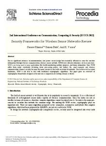
pairing. Although the current Bluetooth version is 4.2, Bluetooth continues to use SSP to support the current Bluetooth version is 4.2, Bluetooth continues to use SSP to support compatibility with compatibility with previous versions [9]. previous versions [9]. As shown in Figure 1 and Table 1, SSP consists of five phases. Phase 1 uses the Diffie-Hellman As shown in Figure 1 and Table 1, SSP consists of five phases. Phase 1 uses the Diffie-Hellman (DH) key exchange. However, DH key exchange has vulnerabilities to man-in-the-middle (MITM) (DH) key exchange. However, DH key exchange has vulnerabilities to man-in-the-middle (MITM) attacks [10]. attacks [10].
Figure Figure1. 1. Simple Simple secure secure pairing pairing with withaanumeric numericcomparison comparisonassociation associationmodel model[9]. [9].
Toresolve resolve MITM attack problem, SSP an adopts an association model: either numeric To thethe MITM attack problem, SSP adopts association model: either numeric comparison, comparison, passkey entry, Just Works, or out of band (OOB). One of these association models passkey entry, Just Works, or out of band (OOB). One of these association models adopted in Phase 2 adopted in Phase 2 differs based on the I/O capability of the electronic devices that connect to one
Sensors 2017, 17, 752
3 of 17
differs based on the I/O capability of the electronic devices that connect to one another. The I/O capability of the devices to be connected is exchanged before Phase 1 of SSP. The devices then choose a single association model in Phase 2. Phases 3 and 4 check and combine both types of information. Phase 4 then creates a link key used for authentication. An encryption key is created and encryption is conducted in Phase 5. However, this study does not describe the detailed process that follows Phase 2 because the proposed model employs a strain of passkey entry and numeric comparison in Phase 2. Table 2 describes the association models based on the I/O capability of the connected devices. DisplayOnly refers to those devices having only a display. DisplayYesNo is for those devices having a display and input channel for inputting “Yes” or “No.” KeyboardOnly refers to those devices having only a keyboard. NoInputNoOutput is for those devices having no I/O capability. KeyboardDisplay refers to those devices having both a display and keyboard. Table 1. Term of simple secure pairing with numeric comparison from Figure 1. Expression
Description
PKx
Public key of device x
PKxx
x-coordinate of PKx
SKx
Secret (private) key of device x
DHKey
Diffie-Hellman key
Nx
Nonce (unique random value) from device x
rx
Random number generated by device x
Cx
Commitment value from device x
f1()
Used to generate the 128-bit commitment values Ca and Cb (ex. f1(PKbx,PKax,Nb,0) = HMAC − SH A − 256 Nb ( PKb PKa 08 )mod2128 )
f2()
Used to compute the link key (ex. f2(PKax,PKbx,Na,Nb) = SH A − 256( PKax PKbx Na Nb)mod232 )
f3()
Used to compute the check values Ea and Eb in Authentication Stage 2 (ex. f3(DHkey,Na,Nb,rb,IOcapA,A,B) = HMAC − SH A − 256DHkey ( Na Nb rb IOcapA A B) )
g()
Used to compute numeric check values
IOcapx
IO capabilities of device x
x
Bluetooth device address of device x
Ex
Check value from device x
LK
Link key
Vx
Confirmation value on device x
Table 2. Association model based on I/O capability [9]. Initiator
Responder
Association Model
DisplayOnly
KeyboardOnly KeyboardDisplay
Passkey Entry
DisplayYesNo KeyboardDisplay
Numeric Comparison
KeyboardOnly
Passkey Entry
Any equipment except NoInputNoOutput
Passkey Entry
DisplayOnly KeyboardOnly
Passkey Entry
DisplayYesNo KeyboardDisplay
Numeric Comparison
DisplayYesNo
KeyboardOnly
KeyboardDisplay
Sensors 2017, 17, 752
4 of 17
OOB is known to be resistant to MITM attacks. However, the electronic devices must support other communication methods or channels in order to apply OOB. In numeric comparison, the devices display a number and users confirm whether the number displayed corresponds to the device to be connected in the pairing process [9]. The association model for numeric comparison can prevent MITM attacks. However, a display and confirmation process is required for every connection. Moreover, if the same passkey is used, this association model cannot prevent MITM attacks [11]. Furthermore, if the devices do not have displays, numeric comparison cannot be applied [9]. However, the proposed model does not require display equipment. During the passkey entry process, a given user inputs the passkey into a device and the devices to be paired compare both passkeys [9]. For the passkey entry, each connection requires user input. If the same passkey is used for every connection, this association model cannot prevent MITM attacks [11]. Just Works is nearly identical to numeric comparison. However, Just Works does not display a number. Therefore, the devices to be connected omit the comparison process conducted by users and proceed to the subsequent step. Without displaying a number, the devices cannot be alerted to MITM attacks [12–15]. In this study, an enhanced SSP that uses signal intervals is proposed to improve SSP security and user convenience. Specifically, the proposed scheme improves Phase 2 of SSP with numeric comparison. This SSP includes the challenge-respond method [9]. When a random number or nonce is transferred, the signal interval that expresses the nonce is delivered. Using a pre-defined function and the nonce transferred previously, the matching rule based on the quantization level between the signal interval and nonce is renewed. Specifically, the matching rule defines the quantization level with which the signal intervals match nonces. Due to delay, error, or other interference from physical signals, it is difficult for the intended signal interval to be delivered precisely. To reduce the error sensitivity of the physical signals, this study introduces the quantization level of the signal interval instead of using the analog characteristics of the physical signal [16]. Since the quantization level is renewed, the device that knows the previous nonce can determine the next new signal interval. During the initial step, the devices to be initially connected do not have any previous shared nonces. Therefore, users must input a 64-bit passkey. However, this input is required only once, that is, when the two devices are connected for the first time. Since the passkey entered by the user is not transferred as data, should a third party eavesdrop on the signals, it cannot determine the passkey information. Therefore, the proposed model can also be applied in the case of a fixed PIN. This fixed PIN is saved in the device that does not have any input method/input device. Since the devices can adopt the fixed PIN, this association model can be applied to a case in which one of two devices does not have input capability if they have the same fixed PIN. Regular users of Bluetooth generally use Bluetooth communication to connect laptops, desktops, or smartphones to speakers, headsets, or earphones. As indicated in Table 2, current devices use Just Works because laptops, desktops, and smartphones employ displays and keyboards. On the other hand, speakers, headsets, and earphones are NoInputNoOutput. However, if the proposed model is adopted, the devices can connect with each other using a fixed PIN. Moreover, more than two devices attempting to pair can recognize each other and prevent MITM attacks. In addition, the devices do not need to support other communication methods or channels. The proposed method has an advantage in that third parties attempting to disguise themselves cannot determine the nonce shared between the devices to be connected. This is because they cannot calculate the quantization level renewed at every connection. Unlike current SSPs, the proposed method can minimize user interference. Since the passkey entered by a user is not transferred as data, if a third party eavesdrops on the signals, it cannot determine the passkey information. Additionally, since information to be transferred is expressed by the time interval of the physical signals, the attacker that cannot determine the quantization level cannot determine the meaning of the signal intervals. Due to
Sensors 2017, 17, 752
5 of 17
the threat of leaking the quantization level when a fixed quantization level is used, the transferred number is used to renew the existing quantization level. Therefore, MITM attacks can be prevented. This study considers related works in Section 2. Section 3 describes the proposed scheme of the new association model. Section 4 describes the results of experiments conducted in various environments and analyzes the security of the proposed Scheme. Security of proposed model is analyzed in Section 5. Section 6 summarizes and concludes the study. 2. Related Works Electronic devices exchange certain information in order to authenticate one another or create a key. In anonymous communication, devices basically exchange a given value and then authenticate each other. In ZigBee, authentication is performed using the devices’ pre-shared master key, ID, and nonce. By compounding the master key, ID, and nonce, a link key is created [17]. The master key is either transferred or pre-installed. In wireless LAN, access control that uses a service set identifier (SSID), address authentication through media access control (MAC), shared key authentication, or the IEEE802.1x method, is used [18–21]. These methods are also implemented during communication among devices. However, because such communication is vulnerable to sniffing, some countermeasures are required [3]. For example, transferring the master key through communication is vulnerable to replay attacks [22]. Therefore, many studies have been conducted on key distribution [23,24] to resolve these kinds of threats. Since Bluetooth has the same vulnerabilities, SSP is adopted. However, SSP is not secure. Therefore, many methods have been proposed to supplement or replace SSP [25–27]. One method exists in which information is stored using the device ID in a database [25]. This method uses a pre-shared password and extracts a key from the password. The key encrypted by a public key is then delivered. However, this database must be pre-shared. Moreover, if the ID of the new connecting device does not exist in the database, the device cannot connect. This is another case of giving and receiving information through communication. Therefore, the sniffing threat remains. If the inner algorithm is revealed through sniffing, this method is not secure. Another proposal assumes a situation in which many master devices are present in a piconet, and two given devices among the master devices create a key [26]. The key is then delivered to other devices by means of multicast and used for authentication. However, this method cannot be used for two-device communication and cannot check for an attacker attempting to infiltrate the piconet. In addition, distinguishing a node or device is possible by using the analog character of the signals generated by the node [28]. SSP is processed using this character [27]. However, this method employs an OOB channel to prevent MITM attacks. Therefore, a device that does not support this type of channel for other communication cannot employ this method. Moreover, the recognition rate is only 70%. Thus, identical devices that attempt to authenticate each other may fail authentication at a rate of 30% [28]. In addition, this method requires an additional server to verify authentication results. By contrast, the proposed method does not require a piconet or an additional server. In addition, the accuracy of our method was approximately 95% in our experiment. Another suggested use of quantization is for an electronic device to project data onto the space containing a random array. This would be performed after the device extracts biological data. This model then applies dynamic thresholding and encrypts the data before transferring them [29]. Furthermore, another proposed error recovery method exists that outperforms the existing dithered quantization method because it uses random quantization of the source signal [29,30]. 3. Enhanced SSP Using Signal Intervals The scheme proposed shows that the time interval between consecutive physical signals can also be used to improve SSP. As indicated in [11], passkey entry has security flaws. Therefore, this study proposes an enhanced SSP using signal intervals. This SSP is based on numeric comparison and passkey entry for pairing devices that possess no display window. In addition, the proposed
Sensors 2017, 17, 752 Sensors 2017, 17, 752
6 of 17 6 of 16
counterpart must have its input subpart to acquire the passkey. Therefore, the other method doesdevice not require an input passkey whendevice the passkey is saved to the devices. In this case, pairing device does notmust require input subpart device, such as keyboardTherefore, [12–15]; the the counterpart device haveitsitsown input subpart device to acquire thea passkey. thelegacy other passkeydevice entry requires inputits passkey at each pairing. By contrast, proposed scheme does not pairing does not an require own input subpart device, such as athe keyboard [12–15]; the legacy require an input passkey exceptpasskey at the at initial the the initial connection, thedoes current passkey entry requires an input eachconnection. pairing. By After contrast, proposed scheme not nonce isanused instead of except the passkey. require input passkey at the initial connection. After the initial connection, the current nonce is used instead of the passkey. 3.1. Assumption 3.1. Assumption It is assumed that the received signal strength indication (RSSI) of the signals is higher than −70 assumed that loss. the received signal strength indication (RSSI) of the signals is higher than dbmIttoisprevent packet −70 dbm to prevent packet loss. can falsify device addresses, each device uses its resolvable private In addition, because attackers In addition, because [9], attackers falsify device addresses, device uses resolvable random device address whichcan is composed of 48 bits that,each themselves, are its composed ofprivate 24 bits random device address [9], which composed of 48value. bits that, are composed 24 bits each each of random value and a hashisof the random Thethemselves, devices require a local orofpeer identity of randomkey value and to a hash ofthe thehash random value. The devices require a local or peer identity resolving resolving (IRK) create value. To share IRK, the devices should connect at least once. key to create the hash value. To share IRK, the devices at least IRKprocess is shared IRK(IRK) is shared during the first pairing. Specifically, IRK isshould sharedconnect following the once. pairing to during first sniffing. pairing. Specifically, IRK following pairing process to protect from protect the it from In Section 3.6, it is is shared assumed that thethe devices have already shared it IRK. A sniffing. In private Sectionrandom 3.6, it is device assumed that the have already shared IRK. private resolvable address candevices support device identification by A theresolvable hash value, even random device identification by the hash value, even when the device when thedevice deviceaddress addresscan hassupport changed. address has changed. In addition, the pairing devices share necessary information such as I/O capability and Bluetooth In addition, the pairing devices share necessary information such asThis I/O study capability and Bluetooth address. The proposed scheme must share additional information. proposes that the address. Thebe proposed scheme share additional information. This study proposes that the information shared during themust paging process. information shared during the process. Finally,be RTC is necessary to paging obtain date information. The date information is used to calculate Finally, RTClevel. is necessary to obtain datedevices information. The date information is used to acalculate the quantization The RTCs of the two to be paired can be synchronized using method the quantization Thepaging RTCs of the twoIPdevices be paired can synchronized using a method proposed by [31]level. during process; or GPStocan be used tobe synchronization of RTCs. If the proposed by [31] during paging process; IP or GPS beof used to synchronization RTCs. If the devices devices fail to synchronization, the mixture ofcan IRK two devices can be of used instead of date fail to synchronization, the mixture of IRK of two devices can be used instead of date information. information. 3.2. 3.2. Random Random Number Number Sharing Sharing Figure the the nonce sharing process that uses theuses time interval consecutive Figure2 2illustrates illustrates nonce sharing process that the timebetween intervaltwo between two signals. The signals. information delivered bydelivered the two by signals is the maximum signal interval consecutive The information the two signals is the maximum signalbetween interval consecutive signals. These setsThese of datasets should be as short be as possible to save energy. Device B calculates between consecutive signals. of data should as short as possible to save energy. Device the values necessary to process SSP with the transmitted nonce. B calculates the values necessary to process SSP with the transmitted nonce.
Figure Figure 2. 2. Random Random number number selection selection using using signal signal interval. interval.
Figure 33 shows shows the the enhanced enhanced version version of Phase 2 of the SSP. SSP. The The reason reason both both parties parties must must check check Figure Ca and and Cb Cb is is to to create create aa pre-existing pre-existing nonce nonce for for both both devices. devices. Both ra and rb are set to to 00 in in order order to to Ca adopt the the legacy legacy scheme scheme of of numeric numeric comparison. comparison. Ca Ca and and Cb Cb are are used used to to check check ra and rb are are properly properly adopt transmitted. In In addition, addition, Va Vaand andVb Vbare areexchanged exchangedto toidentify identifyeach eachother. other. transmitted. Due totocommunication communication delay, signal an abnormal the intended time Due delay, signal loss,loss, or anorabnormal devicedevice status, status, the intended time interval interval might not be transferred. Therefore, quantization is used to reduce error sensitivity caused might not be transferred. Therefore, quantization is used to reduce error sensitivity caused by physical by physical environments. Therefore, can obtainlike tolerance, like the conversion process of environments. Therefore, this schemethis can scheme obtain tolerance, the conversion process of an analog an analog a digital signal. signal to a signal digitalto signal.
Sensors 2017, 17, 752
7 of 17
Sensors 2017, 17, 752
7 of 16
Sensors 2017, 17, 752
Device A
Device B
Device A Select random Na random SetSelect ra and rb to 0Na
7 of 16
Device B Select random Nb
Phase 2 Phase 2
Select random Set ra and rb toNb 0
Set ra and rb to 0 0) Ca = f1(PKax, Pkbx, Na,
ra andPkax, rb to 0Nb, 0) Cb = Set f1(PKbx,
Ca = f1(PKax, Pkbx, Na, 0) Cb = f1(PKbx, Pkax, Nb, 0) If no previous nonce Na’ or Nb’, If no have previous nonce Na’ or Nb’, obtain a passkey from user and obtain a passkey from user and If no previous nonce Na’ or Nb’, If no have previous nonce Na’ or Nb’, calculate time interval calculate time interval obtain a passkey from user and obtain a passkey from user and calculate time interval calculate time interval Cb, Max of this time interval Cb, Max of this time interval (Empty)
This time interval represents Nb This time interval
This time interval represents Na This time interval
Ca, Max of(Empty) this time interval
represents Na
Ca, Max of this time interval (Empty)
represents Nb
(Empty) Check whether Cb = f1(PKbx, Pkax, Nb, 0) Check whether Ca = f1(PKax, Pkbx, Na, 0) If check abort Pkax, Nb, 0) If check abortPkbx, Na, 0) Check whether Cbfails, = f1(PKbx, Check whether Ca =fails, f1(PKax, If check fails, abort If check fails, abort Va = g(Pkax, PKbx, Na, Nb) Va = g(Pkax, PKbx, Na, Nb) Va = g(Pkax, PKbx, Na, Nb) Va = g(Pkax, PKbx, Na, Nb) Each device checks whether Va=Vb If check fails,whether abort Va=Vb Each device checks If check fails, abort Na and Nb are saved to be used as previous nonce at both A and B. If subsequent connection Na A and NbBare saved to by be used asA, previous nonce atnonce; both A otherwise, and B. If subsequent between and is initiated device Na is previous if initiatedconnection by device B, between A and B is initiated by device is previous nonce; otherwise, if initiated by device B, NbA,is Na previous nonce. Nb is previous nonce.
Figure Figure 3. 3. SSP SSPPhase Phase22that thatadopts adoptsthe theproposed proposedscheme. scheme. Figure 3. SSP Phase 2 that adopts the proposed scheme.
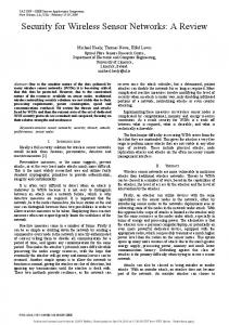
Figure 4 is a block diagram showing the chip that calculates the quantization level and the signal Figure 4 is4aisblock diagram showing quantizationlevel leveland andthe thesignal signal Figure a block diagram showingthe thechip chipthat thatcalculates calculates the the quantization interval that generates the signals. The date information shows the time in ms units after 1 January interval thatthat generates the the signals. TheThe datedate information shows thethe time in ms units after 1 January 1970. interval generates signals. information shows time in ms units after 1 January 1970. The connected device information shows the Bluetooth device address. The previously-saved The1970. connected device information shows the Bluetooth device address. The previously-saved nonce is The connected device information shows the Bluetooth device address. The previously-saved nonce is searched for using this address. If no nonce was previously saved, the user must input the searched using this no nonce previously saved, the userthe must input passkey. nonce for is searched for address. using thisIfaddress. If was no nonce was previously saved, user mustthe input the passkey. The quantization level is calculated using the pre-existing nonce or passkey input, as well The quantization level is calculated the pre-existing nonce or passkey as as well Thepasskey. quantization level is calculated using theusing pre-existing nonce or passkey input, input, as well the as the date information, which are all shared by the two devices. Since the signal interval is calculated the date information, which are all shared thedevices. two devices. signal interval is calculatedby dateasinformation, which are all shared by theby two SinceSince the the signal interval is calculated by multiplying the quantization level and random number, the signal receiver can determine the by multiplying the quantization level and random number, the receiver signal receiver can determine the multiplying the quantization level and random number, the signal can determine the sender’s sender’s random number by dividing the signal interval by the quantization level. sender’s random number by dividing the signal interval by the quantization level. random number by dividing the signal interval by the quantization level.
Date Date information information Connected Connected Device Device information information
Quantization level Quantization level calculator calculator
Time Timeinterval interval calculator calculator
Connected device Connected device information manager information manager && storage storage
Random Randomnumber number generation generation
Signal Signal Interval Interval
Figure 4. of the device paired that generates Figure 4. Architecture the device paired that generatesthe thesignals signalsrepresenting representing random numbers. Figure 4. Architecture Architecture of of the device paired that generates the signals representingrandom randomnumbers. numbers.
Sensors 2017, 17, 752 Sensors 2017, 17, 752
8 of 17 8 of 16
3.3.Quantization QuantizationLevel LevelManagement Management 3.3. 3.3.1. 3.3.1.Quantization QuantizationLevel LevelInitialization Initialization Information Informationfor fordevices devicespreviously previouslyconnected connectedand andthe thepre-existing pre-existingnonce nonceused usedare aresaved savedand and managed managedasasshown shownininFigure Figure4.4.During Duringthe theinitial initialconnection, connection,because becausethe theused usedstorage storagedoes doesnot not contain any information about the devices to be connected, the user must input a 64-bit passkey. contain any information about the devices to be connected, the user must input a 64-bit passkey. Otherwise, Otherwise,a afixed fixedpasskey passkeycan canbebeused usedbased basedon onthe thedevices’ devices’I/O I/Ocapabilities. capabilities.Since Sinceaapasskey passkeyisisused, used, the thequantization quantizationlevel levelisisdifferent differentatateach eachpairing. pairing.However, However,pairing pairingdevices devicescan canachieve achievethe thesame same quantization quantizationlevel levelififthe thesame samepasskey passkeyisisinput. input.This Thisinput inputisisrequired requiredwhenever whenevernew newdevices devicesattempt attempt totoconnect. connect.However, However,once oncethe thepasskey passkeyhas hasbeen beenentered enteredfor forthe thedevice devicepair, pair,subsequent subsequentconnections connections between betweenthe thedevice devicepair pairdo donot notrequire requirea anew newpasskey passkeyfor foreach eachconnection. connection. The iscalculated calculatedatatthe the subsequent circuit as shown in Figure 5. Incircuit, this Thequantization quantization level is subsequent circuit as shown in Figure 5. In this circuit, theinformation date information is inunits ms units 1 January 1970. example, thedate dateinformation informationis the date is in ms afterafter 1 January 1970. ForFor example, if if the is1445242302710 1445242302710and andthe thepasskey passkeyisis 0,0, the the value value is is 1445242302710 1445242302710 after the OR OR gate gate isis passed. passed. Subsequently, is extracted extractedfrom fromthe thelower lowereight eight bits after passing XOR Subsequently,aa value value of of 129 is bits after passing thethe XOR gate.gate. The The minimum quantization level is 625 µsBluetooth in Bluetooth Therefore, the result of quantization the quantization minimum quantization level is 625 µ s in [9]. [9]. Therefore, the result of the level level is 80.625 After the quantization is calculated, as shown in Figure 5, the devices multiply is 80.625 ms. ms. After the quantization levellevel is calculated, as shown in Figure 5, the devices multiply the the nonce provided therandom randomnumber numbergenerator generatorby by the the quantization quantization level. In nonce provided byby the In this this example, example,ififthe the time timeinterval intervalunit unitisisms, ms,aasmall smallnonce noncecan canresult resultininaalarge largetime timeinterval. interval.However, However,ififthe thequantization quantization level levelunit unitisisµs, μs,the thetime timeinterval intervalcan canbe bereduced. reduced.When Whenthe thetime timeinterval intervalisisdelivered deliveredto tothe thereceiver, receiver, the thenonce noncerepresents representsthe thequotient quotientofofthe thedivision divisionofofthe thetime timeinterval intervalbybythe thequantization quantizationlevel. level. Since SinceBluetooth Bluetoothcan cansynchronize synchronizetime timewith withcircumjacent circumjacentdevices devices[9], [9],the thedevices devicescan canuse usethe thesame same time. time.IfIfaaconnection connectionisissuccessful, successful,information informationon onthe theconnecting connectingdevice deviceand andrandom randomnumber numberused usedisis saved savedtotocreate createthe thenext nextnew newquantization quantizationlevel. level. Date information [63:0]
[63:48]
Previous nonce [63:0]
[31:16]
Minimum Quantization Level [9:0]
[15:0]
[7:0] [47:32]
Multiplyer
Quantization Level [17:0]
Figure5.5.Example Exampleofofquantization quantizationlevel levelcalculator. calculator. Figure
Figure 5 provides an example of a quantization level calculator that conducts the renewal Figure 5 provides an example of a quantization level calculator that conducts the renewal process. The quantization level calculator can be modified based on the practical specifications of the process. The quantization level calculator can be modified based on the practical specifications of the real devices. real devices. 3.3.2. Quantization Level Renewal 3.3.2. Quantization Level Renewal If no renewal occurs, an adversary can obtain information about a quantization level when many If no renewal occurs, an adversary can obtain information about a quantization level when many pairing cases are observed. Therefore, the quantization level must be renewed. pairing cases are observed. Therefore, the quantization level must be renewed. When devices to be connected have, in fact, already connected (at an earlier time), the data When devices to be connected have, in fact, already connected (at an earlier time), the data recorded from that earlier connection exists in storage, as indicated in Figure 4. Figure 4 shows the recorded from that earlier connection exists in storage, as indicated in Figure 4. Figure 4 shows the architecture of the device to be paired in order to renew the quantization level. The new quantization architecture of the device to be paired in order to renew the quantization level. The new quantization level is calculated using the previous connection information. Two random variables exist. The level is calculated using the previous connection information. Two random variables exist. The previous previous nonce is a random number created by the device that initiates the connection. In Figure 3, the random numbers are Na and Nb. The previous nonce is Na if the subsequent connection is
Sensors 2017, 17, 752
9 of 17
nonce is a random number created by the device that initiates the connection. In Figure 3, the random numbers are Na and Nb. The previous nonce is Na if the subsequent connection is initiated by device A. Since the saved nonce is the same for the devices to be connected, each device can calculate the same result using this shared nonce. Figure 6 shows the algorithm for the renewal process. Through this algorithm, the devices can avoid leaking the renewed quantization level whenever the devices establish new connections. When a new is established, the nonce changes. Therefore, the quantization level is renewed Sensors 2017, 17,connection 752 9 of 16 whenever a new connection is established. The same signal intervals can represent different numbers initiated by device A. Since the saved nonce the is the same can for the devices be connected, as the quantization level changes. Therefore, devices protect theirtodata because theeach thirddevice party can calculate the same result using this shared nonce. cannot determine the real value shared. Set Initial Quantization level
Do you want to choose a random number to be shared? Yes Measure the time interval between two consecutive signals Extract the transmitted number using the quantization levels No
Was the same random number chosen successfully? Yes Renew the quantization level by the transmitted number
Figure Figure 6. 6. Quantization-level Quantization-level renewal renewal process. process.
Figure 6 shows the algorithm for the renewal process. Through this algorithm, the devices can 3.4. Countermeasures for Packet Loss avoid leaking the renewed quantization level whenever the devices establish new connections. When The loss rate iniswireless communication is greaterTherefore, than that inthe wired communication. a new connection established, the nonce changes. quantization level is renewed As explained in Section is 3.3.1, when devices acquire 80.625 ms of quantization if thenumbers random whenever a new connection established. The same signal intervals can representlevel, different number generator changes the nonce to 8, the signal interval becomes 645 ms. However, one two as the quantization level changes. Therefore, the devices can protect their data because the thirdofparty consecutive signals can bevalue lost. To solve this problem, this study proposes that every signal have its cannot determine the real shared. data express the maximum signal interval as shown in Figure 3. The receiver waits for the next signal 3.4. Countermeasures Packet Loss If the maximum signal interval expires, the receiver will conclude during the maximumfor signal interval. that the second signal is lost, and require a new signal interval. If an empty signal is delivered first, The loss rate in wireless communication is greater than that in wired communication. the receiver will know that the first signal is lost. The maximum signal interval is calculated using As explained in Section 3.3.1, when devices acquire 80.625 ms of quantization level, if the Equation (1): random number generator changes the nonce to 8, the signal interval becomes 645 ms. However, one M = (1 + X) P (1) of two consecutive signals can be lost. To solve this problem, this study proposes that every signal have itsMdata themaximum maximumand signal interval as shown in Figure 3. The receiver waits the where andexpress P are the intended signal intervals, respectively. X should be afor value next signal during the maximum If signal the maximum signal interval the receiver between 0 and 1. However, if X issignal very interval. small, the can be ignored when aexpires, slight delay occurs. will concludeifthat and a newdelay signalisinterval. If an empty is For example, P isthe 645second ms andsignal X is 0,isMlost, is 645 ms.require If the signal 1 ms, a 646-ms signalsignal interval delivered first, theHowever, receiver will that thebefirst signalInisthis lost.case, Thethe maximum interval is would be sensed. this know value would invalid. receiver signal requires that the calculated using Equation (1): sender retransmit two consecutive signals. In addition, if X is a large value, the receiver must wait for the lost packet during the surplus time. Therefore, it is proper for X = 0.5, academically speaking. M = (1 + X) P (1) Nonetheless, the value of X can be adjusted to reduce the error rate caused by the poor status of where M andcommunication. P are the maximum and intended signal respectively. X should be aon value the physical The transmitter sets X to intervals, 0.5 initially and can adjust X based the between 0 and 1. However, if X is very small, the signal can be ignored when a slight delay occurs. authentication success rate. For example, if P is 645 ms and X is 0, M is 645 ms. If the signal delay is 1 ms, a 646-ms signal interval would be sensed. However, this value would be invalid. In this case, the receiver requires that the sender retransmit two consecutive signals. In addition, if X is a large value, the receiver must wait for the lost packet during the surplus time. Therefore, it is proper for X = 0.5, academically speaking. Nonetheless, the value of X can be adjusted to reduce the error rate caused by the poor status of the physical communication. The transmitter sets X to 0.5 initially and can adjust X based on the authentication success rate.
Sensors 2017, 17, 752
10 of 17
3.5. Transmitted Value Management Since attackers can mimic the authentication of normal devices or attempt to use brute force during attacks using clues from the maximum signal interval, when a counterpart transmits the wrong Sensors 2017, 17, 752 authentication value, the devices stops the pairing process, as in the current association model.10 of 16 3.6. Counterfeit Detection With interval. Thus, if With the the proposed proposedmodel, model,the thenonce noncecan canbe berecognized recognizedbybyestimating estimatingthe thesignal signal interval. Thus, any attacker watches if any attacker watchesthe thesignals signalsand andcopies copiesthem, them,the theaccurate accuratevalue value cannot cannot be be transferred transferred to the receiver because the signal interval between two consecutive signals is different from the intended interval. interval. In other words, the receiver cannot be authenticated. To prevent this situation, when a device perceives perceives an an imitated imitated signal, signal, the the device device creates creates aa new device address. address. If old and new device addresses from identical devices exist, the receiver receiver ignores ignores the the old old device device addresses. addresses. 4. Evaluation 4. Evaluation To To analyze analyze the the security security of of the the proposed proposed scheme, scheme, the the attack attack scenario scenario suggested suggested by by [11], [11], in in which which the passkey entry is violated, is used here. This is because the proposed method in this study the passkey entry is violated, is used here. This is because the proposed method in this study uses uses passkey passkey entry entry and and numeric numeric comparison comparison to to improve improve the the security security of of the the current current passkey passkeyentry. entry. The repeated using a bit number of The passkey passkey entry entrymethod methodisisillustrated illustratedininFigure Figure7.7.The Theprocess processis is repeated using a bit number the passkey. Note that ra and rb in each round are the values of the bits of the passkey. The passkey of the passkey. Note that ra and rb in each round are the values of the bits of the passkey. The passkey entry entry uses uses ra, ra, rb, rb, Na, Na, and and Nb Nb of of the the last last round round in in Phase Phase 33 as as well. well.
Device A
Device B
User
Inject secret ra Set ra = rb
Inject secret rb Set rb = ra
Select random Na
Select random Nb
Ca = f1(PKax, Pkbx, Na, ra)
Cbi = f1(PKbx, Pkax, Nb, rb) Ca Cb Na Check if Ca = f1(PKax, Pkbx, Na, rb) If check fails, abort Nb
Check if Cb = f1(PKbx, Pkax, Nb, ra) If check fails, abort
Figure 7. 7. Passkey entry [9]. [9]. Figure Passkey entry
The point of these attack scenarios is to implement to identify an MITM in Phase 1 and determine the last bit of the passkey. All information used after Phase 1 can be monitored because it is transmitted in plain text. The last bit of the passkey is then used for ra and rb. In this case, ra and rb are identical because the passkeys of the pairing devices are the same. The attacker can easily determine rx by calculating Cx and then comparing the calculated and transmitted values using legitimate pairing devices because the last bit is 0 or 1. Moreover, the legacy SSP has a security flaw a fixed passkey is used. This is because ra and rb
Sensors 2017, 17, 752
11 of 17
The point of these attack scenarios is to implement to identify an MITM in Phase 1 and determine the last bit of the passkey. All information used after Phase 1 can be monitored because it is transmitted in plain text. The last bit of the passkey is then used for ra and rb. In this case, ra and rb are identical because the passkeys of the pairing devices are the same. The attacker can easily determine rx by calculating Cx and then comparing the calculated and transmitted values using legitimate pairing devices because the last bit is 0 or 1. Moreover, the legacy SSP has a security flaw a fixed passkey is used. This is because ra and rb are always the same in all pairing processes (they are either 0 or 1). In addition, Nx is transmitted in plain text. Therefore, an adversary can obtain all information during the SSP process. By contrast, an adversary cannot determine Na and Nb easily using the time interval of our scheme because this interval is already included in the nonce (Nx) and uses all bits of the passkey. This proposed method does not directly reveal both the passkey and nonce. Therefore, the proposed scheme can be applied when a pairing device has a fixed passkey. A fixed passkey is not renewed. However, after the first pairing, the pre-existing nonce is used instead of date information. Therefore, an adversary cannot assume or detect the quantization level and thus extract the nonce from the current time interval. In addition, Table 3 shows the comparison of existing protocols with our approach. The proposed method does not need any extra device, but shows high accuracy. Table 3. Comparison of existing protocols with our approach.
MITM
Existing SSP [9]
Diallo [25]
Biswas [26]
Pasanen [27]
Our Study
4 (All scheme except numeric comparison)
4 (Connection of new device)
4 (Infiltrating attacker in the piconet)
X
X
Number of devices
2
3
At least 3
2
2
Accuracy
Not mentioned
Not mentioned
Not mentioned
About 70%
About 95%
O: Possible, 4: Partially Possible, X: Impossible, (): Possible Case or Method.
5. Experiments 5.1. Accuracy Test Settings An experiment was conducted in which a nonce used to create a key or to authenticate devices is represented by a signal interval between two consecutive signals of Bluetooth low energy (BLE). BLE was used because Bluetooth classic has its time slot of 625 µs and the advertisement function of BLE has the signal interval that is a time slot of 625 µs in the range from 20 ms to 10.24 s. Some delay is added to the signal interval [9]. The delay of BLE can be negated by adjusting the quantization level. The checkpoint is the location to which an intended value is transferred. It is assumed that the initial quantization level had been determined in advance and that other information used to authenticate each device had been exchanged, with the exception of the nonce. After nonce transmission, a device does not respond to the other device and simply displays that value. In addition, this test ignores the manner in which authentication fails, i.e., the renewal of the quantization level through the authentication value, and saving or deleting the transferred value. Bluetooth beacon signals were used in this experiment. A desktop equipped with a Bluetooth dongle and using Ubuntu OS transmitted the beacon signals to a laptop equipped with the same Bluetooth dongle and Ubuntu OS. Specifications for the desktop PC were as follows: Intel core i7-4790 CPU and 8 GB RAM. The laptop had an Intel core i5-3230M CPU and 4 GB RAM. The transmitted nonce was compared with the number calculated by the laptop by estimating the signal interval between two consecutive signals. The Bluetooth dongle was a ZIO BT40 of Bluetooth CSR 4.0 made by ZIO company in goyang of Korea, which supports Bluetooth 4.0. The distance between two devices was 50 cm. The intended signal intervals were 62.5 ms, 313 ms, and 625 ms. The valid value was assumed to be between the intended time intervals of −10 ms and +10 ms.
Sensors 2017, 17, 752
12 of 17
Each signal contained information that the maximum signal interval was 100 ms, 500 ms, and 1 s. For the beacon, the feedback for packet loss was set so that it need not be considered. In addition, the device was set so that it waited for subsequent signals that were repeatedly transmitted. If the device was not a beacon, the feedback might not have been required when packet loss occurred. Through such feedback, the transmitter could generate new signals. The given signal intervals represent values such as 100, 500, 1000. 5.2. Quantization Level Management 5.2.1. Effect of Maximum Signal Interval Before conducting an actual experiment, a test was performed to determine the influence of the maximum signal interval. The distance between two devices was 50 cm. In addition, 62.5 ms of the time interval represents a value of 100. The signal interval was ignored if it exceeded the maximum, and was measured again. In this situation, the average signal intervals, standard deviation, and accuracy were estimated. Table 4 lists the results. By adapting the maximum signal interval, an improved outcome was obtained with higher accuracy and a time interval that was close to that intended in comparison to the outcomes obtained when not adapting it. Table 4. Effect of maximum signal interval. Classification
Time Interval (ms)
Accuracy (%)
Adapted Not adapted
67.15 ± 2.14 78.13 ± 28.2
98.67 81.58
Table 5 describes the accuracy of the transferred nonce through the time interval between signals. The results indicate an accuracy of approximately 95% to 98%. This result is considered in order to determine the quantization level. In addition, the time for the quantization level should be longer than the overhead of the estimated time interval in order to reduce the error rate. Table 5. Random number mapping. Random Number
Time Interval (ms)
Accuracy (%)
100 500 1000
67.16 ± 2.92 317.23 ± 3.32 629.81 ± 3.04
98.67 94.67 98.67
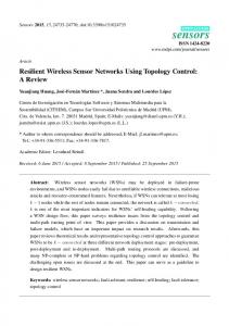
5.2.2. Signal Interval between Correct Values Based on Distance Figure 8 shows the time necessary to obtain an accurate nonce based on the distance between the devices that are to be connected. In other words, Figure 8 shows the time interval between accurate nonce acquisition and the next accurate nonce acquisition. The experiment showed how the proposed model was affected by signal loss, meaning that if the communication environment was bad, the scheme does not work effectively. No obstacle was present between the two devices. The time interval required to obtain accurate nonces increased rapidly at a distance longer than 10 m. In other words, the proposed model is effective within 10 m.
the devices that are to be connected. In other words, Figure 8 shows the time interval between accurate nonce acquisition and the next accurate nonce acquisition. The experiment showed how the proposed model was affected by signal loss, meaning that if the communication environment was bad, the scheme does not work effectively. No obstacle was present between the two devices. The time interval required to obtain accurate nonces increased rapidly at a distance longer than 10 m. In Sensors 2017, 17, 752 13 of 17 other words, the proposed model is effective within 10 m.
Figure 8. Random number sharing affected by signal loss. loss.
5.2.3. Interference Effect Effect Sensors 2017, 17, 752 of 16 Wireless communication show Wireless communication can can be be affected affected by by interference. interference. An experiment was conducted to13
the interference effect. The The number numberof ofdevices devicesaccessing accessingBLE BLEsignal signalininthe thesame samechannel channelwas wasset setasasa avariable. variable.The TheBLE BLEsignal signalinterval intervalwas waschosen chosenas as20 20ms, ms,which whichisisthe theminimum minimum BLE BLE signal signal interval interval [9], [9], to show show an an obvious obvious inference inference effect effect in in this this experiment experiment (except (exceptBLE BLEdelay). delay). to Figure 99 describes describes the the interference interference effect effect depending depending on Figure on the the number number of of devices devices sending sending signals. signals. This experiment was designed to show an environment of the proposed scheme in This experiment was designed to show an environment of the proposed scheme in aa busy busy channel. channel. The number devices sending or receiving a packet every 20 ms. The number of of devices devicesmeans meansthe thenumber numberofof devices sending or receiving a packet every 20 The ms. factor of the distance causes packet loss. Therefore, the accuracy would be similar in any distance The factor of the distance causes packet loss. Therefore, the accuracy would be similar in any distance when the the minimum minimum signal signal interval interval is is set. set. Conversely, the interference interference effect effect may may lead lead to to some some delay delay when Conversely, the and then then decrease decrease accuracy. accuracy. When five devices devices sending sending signals signals every every 20 20 ms ms were were on on different different and When all all five channels from the device transferring nonce, the result was similar to that shown in Table 4. channels from the device transferring nonce, the result was similar to that shown in Table 4.
Figure 9. 9. Random number sharing sharing affected affected by by interference interference effect. effect. Figure Random number
This experiment shows an extreme case because the BLE interval in this experiment was set to This experiment shows an extreme case because the BLE interval in this experiment was set the minimum. In an ordinary case, the beacon signal interval is set to be longer to reduce power to the minimum. In an ordinary case, the beacon signal interval is set to be longer to reduce power consumption. Further, when a channel is busy, the device can change the advertisement channel to consumption. Further, when a channel is busy, the device can change the advertisement channel to diminish the interference effect [9]. If all channels are busy, the quantization level can be greater for diminish the interference effect [9]. If all channels are busy, the quantization level can be greater for better performance. better performance. 5.2.4. Implementation Implementation of of Random Random Number Number Mapping Mapping 5.2.4. Many studies information meant to be through a secure route Many studies have haveobtained obtainedsensitive sensitive information meant toprocessed be processed through a secure within hardware chips [32–34]. To improve security, hardware implementation has often been route within hardware chips [32–34]. To improve security, hardware implementation has often been considered [35]. To this effect, we implemented a field-programmable gate array (FPGA), namely, the Spartan6 XC6LX from Xilinx, and analyzed it using ISE based on Figure 6. The date information contained the current time expressed by a 64-bit integer, and the quantization level result was expressed by 8-bit data. Table 6 lists the time required to obtain a result after the input of each signal. As indicated in
Sensors 2017, 17, 752
14 of 17
considered [35]. To this effect, we implemented a field-programmable gate array (FPGA), namely, the Spartan6 XC6LX from Xilinx, and analyzed it using ISE based on Figure 6. The date information contained the current time expressed by a 64-bit integer, and the quantization level result was expressed by 8-bit data. Table 6 lists the time required to obtain a result after the input of each signal. As indicated in Table 6, the devices could acquire high-speed processing if a digital circuit was produced to implement the proposed model. In this experiment, the device required a processing time of within 16 ns. Table 6. Process time of random number mapping. Input
Processing Time (ns)
Date information Previous nonce Minimum quantization level
12.202–15.675 12.713–15.601 10.882–12.714
5.3. Overhead Analysis In the proposed method, a busy waiting time occurs for receiving two signals. However, this waiting time is not long when considering the communication time of Bluetooth signals. The time intervals in the program used in our experiment were set to 62.5, 313, and 625 ms. However, the estimated values had about 4~5 ms of errors on average because of advertisement delay [9]. Thus, this error is reduced. To consider the storage space required, this study used the circuit shown in Figure 6. In this circuit, the nonce and Bluetooth device address size were set to 8 and 6 bytes, respectively. Therefore, the required storage was 14 bytes per device. This means that if the device saved information about 1000 devices to be connected, it required 1.4 Kbytes. If the devices used 16 bytes of nonce, the devices required 22 bytes per device. 6. Conclusions This study proposed an improved SSP to transfer nonces through signal intervals between two consecutive signals. A non-encrypted nonce was transferred because the devices had not already created a key in SSP. Therefore, attackers could eavesdrop on, and collect information related to, key creation. In this association model, even if attackers eavesdropped on the signals, because they could not determine the quantization level, they were unable to determine what was being transferred. Furthermore, we showed that the proposed model does not require exchanging passkeys as data and that devices are secure when using a fixed PIN. The devices to be connected obtained the shared passkey that was inputted initially by the user or that was fixed in order to calculate the quantization level. Subsequently, the new quantization level was calculated automatically whenever the same devices attempted to connect with each other. In addition, we showed that applying the proposed scheme to other WSN is possible when the protocol includes a nonce transmission process. In other words, the nonce can be delivered using a time interval. Although numeric comparison and passkey entry require user confirmation whenever devices connect, we showed that the proposed model does not require additional user interference, except in the initial device connection. In WPAN, the pairing devices are constant. Therefore, the proposed association model can provide convenience and is effective for users. In addition, we suggested a hardware implementation to prevent software hacking. However, measuring the interval between two consecutive signals may be occasionally incorrect in multitasking environments. Moreover, this method is inefficient in high packet loss rate environments.
Sensors 2017, 17, 752
15 of 17
Therefore, applying the proposed random number sharing to near-field communication of IoTs would be effective. The target IoT devices to be connected should possess low specifications that cannot or do not require multitasking or overload applications. Acknowledgments: This work was supported by the ICT R&D program of MSIP/IITP (B0101-15-0266, Development of High Performance Visual BigData Discovery Platform for Large-Scale Realtime Data Analysis), and the MSIP (Ministry of Science, ICT and Future Planning) under the ITRC (Information Technology Research Center) support program (IITP-2016-H8501-16-1013) supervised by the IITP (Institute for Information & communication Technology Promotion), South Korea. Author Contributions: J.M., I.Y.J., and J.Y. conceived and designed the experiments; J.M. performed the experiments; J.M. and I.Y.J. analyzed the data; J.M. wrote the first draft paper; I.Y.J. and J.Y. re-organized and corrected the paper. Conflicts of Interest: The authors declare no conflict of interest.
Abbreviations WSN WPANs MITM SSP IoT OOB DH WPANs RSSI IRK FPGA
Wireless Sensor Network Wireless Personal Area Networks Man-In-The-Middle Simple Secure Pairing Internet of Things Out of Band Diffie-Hellman Wireless Personal Area Networks Received Signal Strength Indication Identity Resolving Key Field-Programmable Gate Array
References 1. 2. 3. 4. 5. 6. 7.
8.
9. 10. 11.
Krco, S. Bluetooth Based Wireless Sensor Networks—Implementation Issues and Solutions. Invited paper. In Proceedings of the 10th Telecommunications Forum Telfor 2002, Belgrade, Serbia, 26–28 November 2002. Evans, D. The Internet of Things How the Next Evolution of the Internet Is Changing Everything; Cisco Internet Business Solutions Group: San Jose, CA, USA, 2011. Miller, S.K. Facing the challenge of wireless security. Computer 2001, 34, 16–18. [CrossRef] Go, J.; Park, J.; Kim, K. Wireless Authentication Protocol Preserving User Anonymity. In Proceedings of the Wireless Personal Multimedia Communications, Aalborg, Denmark, 9–12 September 2001; pp. 1153–1158. Joos, R.R.; Tripathi, A.R. Mutual Authentication in Wireless Networks; Technical Report; Department of Computer Science, University of Minnesota: Minneapolis, MN, USA, 1997. Rahman, M.G.; Imai, H. Security in wireless communication. Wirel. Pers. Commun. 2002, 22, 213–228. [CrossRef] Suomalainen, J.; Valkonen, J.; Asokan, N. Security Associations in Personal Networks: A Comparative Analysis. In Proceedings of the European Workshop on Security in Ad-Hoc and Sensor Networks, Cambridge, UK, 2–3 July 2007; Volume 4572, pp. 43–57. Sadeghzadeh, S.H.; Shirazani, S.J.M.; Mosleh, M. A new secure scheme purposed for recognition and authentication protocol in Bluetooth environment. In Proceedings of the Advanced Communication Technology (ICACT), Phoenix Park, Korea, 7–10 February 2010; pp. 1326–1331. Bluetooth Special Interest Group. Bluetooth Core Specification Version 4.2; Bluetooth SIG: Kirkland, WA, USA, 2014. Forouzan, B.A. Cryptography and Network Security, International ed.; McGraw-Hill: New York, NY, USA, 2008; pp. 449–451. Barnickel., J.; Wang, J.; Meyer, U. Implementing an Attack on Bluetooth 2.1+ Secure Simple pairing in Passkey Entry Mode. In Proceedings of the Trust, Security and Privacy in Computing and Communications (TrustCom), Liverpool, UK, 25–27 June 2012; pp. 17–24.
Sensors 2017, 17, 752
12. 13.
14.
15.
16. 17. 18. 19.
20.
21.
22. 23. 24. 25.
26.
27.
28.
29. 30. 31.
16 of 17
Haataja, K. Security Threats and Countermeasures in Bluetooth-Enabled Systems. Ph.D. Thesis, University of Kuopio, Kuopio, Finland, 6 February 2009. Hyppönen, K.; Haataja, K. Niño Man-In-The-Middle Attack on Bluetooth Secure Simple Pairing. In Proceedings of the IEEE Third International Conference in Central Asia on Internet, the Next Generation of Mobile, Wireless and Optical Communications Networks, Tashkent, Uzbekistan, 26–28 September 2007; pp. 1–5. Haataja, K.; Hyppönen, K. Man-In-The-Middle Attacks on Bluetooth: A Comparative Analysis, a Novel Attack, and Countermeasures. In Proceedings of the IEEE Third International Symposium on Communications, Control and Signal Processing, St. Julians, Malta, 12–14 March 2008; pp. 1096–1102. Haataja, K.; Toivanen, P. Practical Man-In-The Middle Attacks against Bluetooth Secure Simple Pairing. In Proceedings of the 4th IEEE International Conference on Wireless Communications, Networking and Mobile Computing, Dalian, China, 12–14 October 2008; pp. 1–5. Lathi, B.P. Modern Digital and Analog Communication Systems, 3rd ed.; Oxford University Press: Oxford, UK, 1998; pp. 264–267. Kim, B.; Lim, J.; Park, C. Analysis of ZigBee Security Mechanism. J. Secur. Eng. 2012, 9, 417–428. The Institute of Electrical and Electronics Engineers. Standard for Local and Metropolitan Area Networks— Port-Based Network Access Control; IEEE Std 802.1X; IEEE: Piscataway, NJ, USA, 2001. The Institute of Electrical and Electronics Engineers. Wireless LAN medium Access Control (MAC) and Physical Layer (PHY) Specification: Enhancements for Higher Throughput; IEEE Std 802.11n; IEEE: Piscataway, NJ, USA, 2006. The Institute of Electrical and Electronics Engineers. LAN Medium Access Control (MAC) and Physical Layer (PHY) Specifications Amendment 6: Medium Access Control (MAC) Security Enhancements; IEEE Std 802.11i; IEEE: Piscataway, NJ, USA, 2004. The Institute of Electrical and Electronics Engineers. IEEE Standard for Information Technology-Telecommunications and Information Exchange between Systems-Local and Metropolitan Area Networks-Specific Requirements—Part 11: Wireless LAN Medium Access Control (MAC) and Physical Layer (PHY) Specifications; IEEE: Piscataway, NJ, USA, 2007. Sastry, N.; Wagner, D. Security considerations for IEEE 802.15.4 networks. In Proceedings of the 2004 ACM Workshop on Wireless security, Philadelphia, PA, USA, 1 October 2004; pp. 32–42. Oh, S.; Choi, S.; Kwon, Y.; Park, C. Secure Key Distribution Protocol for ZigBee Wireless Sensor Network. J. Korea Inst. Inf. Secur. Cryptol. 2012, 22, 745–759. Tao, S.; Fuhua, H.; Jie, C.; Jianwei, L. A Security-enhanced Key Distribution Scheme for AODVjr Routing Protocol in ZigBee Networks. Chin. J. Electron. 2013, 22, 577–582. Diallo, A.S.; Al-Khateeb, W.F.M.; Olanrewaju, R.F.; Sado, F. A Secure Authentication Scheme for Bluetooth Connection. In Proceedings of the Computer and Communication Engineering, Kuala Lumpur, Malaysia, 23–25 September 2014; pp. 60–63. Biswas, S.; Afzal, S.R.; Koh, J.; Hasan, M.; Lee, G.; Kim, D. A Key Establishment Scheme for Providing Secure Multicasting over Bluetooth Scatternets. In Proceedings of the Communications and Networking in China, Shanghai, China, 22–24 August 2007; pp. 301–306. Pasanen, S.; Haataja, K.; Paivinen, N.; Toivanen, P. New Efficient RF Fingerprint-Based Security Solution for Bluetooth Secure Simple Pairing. In Proceedings of the System Sciences, Koloa, HI, USA, 5–8 January 2010; pp. 1–8. Rasmussen, K.B.; Capkun, S. Implications of radio fingerprinting on the security of sensor networks. In Proceedings of the Security and Privacy in Communications Networks and the Workshops, Nice, France, 17–21 September 2007; pp. 331–340. Teoh, A.; Ong, T.S. Secure biometric template protection via randomized dynamic quantization transformation. In Proceedings of the Biometrics and Security Technologies, Islamabad, Pakistan, 23–24 April 2008; pp. 1–6. Akyol, E.; Rose, K. On Constrained Randomized Quantization. IEEE Trans. Signal Process. 2013, 61, 3291–3302. [CrossRef] Eliasson, J.; Lundberg, M.; Lindgren, P. Time synchronous Bluetooth sensor networks. In Proceedings of the IEEE Consumer Communications and Networking Conference, Las Vegas, NV, USA, 8–10 January 2006; pp. 336–340.
Sensors 2017, 17, 752
32. 33. 34. 35.
17 of 17
Smith, S.W.; Weingart, S.H. Building a High Performance, Programmable Secure Coprocessor. Comput. Netw. 1999, 31, 831–860. [CrossRef] Hely, D.; Flottes, M.-L.; Bancel, F.; Rouzeyre, B.; Berard, N.; Renovell, M. Scan design and secure chip. In Proceedings of the On-Line Testing Symposium, Funchal, Portugal, 12–14 July 2004; pp. 219–224. Zhang, L.; Wen, S.; Wang, R.; Zhang, G. A System Architecture Design Scheme of the Secure Chip Based on SoC. In Proceedings of the Intelligent Systems and Applications, Wuhan, China, 23–24 May 2009; pp. 1–4. Suh, G.E.; O’Donnell, C.W.; Devadas, S. Aegis: A Single-Chip Secure Processor. Des. Test Comput. 2007, 24, 570–580. [CrossRef] © 2017 by the authors. Licensee MDPI, Basel, Switzerland. This article is an open access article distributed under the terms and conditions of the Creative Commons Attribution (CC BY) license (http://creativecommons.org/licenses/by/4.0/).