Security Solution for Cloud Computing Using a Hardware Implementation of AES Adnan Shaout*, NevrusKaja+ and Mikhail Borovikov++ *
[email protected],
[email protected],
[email protected]
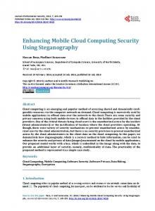
The University of Michigan - Dearborn The Electrical and Computer Engineering Department Dearborn, Michigan 48128 Abstract Cloud computing is a model for enabling ubiquitous, convenient, on-demand network access to a shared pool of configurable computing resources that can be rapidly provisioned and released with minimal management effort or service provider interaction [9]. As every technology in general, its benefits are associated with a variety of risks. Some of its major risks are security of data, authenticity, and protection. The objective of this paper is to come up with a robust and secure solution regarding the security of data in the cloud. Currently, there are many methods and provisions for cloud security but due to the "big data" nature of the cloud, most of them are software implementations [8]. In this paper we have implemented the Advanced Encryption Standard (AES) which is one of the most secure encryption algorithms using hardware. This solution provides one of the fastest and most secure methods to receive, transmit and store data. According to our results we are able to implement this solution 16.15 times faster than other software implementations and 51.5 times faster than other hardware implementations. Keywords: cloud computing, data security, advanced encryption standard, FPGA, hardware design 1- Introduction The Advanced Encryption Standard (AES) is one of the most secure encryption algorithms. This algorithm was developed by Joan Deamen and Vincent Rijmen [7], and it is selected to be a FIPS1 from NIST 2[6]. The algorithm is generally used for top secret data processing and storage. It is implemented in different sizes using common high level programming languages in standard architectures [2]. Figure 1 shows the block diagram of a 128-bit AES implementation. It requires a key and 128 bits of data as input and produces the encrypted/decrypted data and the associated key of the same size as an output. These data goes through a series of ten rounds (plus an initial round), where four different steps are performed within each round to transform the data. 1
Federal Information Processing Standard National Institute of Standards and Technology
2
Figure 1: Block Diagram of the AES implementation requirements
There are a number of software implementations for the AES algorithm. All of them have some advantages and disadvantages in terms of performance and reliability. Bernstein and Schwabe [3] presented an excellent job in comparing those implementations. There are few hardware implementations of the AES algorithm that are available. Marko Mali, Franc Novak and Anton Biasizzo [4] presented an optimized implementation method.
The paper is organized as follows: in section 2 we present our design version of the AES. Section 3 presents the hardware implementation for the design of the AES. Section 4 presents the VHDL implementation modules. Section 5 presents the Encryption/Decryption tests for the AES hardware system. Section 6 presents performance evaluation for the software and hardware implementation of this algorithm. Finally, section 7 presents conclusion and future work remarks.
o
Shift Rows: o
A shift operation of the data which arranges the data into a 4 X 4 byte matrix and shifts certain rows by a different offset. This keeps the columns in the data within the algorithm from becoming linearly independent.
o
2- Design Our version of the AES algorithm implementation is capable of encrypting 128 bit plaintext data into 128 bit cyphertext data after a series of ten rounds, as well as an initial round. Within each round, up to four specific operations are performed to change the data. Although this is a 128 bit algorithm, it can be easily converted to 192 or 256 bits. In order to return the original plaintext input from the encrypted cyphertext, a decryption process is performed. The decryption process similarly has eleven rounds. Each round of decryption has also up to four operations that are performed on the input data. The decryption operations are the inverse of the respected encryption operations because the goal is to return the data to its original state. Figure 2 shows the flowcharts for the encryption and decryption processes and their internal operations. When the data passes through the encryption stages, it is transformed into cyphertext and is locked by a key of equal size as the plaintext data (128 bits) using the following operations: o
Add Round Key: o
o
Adds the 128 bit Round Key with the 128 bit input via bitwise operation “XOR”.
Sub Bytes: o o
o
A substitution step where each byte of the input is replaced by another byte according to a lookup table. This Lookup table serves as a more efficient method; whereas, the Sub Bytes step is actually implemented by taking the multiplicative inverse of each byte over GF(28). This adds a nonlinear property to the encryption algorithm making it stronger against attacks.
Plain Text
Cypher Text
Add Round Key
Add Round Key
For: Round 1 to 10 LOOP
Inverse Shift Rows
For: Round 1 to 10 LOOP
Sub Bytes
Inverse Sub Bytes
Shift Rows Loop Loop
Mix Columns
NO
Add Round Key
Round 10?
Add Round Key
YES
Inverse Mix Columns
NO
Round 10? YES
End LOOP
Cypher Text
Plain Text
Figure 2: Flowchart for Encryption Process (Left) and Decryption Process (Right)
o
Mix Columns: o o
Matrix multiplication is performed on the data by performing bitwise multiplication on the 128 bit input and a constant 128 bit matrix. Adds diffusion to the cypher.
3- Hardware Implementation As seen from the design flowchart, this algorithm requires the data to go through a series of multiple round transformations, and each round has its own operations performed on the data. Each of these steps is also the core of our implementation, where the real data transformation occurs. The order in which they are performed is specified in the algorithm as shown in figure 2. In order to implement this hardware design, we used VHDL as a Hardware Descriptive Language. We approached this solution using a modular scheme, and
then implemented each of the parts using a bottom-up approach. Figure 3 provides a block diagram of the hardware implementation for the AES algorithm. AES Top-Level Control Data In
Data_Next (128)
Encryption Rounds
Encrypt (1)
Round Constant (8) Key_Select (8)
Key_Out (128)
Data Data_Out (128) Register
Control
Key Schedule Key_out (128)
Data Out
Data_Next (128)
Decryption Rounds
Decrypt Encrypt Reset
Decrypt (1)
Clock
Data_Select (2)
Key
Figure 3: Implementation Flowchart
The control module sends signals to control the progress and input of each round. After each round, the data is passed to the next round at the positive edge of the clock, and will receive new control signals. The key schedule will also have a new key created from the “Add Round Key” operation after each round. In this implementation we have combined structural and data flow designs with a variety of VHDL statements and structures. This was the main reason of increasing the performance, since most of the operations are executed concurrently. In order to synchronize the data between rounds we have also used procedural blocks.
encryption/decryption command and stores the results of an encryption or decryption process inside a clockcontrolled register. The top level module calls the following components:
Control Encryption Rounds Decryption Rounds Key Schedule
The encryption and decryption registers are loaded with new data on the positive edge of the clock. The data stored within these registers enters the encryption/decryption round components, which, in turn, create new data to be loaded into the registers at the end of the clock cycle. 4.2- Control The control unit is a linear state machine consisting of 13 states. Each state sends control signals to other components within the encryption/decryption algorithm in order for them to process data and interact properly. Figure 4 shows the flowchart of the Control Unit. Do Not Load Registers Initial State Encrypt/Decrypt Signal = ‘1’
Data/Key Registers Loaded Initial Round Executes New Round Constant
4- VHDL Modules The AES Encryption system has been divided into several modules. These modules act as layers where information is passed into one module from the previous, starting from the top_level implementation, and leading down to the specific encryption/decryption processes within each round. The top layer module as well as the control unit has control over the encryption and decryption sub-processes. Information is relayed to these sub-processes and their output is stored in a data register for the next round. More specific details describing the modules are as follows: 4.1- Top_Level The top level code is the main module for the AES algorithm. It accepts the input data, key, and the
Control
(Begin Rounds) Load data from previous Round . New Round Constant . ` . Stop Loading .Key Register No New Round Constants (End Rounds) Stop Loading Data Register Algorithm Finished
Load Inputs
YES
Round 0 ... Round 9
Limbo
IF Encrypt/Decrypt Signal = ‘0’ NO
Figure 4: Control Unit Flowchart
The Control Unit (CU) consists of the following states:
o
o
o
o
Initial State: o An infinite loop which waits for the „Encrypt‟ or „Decrypt‟ (E/D) signal. o Data register and Round Key register remain inactive until an E/D signal is active at the upper edge of the clock. Load Inputs State: o Data register and key register contains incoming key_in/data_in inputs. o Performs initial Encryption/Decryption round o Prepares the first new round_constant for the key generator. Round 0 – 9 states: o Data and round key registers are updated after each round with the results from the cypher operations. o A new round_constant is the output from each new round. o At Round 9 (the final round), signal Round10_Select is sent to ensure that the final mix_columns operation is not performed Limbo State: o Deactivate the data register from receiving new input. o The data register now contains the final results of the encryption/decryption. o Check for E/D signal.
The inputs to the key generator are as follows: o Input_Key: 128-bit input. o Key_Select: 1-bit select line that chooses whether to load user key into key register for initial round, or subsequent new keys for every round after that. o Load_Key: 1-bit input that enables/disables loading of key register o Round_Constant: 8-bit input generated by the control unit for every round. New Key
Input Key 1
0 2:1 MUX
Key_Select Round_Constant
Key Register
31:0
63:32
Load Key
95:64
127:96
4-Byte Left Shift
XOR XOR
4-Byte S_Box XOR
MSB
LSB
XOR XOR
4.3- Key_Generation The Key Generator produces a new round key for every round of the AES algorithm. These round keys are used for the “Add Round Key” stage within the algorithm, which is performed a total of 11 times. The key generator itself is very complex and involves splitting the input key into 4 separate 32-bit words and performs different operations on each separate word to produce a new key output. For the key generator we use the S_Box for a 4 byte operation. Figure 5 shows the flowchart for the encryption key generator. There is also an inverse key generator for the decryption process, which is very similar to the encryption version, except the order in which the 32-bit words are XOR‟ed is reversed.
Figure 5: Key Generator Flowchart(Encryption)
4.4- S_bytes Substitution boxes in this algorithm are two matrixes of data that are provided from the algorithm standard [2]. These matrixes are implemented in VHDL as look up tables. One matrix is used for the encryption process, while an Inverse_S_Box matrix is used for the decryption process. In order to have good memory management, we decided to implement the S_Box as a RAM memory. This allows us to have faster access and a better hardware realization. Due to the amount of data that S_box contains, C# programming language was used to generate the VHDL code for this part. Figure 6 shows the S_Box block diagram.
Figure 9:Mix_column operation (decryption)
Figure 6: S_Box Block diagram
4.5- Shift_Rows For the shift rows operation we transform 128 bits of data into a 16X16 bit matrix. For encryption, we rotate the second row left by one, the third row left by two and the forth one left by three. Similarly, for the decryption process we perform the same operation but instead of shifting left we shift right.
5- Encryption/decryption Test After the development of the project we were able to get impressive results even in different execution environments. The following table shows a set of data that goes through an encryption and a decryption process. It can be observed from table 1 that the data which comes out of the decryption (decrypted cyphertext) is identical to the data that goes into the encryption (plaintext). This is proof that the implementation of the algorithm is working correctly. Figures 10 and 11 provide additional details to the steps that the data goes through and how each round transforms the data for both processes.
Figure 7: Shift Rows for encryption (center) and decryption (right)[8]
4.6- Mix_Columns The mix_columns step is another operation which is performed within a round. This operation requires a matrix multiplication by two standard matrixes[5]. In our implementation, first we convert the data into a matrix and then we multiply it by the following hexadecimal numbers: 02, 03 for encryption and: 0E, 0B, 0D, 09 for decryption. After the multiplications we are able to build the resulting matrix by selecting the desired components. Figures 8 and 9 show an overview of the encryption and decryption operations, respectively.
Data_In Key_In Data_Out Key_Out
Encryption
Decryption
0011223344556677 8899AABBCCDDEEFF F0F0F0F0F0F0F0F0 F0F0F0F0F0F0F0F0 C7AD68D657BEFBE6 4F2ABA1ECDD7695B 4D59BD8605CC2080 57405E25359D5435
C7AD68D657BEFBE64F2A BA1ECDD7695B 4D59BD8605CC20805740 5E25359D5435 00112233445566778899 AABBCCDDEEFF F0F0F0F0F0F0F0F0F0F0 F0F0F0F0F0F0
Table 1: Encryption / Decryption Phases 1
2
4
3
Figure 10: Test Bench I/O results (Below) and Waveform (Above) 1
2
3
4
Figure 8: Mix_column operation (encryption)
Figure 11: Test Bench I/O results (Above) and Waveform (Below)
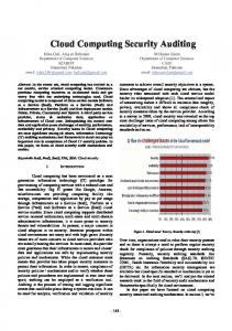
1. The „Encrypt‟ line input goes to logic „1‟, then Control unit gets activated 2. The Data and Key inputs are loaded into the data and key registers. The initial round is executed. 3. Series of 9 rounds execute sequentially 4. The final „Limbo‟ Round of encryption. The Cyphertext is now displayed as the output 6- Performance Evaluation This implementation is intended to be used in cloud computing applications, and execution time (encryption/decryption time) is the most important factor in these applications. In this section we will present a comparison between the software and hardware implementation of this algorithm in order to show the efficiency of our approach.
6.1- Software Performance of AES There are a number of software implementations for the AES algorithm. All of them have some advantages and disadvantages in terms of performance and reliability. Bernstein and Schwabe [3] presented an excellent job in comparing those implementations. One of the fastest software implementations that we found, is coded in C++ with Microsoft Visual C++ .NET 2003 and is compiled on a 2.1 GHz processor running in Windows XP SP1 [1]. In addition the paper [1] used 386 assembly routines for multiple-precision addition and subtraction and code optimization.
The 128 bit version of the AES algorithm was processes 61.010 Mb/s in their implementation [1]. The following shows the calculation time used to compute the encryption for 128 Bits: 61.010 Mb/s = 6.101 * 107 b/s 476640.625 Blocks/s 1 Block (128 bits) =2.1 μs
To evaluate our design we have used a Virtex-5 LX ML501 FPGA board. Table 2 shows the board‟s clock signals.
6.2- Other Hardware Implementations Few hardware implementations of the AES algorithm are available. Marko Mali, Franc Novak and Anton Biasizzo [4] presented an optimized implementation method as shown in table 4. Table 2:Virtex-5 LX ML501 FPGA clock signals [11]
We have utilized the single-ended clock with a frequency of 100 MHz at the AD8 pin and the hardware implementation results are given in table 3.
Table 3: Hardware Performance of AES on a Virtex5 FPGA board
Function
Time (μs)
Throughput(Mbit/s)
Cipher(encryption)
16.50
7.76
Inverse Cipher (decryption)
20.56
6.23
Table 4: Hardware performance [4]
This implementation runs on a Celoxica RC1000 hardware platform equipped with Xilinx Virtex family BG560. This is based on a clock rate of 74.4MHz. The frequency which is the main impact of the performance is about 25% lower than our frequency of 100MHz that was used with the Virtex-5. Our hardware implementation is 126.9 times faster in encryption and 158.1 times faster in decryption. If we take in consideration the PCI bus we are still 56.9 times faster in encryption and 70.9 times faster in decryption. To have a comparable comparison between our implementation and the implementation reported in [4] let us assume that we are decreasing our frequency to 74.4MHz to match the clock rate in [4]. Using the PCI bus we can achieve an execution time of 0.36μs this
way, which is still be 45.8 times faster in the encryption process and 57.1 times faster in the decryption process. 7- Conclusion In this paper we have presented a hardware implementation for the AES algorithm that is fast and suitable for cloud computing applications. The timing performance of our design and implementation of the AES was compared to other software and hardware implementations. Our FPGA hardware implementation was much faster than the Software implementation which was implemented on a processor witha frequency of 2.1 GHz (21 times faster than the frequency used in the FPGA for our hardware implementation). While we encrypted a block of 128 Bits in 0.13μsusing our FPGA hardware implementation with a frequency of 100 MHz, it took 2.1 μs to be encrypted with a software optimized implementation in a frequency of 2.1 GHz. Our proposed version of the hardware implementation is 16.15 times faster than that of the software optimized method. Our AES hardware design was also compared with other hardware performances of this encryption standard and with the same frequency and using the same PCI bus. We were able to get an average execution time of 51.5 times faster than the current one. From these results we have seen that there is a great potential for this project to be continued further and be applied to certain applications. An important aspect that we would want to look in the future is to deploy this implementation in real time environments and see its behavior. Various tools such as SoNIC developed at Cornell University would allow us to access the physical layer of the network. This way we can embed our solution into the lower levels of the network stack targeting a robust security solution in real time environments [10]. 8- References [1] Jain, Raj. "CSE567M: Computer Systems Analysis (2006, fall). CSE567M: Computer Systems Analysis (Fall 2006) [Online]. Available: http://cs.wustl.edu/~jain/cse567-06/ [2] Daemen, Joan; Rijmen, Vincent (9/04/2003). "AES Proposal: Rijndael". National Institute of Standards and Technology. p. 1. Retrieved 21 February 2013.
[3] Daniel J. Bernstein, Peter Schwabe. “New AES Software Speed Records”, in INDOCRYPT 2008, 9th International Conference on Cryptology in India, Kharagpur, India, December 14-17, 2008. Proceedings [4] Marko Mali, Franc Novak and Anton Biasizzo, ”Hardware implementation of AES algorithm”, Journal of ElectricalEngineering, Vol. 56, NO. 910, 2005, 265–269. [5] Xintong, Kit Choy. (2014, June 26).Understanding AES Mix-Columns Transformation Calculation [Online].Available:www.angelfire.com/biz7/atleast/ mix_columns.pdf [6] Gaithersburg, MD: Computer Security Division, Information Technology Laboratory, National Institute of Standards and Technology. (2001, November 26). Announcing the Advanced Encryption Standard (AES) [Online].Available: http://csrc.nist.gov/publications/fips/fips197/fips197.pdf [7] J.Daemen and V. Rijmen. (1999, September 3).AES Proposal: Rijndael, AES Algorithm Submission [Online]. Available:http://csrc.nist.gov/publications/fips/fips1 97/fips-197.pdf [8] Gürkaynak, Frank K. (2006, December 20).GALS System Design: Side Channel Attack Secure Cryptographic Accelerators [Online]. Available: http://www.iis.ee.ethz.ch/~kgf/acacia/c3.html [9] Mell, Peter and Grance, Timothy. (2011 September).The NIST Definition of Cloud Computing [Online]. Available: http://csrc.nist.gov/publications/nistpubs/800145/SP800-145.pdf [10] Lee Suh, Ky Wang Han and Hakim Weatherspoon, (2013 May), SoNIC: Precise Realtime Software Access and Control of Wired Networks, [Paper] Available:https://www.usenix.org/system/files/conf erence/nsdi13/nsdi13-final138.pdf [11] Xilinx, Inc. (2014). Virtex-5 LX FPGA ML501 Evaluation Platform [Online]. Available: http://www.xilinx.com/products/boards-andkits/HW-V5-ML501-UNI-G.htm