ples 37], 15], 32], regions are characterized by their spa- tial homogeneity .... the projected partition plus a set of hierarchical partitions that are \above" and ...
60
IEEE TRANSACTIONS ON CIRCUITS AND SYSTEMS FOR VIDEO TECHNOLOGY, VOL. 7, NO. 1, FEBRUARY 1997
Segmentation-based Video Coding System Allowing the Manipulation of Objects
Philippe Salembier, Ferran Marqu�es, Montse Pard�as, Ramon Morros, Isabelle Corset, Sylvie Jeannin, Lionel Bouchard, Fernand Meyer, and Beatriz Marcotegui Abstract | This paper presents a generic video coding al� The representation of objects by partitions does not gorithm allowing the content-based manipulation of objects. only involve the de nition of the objects contours at This manipulation is possible thanks to the de nition of a one time instant but also their time evolution. Indeed, spatio-temporal segmentation of the sequences. The coding region or object tracking is mandatory for a large numstrategy relies on a joint optimization in the Rate-Distortion sense of the partition de nition and of the coding techniques ber of content-based functionalities [18]. This requireto be used within each region. This optimization creates the ments eliminates all techniques that de ne partitions link between the analysis and synthesis parts of the coder. independently from one frame to another one. The analysis de nes the time evolution of the partition, as well as the elimination or the appearance of regions that are � The representation cannot rely on a xed topology of homogeneous either spatially or in motion. The coding of the partition. Indeed, the partition has to evolve with the texture as well as of the partition relies on region-based the modi cations of the scene content: regions are to motion compensation techniques. The algorithm o�ers a be introduced or removed in the partition when new good compromise between the ability to track and manipulate objects and the coding e�ciency. objects appear or disappear in the scene. Keywords | Video coding, Region-based coding, SpatioCoding algorithms following this strategy can be viewed temporal segmentation, Rate-distortion optimization, A�ne motion estimation and compensation. as second generation coding approaches [11]. Examples of region-based video coding schemes can be found in [19], [37], [4], [15], [9], [3], [32]. The main di�erence between I. Introduction these techniques is the relative importance they assign to ONTENT-BASED representation and coding of the the spatial or the motion information. In a rst set of examvisual information is currently becoming an extremely ples [37], [15], [32], regions are characterized by their spaactive eld of research. An important part of this rese- tial homogeneity, whereas in a second set [19], [4], motion arch is stimulated by some of the MPEG-4 activities that information is used as the main homogeneity criterion. Fitry to provide technical solutions to emerging needs of ap- nally, examples of segmentation techniques involving both plications such as interactive video services, video mobile criteria can be found in [9], [3]. This last approach o�ers a terminals, remote control, etc. In a large number of these large number of advantages: the spatial homogeneity criapplications, there is a need to have a content-based re- terion allows a very accurate de nition of the regions and presentation of the sequence instead of a more traditional the processing of generic sequences because, for example, pixel-based or block-based representation. One way of fa- it can deal with the appearance of new objects. The mocing this problem is to rely on signal-dependent partitions tion homogeneity criterion is important to limit the number of the sequence where regions ideally de ne the various of regions and therefore the coding cost associated to the objects of the scene. Then, all processing steps, including partition. This limitation is generally obtained by merging representation, processing, coding or manipulation, rely on spatial regions that can be processed, that is compensated, these regions. together. De ning a content-based representation of sequences by All these techniques have the same structure involving means of partitions has at least three consequences: an analysis phase (mainly the segmentation) followed by a � The signal-dependent partition results from an analy- synthesis step (mainly the coding functions). In most of sis of the sequence. In particular, a priori de ned par- them, there is no strong relation between the two steps. titions such as block partitions are not suitable. One tries to obtain the \best" segmentation, on the one hand side, and then, to code the partition as well as the texture with the lowest possible amount of bits, on the Manuscript received March 10, 1996; revised July 1, 1996. This paper was recommended by Guest Editors Y.-Q. Zhang, F. Pereira, other hand side. However, high coding e�ciency requires a T. Sikora, and C. Reader. This work has been supported by the strong interaction between the analysis and synthesis steps. European Community through the RACE MAVT and MORPHECO Indeed, the de nition of the partition should depend on projects P. Salembier, F. Marqu�es, M. Pard�as, and R. Morros are with the the techniques used to code the various regions. Based on the work done for bit allocation reported in [34], [20], Polytechnic University of Catalonia, 08034 Barcelona, Spain. I. Corset, S. Jeannin, and L. Bouchard are with Philips Research [25], a solution for an optimal de nition of a partition and Lab., Limeil-Br�evannes 94453, France. F. Meyer and B. Marcotegui are with Paris School of Mines, 77305 of the set of coding techniques to be used in each region is proposed in [26]. However, in this work, the partitions Fontainebleau, France. Publisher Item Identi er S 1051-8215(97)00884-7. are de ned for each frame independently of the previous
C
SALEMBIER ET AL.: SEGMENTATION-BASED VIDEO CODING SYSTEM ALLOWING THE MANIPULATION OF OBJECTS
partitions. Therefore, there is no time tracking possibility of the regions and the scheme is not really suitable for an e�cient manipulation of objects. This paper describes a video coding system that combines the advantages of the approaches mentioned above in order to allow an e�cient manipulation of objects. The main features of the proposed algorithm are the following: 1) the segmentation involves both spatial and motion homogeneity criteria, 2) the time evolution of each region is de ned (time tracking), 3) the de nition of the coding strategy involves a global optimization of the partition as well as of the coding technique for each region. Moreover, the scheme is quite exible and open to the integration and comparison of new tools. A rst version of the algorithm has been proposed within the framework of MPEG-4 under the name of SESAME. A detailed description of the algorithm and of its hardware complexity can be found in [6]. The organization of this paper is as follows: Section 2 describes the encoding algorithm and gives some details on the main processing steps. Section 3 is devoted to coding results and discusses the possible use of the algorithm for building new content-based functionalities. Finally, conclusions and open issues are reported in section 4. II. Coding Algorithm
A. Structure of the algorithm The objective of this section is to give an overview of the algorithm and to describe the basic coding strategy. The block diagram corresponding to the encoding process is presented in Fig. 1. The encoding process relies on three sets of functions: Bit Allocation Function, Partition Functions and Coding Functions: Bit Allocation Function: This function, corresponding to the Decision block of Fig. 1, makes the link between the analysis (partition functions) and the synthesis (coding functions) parts of the encoder. As discussed in the introduction, an e�cient content-based representation relies on a careful study of the bit allocation problem. The objective is to share a given number of bits between the various types of information to be coded and transmitted (motion, partition, gray level and color). As a result, the Decision block de nes the coding strategy, that is the set of regions to be coded as well as the type of coding technique to be used in each region. The coding strategy results from the optimum (in the Rate-Distortion sense) selection of regions and coding techniques out of a set of possible regions and coding techniques. Partition Functions: The objective of this set of functions is to create for each frame a universe of possible regions out of which the Decision has to create the nal partition. Note that, to be able to track objects, this universe of regions should be related to the previous partition. This is the objective of the Projection block of Fig. 1. Moreover, the universe of regions has to o�er to the Decision the possibility to introduce new
Decision
Partition Tree
Bit Allocation Function
61
Decision coding
Motion coding
Time T
Projection
Partition coding
Time T-1
Texture coding Partition Functions
Coding Functions
Fig. 1. Description of the encoding processing steps
regions or to eliminate past regions. This function is achieved by the Partition Tree block. Coding Functions: The last set of functions actually codes the information necessary to restore the sequence on the receiver side. It deals with the encoding of the coding strategy (Decision coding), the motion information (Motion coding), the partition (Partition coding) and the pixel values (Gray level & color) called Texture in the sequel. To have an e�cient representation, both the partition and the texture are motion compensated. This explains why the Motion coding block is located before the Partition and Texture coding blocks. In the sequel, the various processing steps are further explained and discussed. Projection block: The objective of this block is to de ne the time evolution of the regions. To limit as much as possible the processing delay and the computational load, only the previous coded frame and its partition at time T ? 1 are used to de ne the time evolution of the partition at time T . This step is purely a region tracking step [22] and, in particular new regions cannot be introduced. Note, however, that some regions may disappear. The projection block will be more precisely described in section II-B. Partition Tree block: The main objective of this block is to create the universe of regions out of which the Decision has to create the nal partition. Assume, in a rst step, a situation where the scene content is not strongly modi ed from one frame to the next one. In this case, the partition as de ned by the Projection, called the projected partition in the sequel, is a rather good approximation of the optimal partition of the current frame. However, some new objects may have appeared in the scene and new regions may need to be introduced. On the other hand side, seve-
IEEE TRANSACTIONS ON CIRCUITS AND SYSTEMS FOR VIDEO TECHNOLOGY, VOL. 7, NO. 1, FEBRUARY 1997 Upper levels
62
Merging
Lower levels
Projected partition
Segmentation
Fig. 2. Structure of the Partition Tree
ral regions belonging to the same object can be processed globally because, for example, they have the same motion. In this case, these regions can be merged to create one single object and to decrease the coding cost devoted to the partition. In conclusion, some uctuations with respect to the projected partition must be allowed. The concept of Partition Tree [24] can be used to deal with these uctuations. As illustrated in Fig. 2, the Partition Tree is formed by the projected partition plus a set of hierarchical partitions that are \above" and \below" the projected partition. Below the projected partition, several levels of ner partitions are created. The partitions are ner in the sense that they involve a larger number of regions and that the contours present at a given level are also present at lower levels. This procedure can be viewed as a hierarchical segmentation that splits the regions of a given level to produce the regions of the next lower level [27]. Note that the procedure is purely spatial: it does not take into account any motion information. Above the projected partition, several levels of coarser partitions are created. Here, regions are merged if they can be processed globally: this reduces the partition coding cost and goes closer to the notion of objects. In practice, following a motion homogeneity criterion, regions are successively merged to create coarser partitions. In section III, we will see how this initial merging strategy can be modi ed to deal with speci c content-based functionalities. As can be seen, the Partition Tree de nes the universe of possible regions issued from the projected partition. These regions can be homogeneous either spatially (lower levels of the tree) or in motion (upper levels of the tree). No decision is made concerning the actual partition to be coded. The objective is simply to de ne a reduced set of regions that are likely to be part of the optimum partition. Finally, let us mention that, besides the de nition of the universe of regions, the Partition Tree block also includes the estimation of the motion parameters for all regions in the tree. This estimation is necessary for the creation of the upper levels of the tree and also for the Decision. Section II-C discusses more precisely the creation of this tree. Decision block: As previously discussed, based on the Rate-Distortion criterion, the Decision block selects the
best strategy in terms of regions and coding techniques among a set of possibilities [26], [17]. The Partition Tree contains all regions that may belong to the nal partition; for each of them, a set of possible coding techniques is proposed to the Decision. This last set involves several regionbased coding techniques with various levels of quality. Moreover, the techniques can be proposed in intra-frame mode (coding of the original signal) and in inter-frame mode (motion compensation of the region and coding of the prediction error). Fig. 3 summarizes the decision process: from the Partition Tree, all regions are extracted to form the Decision Tree. Several region coding techniques (de ned by the set of coding techniques fC1,...,Cng are considered for each region. Then, taking regions from various levels of the Partition Tree, the Decision block de nes jointly the best partition and the best coding technique for each region. More details about this block can be found in section II-D. Coding blocks: Once the optimum partition and the coding strategy have been chosen, the information necessary to decode the sequence is sent to the receiver. This information is composed of the coding strategy itself, the motion parameters for the regions that should be compensated, the partition and, nally, the texture parameters of each region. A large set of coding techniques can be used. Sections II-E and II-F describe more precisely the various techniques that have actually been used. Intra-frame mode of transmission is necessary to initiate the coding process and to periodically refresh the information at the receiver side. The description previously given assumed an inter-frame mode of coding. For the intra-frame mode, two modi cations have to be introduced: First, the Projection does not rely on the previously coded partition. Therefore, this step is replaced by a simple initial segmentation of the frame. Second, the Decision process optimizes the coding strategy on the basis of the Partition Tree and of only intra-frame coding techniques. B. Projection The partition projection adapts the partition PT ?1 of frame T ? 1 to the current frame [32]. PT ?1 is the partition chosen by the decision for representing the previous image. The projection procedure accommodates PT ?1 to the data of image T, without introducing new regions. In the projection algorithm, the region correspondence problem can be solved using connectivity and motion criteria [22], [21]. The projection is performed in two steps. First, motion is estimated between the original frames T ?1 and T , and the previous partition is motion compensated. Then, the de nition of regions into the current frame is achieved by a 3D watershed algorithm [16] which is essentially a morphological region growing algorithm that extends the compensated past regions (called markers) into the current frame. In the work presented in [21], the compensated regions used as markers and extended by the watershed algorithm are assumed to be spatially homogeneous. This assumption cannot be made now because partitions are formed by
SALEMBIER ET AL.: SEGMENTATION-BASED VIDEO CODING SYSTEM ALLOWING THE MANIPULATION OF OBJECTS
63
Set of coding techniques {C1,C2,...,Cn} Best coding techniques C3
C3 Selection of regions
Analysis
C1 C1 C3 C1
Partition Tree
Decision Tree
Final Partition
Partition at time T-1
Projected Partition at time T
Projection
Fine Partition
Merging + cleaning
Resegmentation
Fig. 3. Decision process
Fine Projected Partition
Fig. 4. Example of projection
regions that maybe homogeneous either in gray level or in motion. To solve this problem, the Projection block uses a double partition approach [13]. In this approach, two different levels of partition are de ned. The partition of the previous image PT ?1 is re-segmented in order to achieve a ner partition as shown in Fig. 4. This ne partition contains a larger number of regions which are obtained by re-segmenting the regions in PT ?1 following spatial criteria. The objective is to guarantee the spatial homogeneity of each region. This ne segmentation is then projected in the current frame in order to obtain a ne segmentation at time T . As mentioned previously, a 3D watershed algorithm is used for this ne partition projection [16], [21]. The algorithm can be seen as a region growing technique that progressively assigns pixels pi to regions Rj . The assignation order is de ned by a cost function assessing the \distance" between pixel pi and region Rj . The cost of assigning a pixel pi to a region Rj uses three di�erent types of information:
mation information, respectively. The function distt computes the di�erence between the gray level value of a pixel pi with respect to the mean value of a region Rj . In turn, the function distc is related to the increase in contour complexity of a region Rj if a pixel pi is added to it. Finally, the function distd measures the deformation of a region Rj with respect to the projected marker when adding a pixel pi to it. The use of this cost function provides a good stability of the labels through the time domain and, therefore, allows an e�cient tracking of the objects [12].
In order to obtain the partition PT , only those contours of the ne projected partition associated to the coarse partition have to be kept. This can be easily done since the projection algorithm keeps track of the labels of each region. Therefore, the projection of a region from the coarse partition can be obtained by merging the projections of the regions that belong to it at time T ; that is, by re-labeling the ne projected partition. However, the projection and re-labeling of the ne partition does not ensure that an actual partition is obtained. Indeed, unconnected regions Cost(pi ; Rj ) = �1 distt (pi ; Rj ) + �2 distc (pi ; Rj ) (1) may have the same label after relabeling. This problem is solved by a cleaning step that keeps the largest connected +�3 distd(pi ; Rj ) component for each label and removes the other connecThe three functions distt , distc and distd are the distan- ted components with the same label. A pure 2D watershed ces related to the texture, contour complexity and defor- algorithm is applied to obtain the nal partition. The com-
64
IEEE TRANSACTIONS ON CIRCUITS AND SYSTEMS FOR VIDEO TECHNOLOGY, VOL. 7, NO. 1, FEBRUARY 1997
plete procedure is illustrated in Fig. 4, where the evolution each region called \residue", 2) the simpli cation of the reof a region is shown. sidue by \connected operators" [31], 3) a marker extraction step and 4) nally a watershed algorithm [16]. In our impleC. Partition tree and Motion estimation mentation, all segmentation steps are size-oriented except 1) Creation of the partition tree: The objective of the the last one which is contrast-oriented (see [27], [30], [32], Partition Tree is to de ne a universe of regions for the Deci- [24] for more details). One of the advantages of this segsion. To limit the complexity of the Decision, this universe mentation procedure is that it gives good results at a low should be of reasonable size and structured in a hierarchical computational cost. 2) Motion estimation: As mentioned previously, the way [24]. This goal can be achieved by creating uctuations motion of each region of the Partition Tree has to be estiaround the projected partition: lower levels are generated by successive hierarchical segmentation steps [27], [32] and mated for the merging steps and for the Decision. a) Motion representation: The motion of each region is upper level are obtained by successive merging. a) Merging procedure: On the upper levels of the Par- represented by a polynomial model. A simple translatiotition Tree, coarser partitions are created by merging steps nal model is generally not su�cient for regions of medium following a motion criterion. The aim is to merge neigh- or large size. Parametric motion models [7], [36] are able boring regions that have a similar motion. Indeed, if these to give a region-based motion representation that is both regions can be compensated using the same motion pa- compact and able to deal with quite complex motions. In practice, on each region X of the Partition Tree, the rameters, the contour between them does not need to be coded and only one set of motion parameters is needed. motion between previous (T ? 1) and current (T ) frames The merging procedure is iterative: starting from the pro- is assumed to be a�ne, i.e. de ned by two polynomials of jected partition, a rst coarser partition is created. Then, order one: starting from this partition, a new coarser partition is credx = a + bx + cy; dy = d + ex + fy (2) ated. This process is repeated up to the highest level of where (dx; dy) is the motion of pixel (x; y) between T ? 1 the Partition Tree. At each level, before the merging itself, the motion of and T . This model can handle translations and simple each region is estimated. This procedure will be detailed rotations of any planar facet. Of course, to avoid expanding in section II-C. It results in a set of six parameters de ning the bit rate by using models that are more complex than an a�ne transformation for each region. Then, a Region needed on some regions (either very small or with simple Adjacency Graph (RAG) is constructed. Each node of the motion), the model complexity is adapted to the region it RAG represents a region and the edges of the graph indi- characterizes. b) Estimation process: The estimation of the model cate the neighboring relationship between regions. The edges of the RAG are valued by assigning to them parameter is done assuming constancy of the luminance a merging cost that estimates the motion di�erence of two along the regions trajectories [36]: regions. The cost that has been used is the increase of Mean I (x; y; T ) = I (x ? dx; y ? dy; T ? 1); (3) Square Error (MSE) in the compensation of the union of the two regions (with the motion parameters of the region where I (x; y; T ) denotes the intensity value at location giving the lowest MSE) with respect to the MSE obtained (x; y) at time T . when the two regions are compensated separately. Finally, The estimation itself is done by di�erential methods [33]. a given number of merging steps is performed by selecting The objective function is the MSE between the original rein the RAG the required number of edges with lower cost. gion and its current prediction. The Gauss-Newton method b) Re-segmentation procedure: The lower levels of the is used as minimization algorithm. This method iteratively Partition Tree are created by re-segmenting the regions of minimizes the region MSE by following the direction of its the projected partition. This segmentation creates new re- gradient that has been locally linearized. This approach gions that can represent new objects appearing in the scene, represents a good trade-o� between complexity and reliaor objects with several components that have been previ- bility. After the nal step of the minimization a spatial ously merged together but are starting to undergo di�erent relaxation is performed. It relies on a locally controlled motions. In both cases, we need to separate regions with a propagation of the current motions parameters to neighspatial criterion. bor regions. As the merging, the segmentation is iterative and proc) Estimation framework: It is well known that gressively builds the lower levels of the Partition Tree by gradient-based minimization methods do not insure the performing several hierarchical segmentation. Note that convergence toward the absolute minimum. The situation the problem is similar to the one of creating the ne par- is even worse here because regions are of arbitrary size and tition in the projection step, but the procedure has to be the sharp gray level transitions, that are of great help for done now in a hierarchical way. The morphological appro- the convergence, correspond most of the time to the borach described in [27], [30], [32] is particularly suitable for ders of the regions and are therefore di�cult to exploit. To this step: without getting into details let us mention that improve the behavior of the algorithm, the minimization this segmentation approach involves 1) the computation of process is carefully initialized and, furthermore, embedded the di�erence between the original frame and the mean of in a multi-resolution framework.
SALEMBIER ET AL.: SEGMENTATION-BASED VIDEO CODING SYSTEM ALLOWING THE MANIPULATION OF OBJECTS
65
Partition Tree Decision Tree Rate list: {R1,R2,...,Rn} Dist list: {D1,D2,...,Dn} projected partition
{R1,...,Rn} {D1,...,Dn}
{R1,...,Rn} {D1,...,Dn} {R1,...} {D1,...} {.} {.}
{.} {.}
{.} {.}
{R1,...} {D1,...} {.} {.}
{.} {.}
{.} {.}
{.} {.}
{R1,...} {D1,...}
{R1,...} {D1,...}
{.} {.}
{.} {.}
{.} {.}
{.} {.}
{.} {.}
{.} {.}
{.} {.}
{.} {.}
{.} {.}
{.} {.}
Set of coding techniques {C1,C2,...,Cn}
Fig. 5. Construction of the Decision Tree
For each region, the initialization tests several sets of motion parameters and selects the one that produces the lowest MSE. In particular the set of parameters estimated for this region in the previous frame (this is possible thanks to the time tracking ability of the system), as well as the set of parameters of regions located at the same position but on other levels of the Partition Tree are tested. Finally, the estimation is done following a multi-scale coarse-to- ne strategy based on a Gaussian pyramid. D. Decision The goal of the Decision step is to select the best coding strategy among a set of possibilities that are represented by the Partition Tree and a list of coding techniques. The Partition Tree de nes the set of regions out of which the algorithm should create the nal partition. The list of coding techniques de nes not only the type of techniques, but also their parameters (for example quantization steps), and the intra-frame or inter-frame mode choice. To limit the processing delay, the strategy is optimized for each frame separately. The Decision process relies on the concept of Decision Tree [26], [17] illustrated on Fig. 5. This tree concentrates in a compact and hierarchical structure all the possible coding choices. The Partition Tree de nes the choices in terms of regions. The list of coding techniques deals with the actual coding of these regions. The structure of the Decision Tree is de ned by the Partition Tree: each node of the Decision Tree corresponds to a region in the Partition Tree. The relations Father/Children between the nodes are also given by the Partition Tree and de ne how one region at a given level may either be split in various regions (Children) or be merged to form a larger region (Father). To de ne the coding strategy in the RateDistortion sense, the Decision Tree should also convey the information about the coding cost (Rate measured in num-
ber of bits) and quality (Distortion assessed by the Squared Error) of all possible coding techniques. Therefore, a list of rates (\Rate list" in Fig. 5) and a list of distortion (\Dist list" in Fig. 5) are assigned to each node. In practice, each region of the Partition Tree is coded by all techniques (with various quality levels and either in intra-frame mode or in inter-frame mode) and the corresponding rate and distortion values are stored in the Decision Tree. The computation of the distortion is rather straightforward. We have used the Squared Error between the original and coded frames (that is the sum of squared di�erence between the values of the original and coded frames for all pixel belonging to the region support). The situation is however more complex for the computation of the rate. Indeed the rate associated to a region is composed of the sum of the number of bits devoted to the texture, the motion as well as the shape information. In practice, the texture and the motion information is coded independently for each region so there is no major di�culty to de ne the texture or the motion rate for each region. But this independence is not maintained for the shape information because a contour is always shared by two regions. In order to avoid the problem of optimization with complex dependency between regions, we have used the following approximation of the shape rate: based on the analysis of a large number of coded frames, an average number of bit per contour points has been computed and the shape rate assigned to a region is equal to this average gure multiplied by the region perimeter divided by two (each contour point is shared by two regions). Finally, note that this step of construction of the Decision Tree is simply a phase of evaluation of the respective merits of each technique and no decision is taken. The optimization relies on the technique discussed in [20], [25], [26]. The problem can be formulated as the minimization of the distortion D of the image with the restric-
66
IEEE TRANSACTIONS ON CIRCUITS AND SYSTEMS FOR VIDEO TECHNOLOGY, VOL. 7, NO. 1, FEBRUARY 1997
tion that the total cost R is below a given budget (de ned for each frame). It has been shown that this problem can be reformulated as the minimization of the Lagrangian: D + �R where � is the so-called Lagrange parameter. Both problems have the same solution if we nd �� such that R is equal (or very close) to the budget. Therefore, the problem consists in using the Decision Tree to nd a set of regions creating a partition and a set of coding techniques minimizing D + �� R. Assume in a rst step that the optimum �� is known. How can the best set of regions and coding techniques be selected? � The rst step is to make a local analysis and to compute, for each node, the Lagrangian for each coding technique. The technique giving the minimum Lagrangian is considered as the optimum one for this node and this Lagrangian is stored. � The second step is to de ne the best partition. This can be done by a bottom-up analysis of the Decision Tree. Starting from the lowest level, one checks if it is better to code the area represented by a set of children regions as a single region SX or as a set of individual regions fxi gi with X = xi . The selection of the best choice is done by comparing the Lagrangian of X with the sum of the Lagrangians of xi . If the former is lower than the latter, the node corresponding to X is activated and the children nodes are deactivated. This procedure is iterated up to the root node. Note that, to use this approach the distortion should be additive over the regions. In our experiments, the Squared Error has been used, however, any additive measure can be used. Moreover, it should be noticed that the approach highly relies on the hierarchical structure of the regions in the Partition Tree. At the end of the procedure, the best partition is de ned the regions corresponding to the activated nodes together with their corresponding best coding technique (de ned during the rst step of the algorithm). The de nition of the optimum � parameter can be done with a gradient search algorithm. The algorithm starts with one very high value �h (1020) and one very low value �l (0) of �. For each value of �, the optimization procedure described above is performed. This results in two coding strategies (partition and coding techniques) that should give rates Rh and Rl respectively below and above the budget. If none of these rates is close enough to the budget, a new Lagrange parameter is de ned as � = (Dh ? Dl )=(Rl ? Rh ). The procedure is iterated until the rate gets close enough to the budget. In this formulation of the optimization problem, the main parameter is the budget that is assumed to be given for each frame. Based on this budget, the algorithm nds the coding strategy that minimizes the distortion. In practice, this procedure creates a coded sequence with a variable quality. The same structure can be used to de ne a coding strategy leading to constant quality sequences. The only modi cation consists in de ning a target distortion value for each frame and in inverting the role of D and R in the previous explanation. In this last case, the decision
Partition
Motion
Partition compensation
-
+
+ Partition memory
Error simplification
+
Error coding
Fig. 6. Motion compensation loop for partition coding
minimizes the coding cost to reach a given distortion. However, in practice, an intermediate solution may be used. Indeed, working at a xed cost per frame may produce some frames of very poor quality (scene changes, complex motion). Most of the time, it is more e�cient to spend more bits for these frames so that the quality is not too low and that it may be possible to use these frames for the compensation of future frames. Therefore, the optimization works basically on a xed nominal budget, but a minimum signal to noise ratio for each frame is de ned. If this minimum signal to noise ratio is not reached with the nominal budget, the budget is progressively increased. The procedure is stopped when the decision has found the optimum strategy: 1) the distortion is minimal, 2) the budget is at least equal to the nominal budget and 3) the signal to noise ratio is above a given threshold. E. Partition compensation and coding 1) Compensation of partitions: This section describes the coding of the partition sequence. The information to be transmitted to the receiver is made of three components: the shape (contour), the position, and the label of each region. To e�ciently transmit this information, the basic coding strategy for partition coding relies on motion compensation [28], [29]. This approach is similar to the one classically used for texture motion compensation, but it is applied here on the partition information, that is on an image of labels. Therefore, as illustrated in Fig. 6, the partition coding involves the prediction by motion compensation, the computation of the prediction error, the simpli cation of the error, and the coding of the simpli ed error. Before compensation, the motion parameters of the various regions of the current partition have been estimated in a backward mode. This step has been achieved in the Partition Tree block. The rst problem to solve is to de ne what kind of information can be used to motion compensate the partition. Indeed, the motion of the pixels inside a region (texture motion) may not be equivalent to the motion of its shape. Both motions coincide in the case of a rigid foreground region. But, for instance, this is not the case for a background region because the modi cations of its shape or of its contours are de ned by the motion of the regions in its foreground. However, the texture motion can be used to compensate both the partition and the texture if an extra information called the order is transmitted with the motion parameters [23]. The compensation itself can work in either a forward or
SALEMBIER ET AL.: SEGMENTATION-BASED VIDEO CODING SYSTEM ALLOWING THE MANIPULATION OF OBJECTS rec(T-1) 1
2
67
rec(T) C
invalid comp.
Empty area
B
invalid comp.
A
Overlapping area
Motion vector defined by {mot1} Motion vector defined by {mot2}
Fig. 7. Backward motion compensation of partition
a backward mode. The second mode is generally more simple and is assumed in the following [28]. Let seg(T ) and rec(T ) denote the original (as de ned by the Decision) and coded partitions at time T . In general, the partition coding is lossy, therefore, rec(T ) 6= seg(T ). The backward mode is illustrated in Fig. 7. It is a backward mode in the sense that, for each pixel of rec(T ), one tries to nd its label in rec(T ? 1). In this case, the main problem is to de ne which motion vector has to be used when the pixel (i; j ) of rec(T ) is considered. Indeed, at this stage, the receiver knows the set of motion parameters for each region, but not the current partition. Therefore, it does not know the region the pixel belongs to and it cannot select its corresponding motion parameters. The solution consists in considering at each pixel location all possible vectors de ned by all possible regions. In the case of Fig. 7, there are two regions; therefore, two set of motion parameters are considered for each point: one given by the parameters assigned to region 1 fmot1g and one given by the parameters assigned to region 2 fmot2g. Each time a vector de ned by the motion parameters of region n does not point to a pixel belonging to region n in rec(T ? 1), the compensation is invalid and discarded. In Fig. 7, this is the case for one of the two vectors used for points A and C. However, after each point has been considered, some pixels have no valid compensation (empty areas) and some others have more than one candidate (overlapping areas, see point B of Fig. 7). To solve the con icts of overlapping areas, an extra information called the order [23] is used. The order information de nes which region is considered to be in the foreground of which region. In case of con icts between labels, the foreground region gives the correct label. The reader is referred to [28], [29] for the detailed description of order estimation algorithms. The problem of overlapping areas is in practice quite important when using a�ne motion models. However, the use of the texture motion and of the order is a quite e�cient solution, because the texture motion information lead to a good compensation of the texture, and the order only represents a small amount of information necessary to compensate the partition. The order information is also useful for content-based representation implying multi-layer representations. Finally, the empty areas are left without label and are processed as compensation errors. 2) Coding of the partition: Once the order has been estimated, the coding of the partition can be done. The
Code intraregions
Compensate Partition
Code interregions
Fig. 8. Structure of the partition coding
structure of the partition encoding process is illustrated by Fig. 8. First, all regions that have to be sent using the intraframe mode of the partition coding are processed. These regions are either regions that have no motion parameters because the Decision has de ned an intra-frame mode for texture coding or regions that produce very large shape errors if they are compensated. The second step consists in computing a partition involving both the regions sent in intra-frame mode and the compensated regions. Finally, the partition errors are extracted, simpli ed, and coded. In the sequel, we describe brie y these three blocks (see [28], [29] for more details). a) Code intra-regions: The objective of this block is twofold: rst, to send the contour information of the regions transmitted in intra-frame mode and second, to create a binary mask de ning where the partition is considered as being already de ned. During the compensation, each time a label is compensated at a location corresponding to a region transmitted in intra-frame mode, the compensated label is not taken into account. For the coding itself, almost all partition coding techniques (lossy or lossless) may be used (see [29]). In our implementation, the modi ed chain code described in [14] has been used. This coding step allows the restoration on the receiver side of the contours of the intra-regions. However, it does not say which regions are transmitted in intra-frame mode. To actually create the binary mask at the receiver side, a binary code is sent for each region. b) Compensate partition: The compensation of the previous partition is done as described in Fig. 7. In case of con ict between several labels, a decision is taken on the basis of the order information. At the end, the compensated information is post-processed in order to create a partition where each region is made of only one connected component (cleaning step). c) Code inter-regions: The partition encoding in interframe mode consists in computing the error of the compensated partition, in simplifying this error, and in sending the information about the contours and labels of this error. 1. Compute error partition: The error computation consists in extracting the pixel locations where the compensated label is di�erent from the label of the partition de ned by the Decision. This results in an error mask. 2. Simplify error partition: This step introduces the losses in the coding process. Each region of the error mask is examined to know whether it has to be preserved and coded or discarded. In practice, two criteria can be used: (a) geometrical criterion: an error region is discarded if its size is smaller than a given size,
68
IEEE TRANSACTIONS ON CIRCUITS AND SYSTEMS FOR VIDEO TECHNOLOGY, VOL. 7, NO. 1, FEBRUARY 1997
Previously coded frame
Level 5
Level 4
Projected partition Partition Tree
Level 2
Level 1
Original frame Final partition Coded frame Fig. 9. Example of inter-frame processing
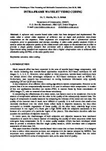
Fig. 10. Coding results for the Foreman sequence coded at 42 Kbits/s and 5 frames/s. First row: original frames 0, 115 and 235. Second row: coded frames
(b) gray level criterion: an error region is discarded if its use in the coding does not introduce a strong modi cation of the gray level (or color) values. 3. Code error contour: The actual coding of the error is done in two steps. The rst step consists in coding the contours of the error regions. It relies on a di�erential coding of the contours. Indeed, the receiver already knows the contours that correspond to the compensated partition. Therefore, only the new contours have to be sent. Coding techniques similar to the one used for the intra-frame mode can be used. The resulting partition can be seen as an over-partition because it involves contours of the compensated partition and of
the segmentation. The second step is to send the label of each region of the over-partition. First, the labels assigned on the receiver side are extracted. They correspond to the labels that were de ned by the compensation process. Second, the most probable labels of each region are estimated. Note that, because of the simpli cation step, each region of the over-partition may involve several labels of partition to code. The most probable label is de ned as the label that has the highest number of pixels in the considered region. The labels can be sent directly in the transmission channel but, in general, this would result in an excessive amount of informa-
SALEMBIER ET AL.: SEGMENTATION-BASED VIDEO CODING SYSTEM ALLOWING THE MANIPULATION OF OBJECTS
33 32:5 32 31:5 PSNR (dB) 31 30:5 30 29:5 29
69
18000 Decision 16000 Motion Shape 14000 3 3 Texture 3 12000 Total 3 3 3 33 3 Bits10000 3 8000 33 3 333 3 3 3 333 600033 333333 333333 3333 333 333333 3 4000 2000 0 q
a
aa
0
60
120 180 240 Frame number
300
a
aaa a a a a aaa aa a aa a a a a a q q a qqqqqqq qqqqqq qq qq q q q q q q qa q q aq q aq aq qa qa qa qa qqqqqqqqqqqqq aa
0
a
a
aa
aaaa
a
a
60
a
a
a
a
a
120 180 240 Frame number
300
Fig. 11. Evolution of the PSNR for the Foreman sequence
Fig. 12. Evolution of the number of bits per frame for the Foreman sequence
tion. To reduce this amount of information, speci c coding strategies are used. Examples of these can be found in [28], [29]. F. Texture compensation and coding This section describes the di�erent techniques that are used to actually code the texture of the image. Images are coded using the reconstructed partition and following the results of the Decision step. Therefore, inter-frame and intra-frame mode region-based coding techniques are used. The main di�erence between these two modes is that, for inter-frame mode, a texture motion compensation is necessary. 1) Texture motion compensation: The aim of the motion compensation step is to build the best possible motion predicted image from the last coded image. In this coding approach, the motion compensation relies on the previous and current partitions as well as the motion information. These data are utilized to prevent the incorrect motion compensation of uncovered areas. A restricted motion compensation is applied in order to predict the texture of a current region from that of a previous one. The restriction consists in compensating each pixel using the motion parameters of its region only if there is a correspondence between the label the prediction comes from and the current label. The texture of the areas that cannot be motion compensated due to this restriction is obtained by extrapolation of the compensated texture in a region by region basis [32]. This way, the texture of the uncovered areas that may appear in a given region is extrapolated only using texture information from this region. The use of restricted motion compensation improves the quality of the compensated images. In addition to this improvement, this method has the very important feature of ensuring the region independence in the motion compensation step. This feature is necessary for content-based manipulations (such as drag and drop of objects), since it enables the separate decoding of any moving object. 2) Texture coding: The goal of the region-based texture coding is to encode the texture and color information inside each region of an image partition. In intra-frame mode, the texture is formed by the original pixel color values, whereas,
in inter-frame mode, the texture to be coded is the motion compensation error. The algorithm exibility allows the combination of several texture coding techniques. For each region, the technique giving the best compromise in the Rate-Distortion sense is selected. This selection is performed by the Decision step. In particular, three di�erent texture coding techniques have been used: polynomial approximation onto orthogonal bases [8], Shape-adaptive DCT [35] [10] and regionbased wavelets. For the rst technique, cosine basis functions have been chosen as orthogonal bases given that they have proved to often outperform polynomial functions. The basic idea of region-based wavelets has been introduced in [2]. Here, some improvements relying on the use of non-separable bidimensional wavelet lters, combined with a region-based lattice vector quantization, are presented. The proposed approach is based on the use of the quincunx 2D wavelet transform, which utilizes 2D non-separable low and high-pass lters [1]. When wavelets are applied on blocks or images, schemes based on 2D non-separable lters have proved to generally outperform those relying on separable lters. Thus, the idea is to generalize the use of 2D non-separable wavelet lters to region-based schemes. The process relies on two points: 1. The building of one low-pass and one high-pass segmentation mask at each level of resolution. 2. The e�cient extension of the boundaries of the regions to minimize the reconstruction errors. In order to build the low and high-pass subbands at each decomposition level while keeping a region-based approach, the segmentation mask (referred to as parent below) is split into 2 segmentation masks (children) corresponding to the low and high-pass subbands. The same process is performed for each region. To reconstruct the image at the synthesis side, the total number of pixels in a children region has to be equal to the number of pixels in the parent region. Moreover, as both square and quincunx grids are handled, according to the resolution level, the pixels of children regions are arranged in an e�cient way in square and quincunx sampling grids.
70
IEEE TRANSACTIONS ON CIRCUITS AND SYSTEMS FOR VIDEO TECHNOLOGY, VOL. 7, NO. 1, FEBRUARY 1997
Fig. 13. Coding results for the Children sequence coded at 320 Kbits/s and 15 frames/s. First row: original frames 6, 100, 192. Second row: coded frames 45 40 35 30 25 20 15 10 5 0
�
kbits per frame PSNR in dB
a q
a
a a
a
a
a
a q
a
a
a
a q a
q
q a
q
a
a
a
a
a
Sequence Foreman Children
q a a a
a q
a
Bit rate Decision Motion 42 Kb/s 1.8 % 4.2 % 320 Kb/s 1.0 % 2.1 %
Contour 19.0 % 8.9 %
Texture 75.0 % 88.0 %
TABLE I
Bit allocation of the examples of Figures 10 and 13
q q
q
q
q
q
q
q
q
q
q
q
q
q
q q
Frame Fig. 14. Evolution of the PSNR, the number of bits and the Lagrange parameter � of the Children sequence
Once the splitting of the segmentation mask is achieved, the ltering and down-sampling of the image are performed independently on each region. To minimize the reconstruction errors on the region borders, an e�cient extension of the boundaries is previously done. The method relies on the addition of N layers around the region, where N is the half size of the lter. The same process is iterated to build each layer. At each iteration, the magnitudes of the pixels of the extra layer are computed as the mean values of their neighboring pixels belonging to the region. The connectivity is 4-neighbors whatever the grid. Regarding the low and high pass lters used for the wavelet transform, bidimensional biorthogonal lters have been chosen. Filter coe�cients are given in [1]. Once the wavelet coe�cients have been computed, a modi ed lattice vector quantization process (LVQ) is performed to quantize them e�ciently. In [5] a fast quantization algorithm for the LVQ based upon the lattice Dn is presented for the case of block-based schemes. It groups the transformed coe�cients into blocks and each block forms
a vector that is quantized. This allows to bene t from the vertical and horizontal correlations of the transformed coe�cients. In this work, this technique has been extended to the case of region-based schemes. First, the smallest rectangle of even horizontal and vertical length framing the current region is determined. This rectangle is split into blocks of size 2x2. For each block, the transformed coe�cients belonging to the current region are stored in a vector to be quantized, whose size depends on the number of coef cients. This way, vectors of size 1, 2, 3 or 4 are built. Therefore, according to the current vector size, an appropriate codebook has to be chosen for the quantization step. III. Performances in coding efficiency and content-based selective coding
The objective of this section is to show the capability of the algorithm to achieve good coding e�ciency as well as to deal with content-based functionalities. In particular, the necessary modi cations to allow the algorithm to carry out object tracking and content-based selective coding are summarized and some results presented. A. Coding e�ciency Let us start by an overview of the projection, the Partition Tree creation, the Decision process and the coding. An example is given in Fig. 9. The image on the rst row corresponds to the partition of the previous frame. This
SALEMBIER ET AL.: SEGMENTATION-BASED VIDEO CODING SYSTEM ALLOWING THE MANIPULATION OF OBJECTS
71
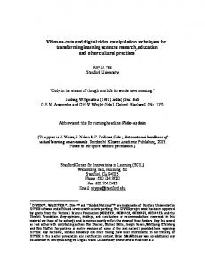
Fig. 15. Comparison between selective and non-selective coding of the head of the mother in frames number 0 ( rst row), 84 (second row) of the Mother and Daughter sequence. Left: original frames, Center: selective coding, Right: non-selective coding.
partition is projected and the projected partition can be seen in the center of the second row. This step de nes the time evolution of the previously transmitted regions. Based on the projected partition, the Partition Tree is created: in the example of Fig. 9, levels 1 and 2 are obtained by hierarchical segmentation following a spatial homogeneity criterion. Note in particular, how regions representing details of the face or of the background are introduced in the universe of regions. Levels 4 and 5 are created by merging regions with similar motion. Note here how background regions are merged because of their homogeneity in motion. The nal partition is shown in the center of the lower row. In this partition, some regions are homogeneous in terms of gray level (regions corresponding to homogeneous part of the building) and others are homogeneous in motion (region corresponding to the face). Finally, the original as well as the resulting coded frames are shown in the lower row. The algorithm has been mainly tested with QCIF and CIF sequences and bit rates from 24 to 320 Kbits/s. In order to demonstrate the capability of the algorithm to cope with various types of sequences and scenarios, two di�erent examples are presented in this section: � The example of Fig. 10 shows the frames of the sequence Foreman coded at 42 Kbits/s. This sequence is in QCIF format (176x144 pixels) and has been coded at 5 frames/s. The rst row corresponds to the original frames number 0, 115 and 235 and the second row to the coded frames. The time evolution of the PSNR and of the amount of bit per frame is shown in Fig. 11 and Fig. 12. The mean PSNR is around 30.5-31.0 dB and increases at the end of the sequence where the motion tends to disappear. In Fig. 12, together with the total number of bits per frame, the main pieces of information are shown: decision, motion, shape and texture/color. It can be seen in particular that the bit-stream increases around frame 180 which is a di�-
cult part of the sequence involving a strong panning. A signi cant part of the texture/color information cannot be compensated and has to be sent in intra mode. Moreover, a fairly high number of new regions are introduced in the partition. Finally, at the end of the sequence, the number of bits devoted to the shape information drops because the sequence become almost still and most regions are merged together. � In turn, the example of Fig. 13 shows the frames of the sequence Children coded at 320 Kbits/s. This sequence is in QCIF format and has been coded at 15 frames/s. The rst row corresponds to the original frames number 6, 100 and 192 and the second row to the coded frames. Details about the evolution of the PSNR and the number of bits per frame can be found in Fig. 14. Together with these results, we also show the time evolution of the Lagrange parameter � that de nes the rate-distortion ratio. The average (computed for the whole sequence) results of the bit allocation among the di�erent types of information for both examples are summarized in Table I. Note that the Decision algorithm has selected a quite di�erent strategy for the two bit rates: for low bit rates almost 20 % of the bit stream is devoted to the partition information whereas less than 10% is used for this type of information for higher bit rates. Finally, let us mention that by comparison with the algorithm presented in [32] using a much simpler bit allocation rule, the current algorithm provides between 2 and 3 dB of PSNR for very low bit rates (30-40 kBits). B. Content-based selective coding In order to address content-based functionalities, images have to be described in terms of objects or groups of objects. These objects can be de ned automatically or by the user, even on the receiver side in the case of an interactive application. Once they have been de ned, the algorithm should make possible their tracking, within the coding sc-
72
IEEE TRANSACTIONS ON CIRCUITS AND SYSTEMS FOR VIDEO TECHNOLOGY, VOL. 7, NO. 1, FEBRUARY 1997
heme, through the time domain. Such a possibility opens, for instance, the ability to encode objects of interest with a higher quality than other parts of the image. In the proposed algorithm, the object tracking is mainly related to the Projection and Partition Tree blocks, whereas the selective coding is associated to the Decision block. � Projection: The partition of the previous frame, which should already contain a region or set of regions describing the objects of interest, is projected following the double partition approach that has been presented in Section II.B. The position of the objects of interest in the current frame is obtained by regrouping the projection of the regions that formed the objects of interest in the previous frame. � Partition Tree: The set of partitions that forms the Partition Tree is created having in mind the constraint introduced by the projection of the objects of interest. The di�erent proposals of regions contained in the Partition Tree must not be in contradiction with the task of tracking the objects of interest. This translates into preventing, for partitions above the projected partition, the merging of regions with similar motion if they do not belong to the same object of interest. Such a merging would make impossible the separate tracking of the objects of interest. � Decision: This block should yield a coding strategy leading to a lower distortion within the objects of interest than in other areas of the image. In order to obtain this selective coding, the bit allocation strategy used in the basic coding algorithm is slightly modi ed. In this case, if a target bit rate has to be reached, selective coding can be implemented by simply multiplying by a given factor the distortion in the regions forming the objects of interest. � Coding: This block does not need to be changed since the coding techniques used in this functionality are the same as those used in the general case. Fig. 15 presents the results of applying the previous algorithm to the sequence Mother and Daughter. The rst column in Fig. 15 presents two original frames of the sequence, whereas the second and third columns show the decoded frames using selective and non-selective coding, respectively. The whole sequence has been coded in both cases at 30 Kbits/s and 5 frames/s. In this example, the head of the mother has been selected as area of interest to be tracked and selectively coded. The selective coding has been carried out by multiplying by a factor 10 the distortion inside this area of interest. The di�erent qualities obtained for the heads of both persons in the scene should be highlighted. In addition, note that the evolution of the mother's face is correctly tracked. IV. Conclusions
ning the coding strategy, it leads to the optimization of the partition as well as of the set of coding techniques to be used in each region. One of the advantages of the approach is that the basic scheme which has been developed to achieve compression can be easily modi ed to deal with a large set of contentbased functionalities. Moreover, the structure itself of the algorithm allows the integration and the comparison of new tools such as motion estimation, contour coding, texture coding, projection, etc. The computational complexity of the encoding process is largely dominated by the number of di�erent texture coding techniques that are proposed to the Decision. In the description of the algorithm, we have implicitly assumed that all techniques were tested for all regions. This is of course not necessary and, in practice, one can design rules to a priori know that it is useless to try one technique in a given region. The proposed algorithm can be improved in several directions. Beside improving each processing block, there are two particular points of interest. First, the distortion measure that has been used is the Squared Error because it is a simple additive criterion. However, it could be replaced by a more perceptually relevant criterion. Second, the optimization has been carried on a frame basis. Improvements can certainly be achieved if the optimization is done on a larger time scale. [1] [2] [3] [4] [5] [6]
[7] [8] [9]
This paper has presented and discussed a generic video coding algorithm. It is a region-based scheme where regions are tracked in time. The bit allocation plays a central [10] role in the coding process, it makes the link between the analysis and the synthesis parts of the encoder. While de-
References M. Barlaud, P. Sol�e, T. Gaidon, Antonini M., and P. Mathieu. Pyramidal lattice vector quantization for multiscale image coding. IEEE Transactions on Image Processing, 3(4):367{381, July 1994. H. J. Barnard. Image and video coding using a wavelet decomposition. PhD thesis, Delft University, 1994. J. Benois, L. Wu, and D. Barba. Joint contour-based and motion-based image sequences segmentation for TV image coding at low bit rate. In Visual Communication and Image Processing, pages 1074{1085, Chicago, USA, September 1994. P. Bouthemy and E. Fran�cois. Motion segmentation and qualitative dynamic scene analysis from an image sequence. International Journal of Computer Vision, 10(2):157{182, 1993. J. H. Conway and N. J. A. Sloane. Fast quantizing and decoding algorithms for lattice quantizers and codes. IEEE Transactions on Information Theory, 28(2):713{718, March 1982. LEP: I. Corset, L. Bouchard, S. Jeannin, UPC: P. Salembier, F. Marqu�es, M. Pard�as, R. Morros, CMM: F. Meyer, and B. Marcotegui. Segmentation-based coding system allowing the manipulation of objects (SESAME). Technical Report ISO/IECJTC1/SC29/WG11/MPEG95/408, LEP, UPC, CMM, November 1995. J. L. Dugelay and H. Sanson. Di�erential methods for the identi cation of 2D and 3D motion models in image sequences. Signal Processing, Image Communication, 7:105{127, 1995. M. Gilge, T. Engelhardt, and Mehlan R. Coding of arbitrarely shaped image segments based on a generalized orthogonal transform. EURASIP, Image Communications, 1(2):153{180, October 1989. C. Gu and M. Kunt. Very low bit-rate video coding using multicriterion segmentation. In First IEEE International Conference on Image Processing, volume II, pages 418{422, Texas, U.S.A., November 1994. E. Jensen, K. Rijkse, I. Lagendijk, and P. van Beek. Coding of arbitrarily shaped image segments. In Workshop on Image Analysis and Synthesis in Image Coding, Berlin, Germany, October 1994.
SALEMBIER ET AL.: SEGMENTATION-BASED VIDEO CODING SYSTEM ALLOWING THE MANIPULATION OF OBJECTS
[11] M. Kunt, A. Ikonomopoulos, and M. Kocher. Second generation image coding techniques. Proceedings of the IEEE, 73(4):549{ 575, April 1985. [12] F. Marqu�es. Motion stability in image sequence segmentation using the watershed algorithm. In P. Maragos, R.W. Schafer, and M.A. Butt, editors, Third workshop on Mathematical morphology and its applications to image processing, pages 321{328. Kluwer Academic Publishers, Atlanta, USA, May 1996. [13] F. Marqu�es, B. Marcotegui, and F. Meyer. Tracking areas of interest for content-based functionalities in segmentation-based video coding. In IEEE International Conference on Acoustics, Speech and Signal Processing, ICASSP'96, Atlanta, USA, May 1996. [14] F. Marqu�es, J. Sauleda, and A. Gasull. Shape and location coding for contour images. In Picture Coding Symposium, pages 18.6.1{18.6.2, Lausanne, Switzerland, March 1993. [15] F. Marqu�es, V. Vera, and A. Gasull. A hierarchical image sequence model for segmentation: Application to object-based sequence coding. In Proc. SPIE Visual Communication and Signal Processing-94 Conference, VCIP'94, pages 554{563, Chicago, USA, Oct 1994. [16] F. Meyer and S. Beucher. Morphological segmentation. Journal of Visual Communication and Image Representation, 1(1):21{ 46, September 1990. [17] R. Morros, F. Marqu�es, M. Pard�as, and P. Salembier. Video sequence segmentation based on rate-distortion theory. In SPIE Visual Communication and Image Processing, VCIP'96, volume 2727, pages 1185{1196, Orlando (FL), USA, March 1996. [18] MPEG. MPEG-4 Proposal Package Description (PPD). Technical Report ISO/IEC JTC1/SC29/WG11, MPEG, July 1995. [19] H.G. Musmann, M. H}otter, and J. Ostermann. Object-oriented analysis-synthesis coding of moving images. Signal Processing, Image Communication, 1(2):117{138, October 1989. [20] A. Ortega, K. Ramchandran, and M. Vetterli. Optimal bu�erconstrained source quantization and fast approximations. In Proc. IEEE Int. Symp. Circuits and Systems, volume 1, May 1992. [21] M. Pard�as and P. Salembier. Joint region and motion estimation with morphological tools. In J. Serra and P. Soille, editors, Second Workshop on Mathematical Morphology and its Applications to Signal Processing, pages 93{100, Fontainebleau, France, September 1994. Kluwer Academic Press. [22] M. Pard�as and P. Salembier. Time-recursive segmentation of image sequences. In Holt, Cowan, Grant, and Sandham, editors, EUSIPCO 94, VII European Signal Processing Conference, pages 18{21, Edinburgh, U.K., September 13-16 1994. [23] M. Pard�as, P. Salembier, and B. Gonz�alez. Motion and region overlapping estimation for segmentation-based video coding. In IEEE International Conference on Image Processing, ICIP'94, volume II, pages 428{432, Austin, Texas, November 1994. [24] M. Pard�as, P. Salembier, F. Marqu�es, and R. Morros. Partition tree for segmentation-based video coding. In IEEE International Conference on Acoustics, Speech & Signal Processing, ICASSP'96, volume IV, pages 1983{1986, Atlanta (GA), USA, May 1996. [25] K. Ramchandran and M. Vetterli. Best wavelet packet bases in a rate-distorsion sense. IEEE Transactions on Image Processing, 2(2):160{175, April 1993. [26] E. Reusens. Joint optimization of representation model and frame segmentation for generic video compression. EURASIP Signal Processing, 46(11):105{117, September 1995. [27] P. Salembier. Morphological multiscale segmentation for image coding. EURASIP Signal Processing, 38(3):359{386, September 1994. [28] P. Salembier. Motion compensated partition coding. In SPIE Visual Communication and Image Processing, VCIP'96, volume 2727, pages 403{415, Orlando, USA, March 1996. [29] P. Salembier, F. Marqu�es, and A. Gasull. Coding of partition sequences. In L. Torres and M. Kunt, editors, Video Coding: The Second Generation Approach. Kluwer, 1996. ISBN: 0 7923 9680 4. [30] P. Salembier and M. Pard�as. Hierarchical morphological segmentation for image sequence coding. IEEE Transactions on Image Processing, 3(5):639{651, September 1994. [31] P. Salembier and J. Serra. Flat zones ltering, connected operators and lters by reconstruction. IEEE Transactions on Image Processing, 3(8):1153{1160, August 1995.
73
[32] P. Salembier, L. Torres, F. Meyer, and C. Gu. Region-based video coding using mathematical morphology. Proceedings of IEEE (Invited paper), 83(6):843{857, June 1995. [33] H. Sanson. Toward a robust parametric identi cation of motion on regions of arbitrary shape by non-linear optimization. In Proceedings of IEEE Internatioanl Conference on Image Processing, ICIP'95, volume I, pages 203{206, October 1995. [34] Y. Shoham and A. Gersho. E�cient bit allocation for an arbitrary set of quantizers. IEEE Transactions on Acoustics, Speech, and Signal Processing, 36:1445{1453, September 1988. [35] T. Sikora, S. Bauer, and B. Makai. E�ciency of shape-adaptive 2-D transforms for coding of arbitrarily shaped image segments. IEEE Transactions on Circuits and Systems for Video Technology, 5(1):59{62, February 1995. [36] G. Tziritas and C. Labit. Motion analysis for image sequence coding, volume 4 of Advances in Image Communication. Elsevier, 1994. [37] P. Willemin, T. Reed, and M. Kunt. Image sequence coding by split and merge. IEEE Transactions on Communications, 39(12):1845{1855, December 1991.