The use of a Structural Health Monitoring System (SHMS) in order to evaluate the ... This kind of sensors are immune to electromagnetic interference, are.
Seismic Retrofitting and Structural Health Monitoring of a Masonry Vault by using GFRP Grids with Embedded FBG Sensors VINCENZO GATTULI, FRANCESCO POTENZA, JESSICA TOTI and FILIPPO VALVONA
ABSTRACT Fiber reinforced polymer (FRP) materials are currently used for strengthening of masonry structures. The behavior of this retrofit technique depends on the bond characteristics of the FRP to the external surface of the structure. A promising method to control the durability of the FRP reinforced structures is to incorporate fiber optical sensors (FOSs) in the composite material during its application or manufacture. The research leads to design of composite systems for the seismic retrofitting of an ancient masonry vault. The reinforcement technique involves the use of composite systems made up by FRP integrated with FOSs. The FOSs are employed as diagnostic tool for structural health monitoring. INTRODUCTION Preservation of the architectural heritage is considered a fundamental issue in the cultural life of modern societies. Modern requirements for a rehabilitation intervention include reversibility, unobtrusiveness, minimum repair and respect of the original construction, as well the obvious functional and structural requirements. Structural reinforcement using Fiber Reinforced Polymers (FRP) has gained much attention as strengthening technique in civil engineering structures. Indeed, the FRP strengthening offers several advantages over conventional one (steel, aluminum, etc.), such as high strength-to-weight, stiffness-to-weight ratios combined with a fast and easy application. For these reasons, the use of FRP in civil engineering is increasing especially for repairing and for seismic retrofit of existing structures or infrastructures. Many research activities [1] have demonstrated the effective of the FRP material as strengthening technique; however, as the application of FRP materials in civil engineering is quite recent, several questions regarding their long term behavior and durability remain still unresolved. A common cause of failure in FRP repaired members is abrupt debonding failures [2-3].
University of L’Aquila, Department of Civil Architectural and Environmental Engineering, via Giovanni Gronchi – Zona Industriale di Pile, 67100, L’Aquila.
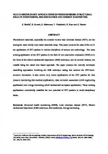
The use of a Structural Health Monitoring System (SHMS) in order to evaluate the durability of the FRP reinforced structures in real time and ensure its security becomes essential. An elegant and promising method to achieve this aim is to incorporate fiber optical sensors (FOSs) in the composite material during its application or manufacture. The FOSs devices allow for the complete check of strains and accordingly the detection of debonding phenomena. Several types of advanced sensing technologies based on fiber optical sensors (FOSs) have been developed for this purpose so far [45]. In particular, the FBG sensor, thanks to its localized high precision measurements, represents the most widely used technology among FOSs. In the present paper, an innovative seismic retrofitting technique for existing masonry structures is examined. In particular, a masonry polycentric pavilion vault damaged during 2009 L’Aquila earthquake is considered as case study. The vault, firstly repaired, is reinforced by arranging on extrados Glass Fiber Reinforced Polymers (GFRP) grids, glued onto the masonry support with the Hydraulic Lime Mortar (HLM). The HLM with respect to conventional bonding materials (epoxy or polyester resin) makes the strengthening technique more compatible with the masonry support in term of stiffness, strengths and thermal coefficient. Moreover, the GFRP reinforcement system is integrated with FBG sensors by gluing them at different points of the GFRP grid. The work is organized as follows: first, the working principle of the FBG sensor is provided; then, advanced numerical simulations are performed both in order to assess the effectiveness of GFRP strengthening in retrofitting the masonry vault and to support the design of the SHMS as strain measurement system. FBG SENSORS Structural integration of fiber-optic sensing systems represents a new branch of modern civil engineering. FOSs have a number of advantages over their electrical counterparts. This kind of sensors are immune to electromagnetic interference, are lightweight and have small physical dimensions, suitable for being embedded into or attached to a structure. Long-term strain measures are pivotal in avoiding unexpected failure or cracking and can be useful in evaluating design limits of the structures. FBG is a type of distributed Bragg reflector constructed in a short segment of optical fiber that reflects particular wavelengths of light and transmits all others. This is achieved by creating a periodic variation in the refractive index of the fiber core (Figure 1), which generates a wavelength-specific dielectric mirror. For mechanical protection the glass fiber gets an additional coat of synthetic material. Specifically, the reflected wavelength λΒ, called the Bragg wavelength, is defined by the following relationship: λB = 2η eff ∆
(1)
where ηeff is the effective refractive index of the grating in the fiber core and ∆ is the period of diffraction. This term of the light spectrum will be missing in the penetrated array. Changes in strain and temperature affect both the effective refractive index ηeff and grating period ∆ of an FBG, which results in a shift in the reflected wavelength.
Figure 1. Glass Fiber with Bragg Grating.
The change of wavelength of an FBG due to strain and temperature can be approximately described by equation (2):
∆λB
λB
= (1 − pe )∆ε + (α + ξ ) ∆T
(2)
where ∆λΒ is the wavelength shift. The first expression describes the impact of strain on the wavelength shift, where pe is the strain-optic coefficient, and ∆ε is the change of strain experienced by the grating. The second expression describes the impact of temperature on the wavelength shift, where ξ is thermo-optic coefficient, α is thermo-elastic coefficient and ∆Τ is the temperature variation. As the FBG responds to both strain and temperature, it needs to account for both effects and distinguish between the two. For sensing temperature, the FBG must remain mechanically unstrained. It uses packaged FBG temperature sensors to ensure the FBG inside the package is not coupled to any bending, tension, compression, or torsion forces. Instead, the FBG strain sensors are generally complex because both temperature and strain influence the sensor’s reflected wavelength. For proper strain measurements, it must compensate for the temperature effects on the FBG. For example, it can achieve this by installing an FBG temperature sensor in close thermal contact with the FBG strain sensor. A simple subtraction of the FBG temperature sensor wavelength shift from the FBG strain sensor wavelength shift removes the second expression of equation (2), yielding a temperature compensated strain value. Finally, FBG can measure strain or temperature changes only at one point, but there is the possibility to distribute several Bragg gratings in one optical fiber. DESIGN OF THE GFRP STRENGTHENING FOR A MASONRY VAULT
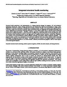
Finite element analyses are carried out in order to examine the mechanical behavior of a masonry vault strengthened by Glass Fiber Reinforced Polymers (GFRP). (a)
(b) Figure 2. Masonry vault during retrofitting works: (a) bare vault; (b) GRFP grids.
(b)
(a)
(c)
Figure 3. Geometry of the vault: plan (a), transversal (b) and longitudinal (c) polycentric arches.
The simulations of the unreinforced and reinforced masonry vault, performed by the use of MIDAS code are developed to study the efficacy of the GFRP strengthening and, at same time, to support the design of the SHMS embedded in the structural reinforce. Case study: geometry and mechanical properties
A masonry vault, belonging to an old building located at the historical centre of L’Aquila and strongly damaged during 2009 earthquake, is considered as case study. The vault, firstly repaired, is reinforced by arranging on extrados GFRP grids, fixed at the masonry support with HLM. Moreover, the GFRP reinforcement system is integrated with FBG sensors by gluing them at different points of the GFRP grid. Some photos of the masonry vault, taken during the rehabilitation phases, are reported in Figure 2. A field survey of the structure allows defining the typology and the geometry of the masonry vault. Specifically, as schematically showed in Figure 3, the examined vault is a polycentric pavilion on a square plan; made by clay brick with dimensions of 4 ×10 × 25 cm3. It was not possible to take masonry samples for direct evaluation of the mechanical parameters. For this reason, the Italian building code (Instruction Document of Feb. 2nd 2009, n. 617) is taken as reference in order to define the mechanical properties of the masonry. Indeed, the code suggests, in absence of a surveys campaign, some values for masonry mechanical parameters. Furthermore, since these are precautionary values characterizing poor quality masonries, the aforementioned code offers correction factors in the case of better conditions as good mortar, limited thickness of joints and so on. Finally, the estimated mechanical parameters are presented in Table I. In this table fm is the mean compressive strength, E is the Young modulus, G is the shear modulus and W is the density. The applied GFRP sheet has an average thickness of 0.95 mm and grid mesh with dimensions of 28 × 28 mm2. The GFRP reinforcement is bounded on the top surface of the masonry vault including it in a HLM jet of 1 cm of thickness. The mechanical properties of the GFRP and the HLM are inserted in Table II, where fc, ft and a indicate the compressive strength, tensile strength and the adhesion force, respectively. TABLE I. MECHANICAL PARAMETERS OF THE MASONRY W E ν fm (MPa) (kN/m3) (MPa) 3375 0.15 5.4 18
TABLE II. MECHANICAL PARAMETERS OF THE GFRP AND HLM E ν fc ft a (MPa) (MPa) (MPa) (MPa) 133430 0.268 GFRP 9000 0.1 15 5 0.8 HLM
FE model
The pavilion masonry vault is modelled by using Mindlin-Reissner shell elements. The shear deformations are taken into account according to a linear shear wharping function. In the finite element discretization, four nodes shell elements are employed. At integration point level, in order to reproduce the mechanical response of the masonry, two nonlinear constitutive laws are adopted: STRUctural MASonry (STRUMAS) model and Total Strain Crack model (TSC). In particular, the STRUMAS model and TSC model are based on different scale approaches. In detail, the STRUMAS model, mainly developed for the study of masonry structures, is based on micro-macro scale approach, where microscopic and macroscopic scales are intrinsically coupled. At the micro level, all the constituents of the masonry (i.e. brick, bed and head mortar joints) are modelled in detail, taking into account their geometrical arrangement, size and specific nonlinear constitutive laws. At the macrolevel, a homogenization technique is developed to identify an equivalent orthotropic continuum model. In particular, an elasto-plastic behavior in tension and a linear elastic behavior in compression with infinite strength are considered for the all constituents of the masonry. Instead, the TSC model classified as band smeared crack model is based on macro-scale approach, i.e. considering the masonry an homogenized medium, without distinguishing the brick and the mortar phase. It can be further classified as the fixed crack model and the rotating crack model depending on the reference crack axes. The materials exhibit isotropic properties prior to cracking and anisotropic properties after cracking. In MIDAS code the properties of concrete are treated as orthotropic materials after cracking. Specifically, the rotating crack assumption available the software is used; the compression behavior of the masonry is modeled by a parabolic softening function; while the tension one is modelled by exponential softening function. In the numerical model of the strengthened masonry vault, the presence of the GFRP reinforcement is taken into account by adding on the extrados of the vault four node membrane elements in plane stress state hypothesis. The adhesion of the GFRP reinforcement to the masonry support, realized through the application of the hydraulic lime, is modelled by inserting eight node interface elements. About the interface constitute law, in order to consider the possible force resisting the GRP reinforcement-masonry vault sliding, a friction Coulomb model is adopted. Numerical results
The nonlinear response and the damage state occurring in both the bare masonry vault and GFRP masonry vault for a specific loading condition are examined. Specifically, the efficiency of the GFRP reinforcement is checked considering, in addition to the self-weight, an incremental uniformly distributed vertical load q.
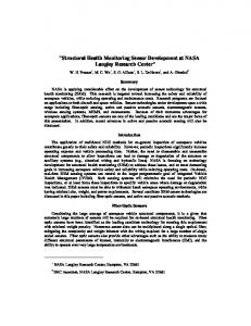
Figure 4(a) shows the mechanical response of the bare masonry vault for the first load case obtained adopting the two modeling approaches, in term of applied load q versus the vertical displacement of the node located at vault key, vA. It appears evident from this figure that the two material model provides the same estimation of the loadbearing capacity. The peak load computed with the two constitutive laws is around the value of 5 kN/m2. As expected, the substantial difference between the two models is revealed in the prediction of the structural ductility. Indeed, the TSC model, at least from qualitative point of view, than the STRUMAS model provides a more reasonable trend of the post peak behavior of the masonry structure, typically characterized by a very abrupt softening branch. Figure 4(b) shows the comparison of response between the unreinforced and reinforced vault. From the results obtained by the simulation, it appears evident that the presence of GFRP grids leads an increase of the bearing capacity and structural ductility. In particular, the peak load value for the reinforced vault is 25.2 kN/m2, which is about 5 times higher than the one computed without the GFRP grids, while the displacement at which the maximum load is reached for the reinforced vault is about 7 time higher than the one evaluated for the unreinforced vault. The principal stress state and the cracking status in the unreinforced vault and reinforced vault are illustrated in Figure 5 and Figure 6, respectively. Specifically, the stress maps are reported for q= 5 kN/m2 , while the crack patterns are shown at the end of the softening response when the collapse mechanism of the structure is reached. By observing Figure 5, it can be possible to note that the crack status in the bare masonry vault is due to the achievement of the tensile limit strength (about fc/14) and, as consequence, the tensile cracks propagate in parallel to the direction of the compression stresses. The developed collapse mechanism of the unreinforced vault is characterized by the coalescence of open cracks between two opposite corner zones at the intrados and by the coalescence of horizontal and corner open cracks at the extrados. 6 25 5
2
q [kN/m ]
2
q [kN/m ]
20
4 3
2
STRUMAS model TSC model
1
0 0
5
10
vA [mm]
15
Unreinfoced vault Reinforced vault
15 10 5 0 0
20
40
60
80
vA [mm]
(a) (b) Figure 4. Mechanical response of the vault: (a) comparison between STRUMAS and TSC model for unreinforced vault; (b) comparison between the unreinforced and reinforced vault by adopting the TSC model.
(a)
(d)
(b)
(e)
(c)
(f)
Figure 5. (a) Maximum principal stress, (b) minimum principal stress, (c) cracking at the top of the vault; (d) Maximum principal stress; (e) minimum principal stress (f) cracking at the bottom of the vault.
With reference to Figure 5 and 6, it can be hightailed that the stress state values in the reinforced vault appears lower than the ones computed for the unreinforced structure; the damaged zones approximately localized for the two cases in the same regions. As usual in experimental works and, in particular, in structural monitoring ones, the first issue to be faced is setting up of the sensors placement on the structure relatively to the entities to control. To this purpose, the numerical model is very useful to predict structural zones where stresses and strains need to be monitored. For the examined vault study, a quite complex comparison of deformed shapes strains for self-weight, longitudinal and transversal seismic loads has to be made. For example, according to the proposed loading condition, the optimal position of the sensors on the extrados of the pavilion vault should be located in correspondence of that zones, where fully open cracks occur (Figure 5c and Figure 6b). CONCLUSIONS
The research activity focused on the development of an innovative seismic retrofitting intervention for the masonry structure. In particular, the strengthening technique is realized with GFRP sheets, which are externally bounded to the
masonry surface through HLM. The HLM makes the reinforce system more compatible with the masonry support in term of stiffness, strengths and thermal coefficient. Furthermore, FBG sensors are employed as SHMS for strain measurements. Indeed, embedded at the HLM-GFRP interface, they are able to control the correct function of the GFRP strengthening and detect possible masonry damage or detachment phenomena. The authors present some preliminary studies useful to the design of the monitoring and retrofit system for an old masonry pavilion vault. Numerical simulations demonstrate the efficacy of the strengthening technique and suggest the optimal positions of the FBG sensors in the GFRP layer. Experimental investigations and dynamic testing [6] will be conduct to test the real action and the reliability of the FBG sensors for the long-term monitoring of the examined masonry structure. (a)
(c)
(b)
(d)
Figure 6. (a) Maximum principal stress, (b) cracking at the top of the vault; (c) Maximum principal stress and cracking (d) at the bottom of the reinforced vault.
REFERENCES 1.
2. 3. 4.
5.
6.
Bakis, C., Bank, L., Brown, V., Cosenza, E., Davalos, J., Lesko, J., Machida, A., Rizkalla, S., and Triantafillou, T. 2002. ”Fiber-Reinforced Polymer Composites for Construction—State-of-the-Art Review.” J. Compos. Constr., 6(2), 73–87. E. Sacco, J. Toti. 2010. “Interface elements for the analysis of masonry structures”, Int. J. Comput. Methods Engrg. Sci. Mech., 11, 354–373. S. Marfia, E. Sacco, J. Toti. 2012. “A coupled nonlocal interface damage model for FRP strengthening detachment”, Comput. Mech., 50 (3), 335–351. Y. Wang, Q. Hao and J. Ou. 2009. “Experimental testing of a self-sensing FRP-concrete composite beam using FBG sensors”, in Proceedings of Sensors and Smart Structures Technologies for Civil, Mechanical and Aerospace Systems, SPIE, 7292, 72923T-1. F. Bastianini, M. Corradi, A. Borri and A. Di Tommasi. 2005. “Retrofit and monitoring of an historical building using “Smart” CFRP with embedded fibre optic Brillouin sensors”, Construction and Building Materials, 19, 525-535. D. Foti, V. Gattulli and F. Potenza. 2014. “Output-only identification and model updating by dynamic testing in unfavorable conditions of a seismically damaged building”. Computer-Aided Civil and Infrastructure Engineering, 29, 659-675.