Adeel Ahmed, Ashfaq khan, Naeem Khattak, Zuhaib Ali Khan,. Waheed Gul, Naveed Ahmad, Zeshan Zahir,. PG Student, Department of Mechanical Engineering ...
ISSN: 2350-0328 International Journal of Advanced Research in Science, Engineering and Technology Vol. 2, Issue 6 , June 2015
Selection of Cutting Parameters for Minimizing the Real Time Current Drawn during Single Pass Turning Operations using Response Surface Methodology Adeel Ahmed, Ashfaq khan, Naeem Khattak, Zuhaib Ali Khan, Waheed Gul, Naveed Ahmad, Zeshan Zahir, PG Student, Department of Mechanical Engineering, University of Engineering and Technology Peshawar, Pakistan Assistant Prof., Department of Mechanical Engineering, University of Engineering and Technology Peshawar, Pakistan Professor, Department of Mechanical Engineering, University of Engineering and Technology Peshawar, Pakistan Lecturer, Department of Mechanical Engineering, University of Engineering and Technology Peshawar, Pakistan Lecturer, Department of Mechanical Engineering, Cecos University of IT and Emerging Sciences Peshawar, Pakistan Lecturer, Department of Mechanical Engineering, University of Engineering and Technology Peshawar, Pakistan Lecturer, Department of Mechanical Engineering, University of Engineering and Technology Peshawar, Pakistan
ABSTRACT: The objective of this research is to develop a strategy that will be helpful in selection of cutting parameters during single pass turning operation for reducing the real time current drawn from the grid. As current is directly related to the energy been used during machining so minimizing energy will automatically reduce the current been drawn from the grid. The important cutting parameters that can be varied during machining are Cutting Speed, Feed Rate and Depth of Cut. Two different approaches can be used for selection of cutting parameters for reducing the real time current drawn. The first approach that can be used is to minimize the real time current drawn by considering the problem as un-constrained and the second approach is that to optimize the problem by considering the problem as constrained by tool life of the indexable insert used for turning. In this research the first approach is used. An equation has been developed to find the energy consumed during single pass turning operation which include the terms for idling energy and term for cutting energy. For solution of the problem Statistical Analysis has been performed using Design Expert software and a regression model for energy used during cutting has been obtained. The final equation obtained has been programmed in MATLAB to perform the iterative procedure by using nested loops with a suitable step size. The results obtained have been arranged in ascending order to find the minimum energy points at the top. The minimum energy obtained for this problem was at cutting speed equal to 250 m/min, feed rate equal to 0.2 mm/rev and depth of cut equal to 0.5 mm. KEYWORDS: Single pass turning operations, Minimum Energy, Statistical Analysis. I. INTRODUCTION Energy crisis is increasing day by day because with the advancements in technology the energy consumption increases from individual utility to the huge industries that rely on the energy to even a higher extent. Manufacturing industry is huge energy consuming sector which draws energy for manufacturing ranging from a small component to the manufacturing of large assemblies. Machining is a widely used manufacturing process which shapes the product by material removal technique. Machining, like other manufacturing processes, consumes a lot of energy, so optimizing the process for minimum energy is extremely important. Turning operations are a special class of mechanical machining process in which the work piece rotates with a particular speed and the cutting tool is given a proper feed rate and depth of cut to remove the material [1].
Copyright to IJARSET
www.ijarset.com
707
ISSN: 2350-0328 International Journal of Advanced Research in Science, Engineering and Technology Vol. 2, Issue 6 , June 2015
Significant research has been conducted on optimizing cutting parameters based on reducing the cost of the machined products or decreasing the production time. As an example Chen et al [2] explained the methodology for optimizing the cutting parameters for reducing the cost of machined product in turning operation. Similarly Hinduja and Sandiford [3] presented the model for reducing the cost of machined product in milling process by optimizing the cutting parameters. Chapman [4] suggested that energy usage can be can be optimized by studying in detail the individual process. This research activity is dedicated to the optimization of cutting conditions based on criteria of minimum energy consumption by using Response Surface Methodology. Noorul and Jeyapaul [5] used taguchi technique in order to increase the efficiency of more than one response in drilling Al / SiC composite. After that Mohan et al. [6] utilized design of experiment technique and ANOVA to enhance the efficiency in surface roughness of drilling Glass fiber polyester. Palanikumar [7] used response surface methodology to enhance the efficiency of the processes for reducing the surface roughness of work piece with PCD tools while machining Al / SiC composite. Tosum and Ozler [8] used the Taguchi technique to perform the optimization of more than one characteristics in hot turning operations. Contour plot technique was utilized by Taramen to optimize the tool wear and forces that occur on the tool during finished turning operations [9]. Hamdan A. et al., carried out experiments to optimize the cutting conditions while machining of stainless steel to a cheive a better surface finish [10]. M. Kaladhar et. al., conducted experiments for the optimization of Material removal rate and surface finish of AISI 304 [11]. Khidhir and Mohamed focused on the influences of the cutting conditions on tool life in machining nickel based hastelloy-276 [12]. Selveraj and Chandermohan research was inclined towards the application of Taguchi’s technique to the optimization of cutting parameters for surface roughness of AISI 34 austenitic steel while turning in the dry environment [13]. Singh et. al., figured out the effects of cutting parameters on the material removal rate and surface roughness of EN-8 steel [14]. II. RELATED WORK Limited amount of work has been published that relates to the energy issues during machining as an example that of Dahmus and Gutowski [15]. Gutowski et al. stated that the fraction of energy consumed for actual machining may be a small portion of the total energy consumed when the total energy of machine tool is also taken into account [16]. This was also found they the primary energy that is used in raw materials is quite enormous as compared to final shaping processes [17]. The electrical power requirement for machining process can be calculated from the equation 2.1 found from the work of Gutowski [16].
P Po KV Where P is the instantaneous power requirement for machining in watts, Po is the idling power requirement of the machine tool in watts, K is the specific energy requirement for the turning operation in cubic millimetre per watt second and V is the volume removed per unit time in millimetre cube per second. Specific energies for different materials can be found from literature published by Kalpakjian & Schmid [18]. But these values though the name dictates that they are specific but they are not constant for a material because they depend on the cutting parameter cutting tool. While turning a work piece energy is consumed in the form of current been drawn from grid. During machining two types of energies in the form of current drawn include idling energy and energy used for cutting. The cutting energy itself is comprised of two energies, one that is related to the material removal and the other belongs to machine tool which is consuming energy during the time it is cutting material. The energy required for removal of unit material is called as specific cutting energy. Though this energy is specific but research shows that this energy remains specific if carried out with cutting speed more than certain limit. Cutting with different grades of tool insert and geometries will affect the energy requirement for removing same amount of material. As mentioned earlier that decent attention has been paid to the optimization of cutting parameter based on the criteria of reduced cost, reduced production time, reducing surface roughness, increasing tool life and decreasing tool wear but energy side still needs to be addressed. This research aims at optimizing the cutting parameters for reducing the energy footprints of the turned machined products by using the Response Surface Methodology. Literature also figure out that Design of Experiment, Response Surface Methodology and Taguchi techniques have been extensively used for optimization of cutting parameters in machining operations for reducing production time and cost while improving machining quality.
Copyright to IJARSET
www.ijarset.com
708
ISSN: 2350-0328 International Journal of Advanced Research in Science, Engineering and Technology Vol. 2, Issue 6 , June 2015
III. MATERIALS AND EQUIPMENTS The work piece (length 200 mm, diameter 75 mm) used for carrying out experiment was 1045. The machining was conducted using Carbide inserts KC - 5010 from KENNA METAL having a nose radius of 0.4 mm. Allowed cutting conditions for these inserts are listed in table 1. Table 1: Allowed cutting condition for the insert Cutting parameter
Max. allowed
Min. allowed
Cutting Speed
150 m/min
250 m/min
Feed Rate
0.10 mm/rev
0.20 mm/rev
Depth of Cut
0.5 mm
1.5 mm
The turning machine tool used for experimentation was Doosan Lynx 220L (rpm 20-3000, 25 Hp). To gather the data regarding the energy consumption a digital clamp-meter (SOGO JPN 26B) was used to measure the real time current drawn by the equipment. IV.RESEARCH METHODOLGY An equation needs to be developed which can be used to calculate the energy used in a single pass turning operation. Two different mathematical relations are required that is a relation for calculating idling energy consumption and energy during cutting. Once the equation has been developed experiments can be conducted. For the specific scenario that is the work material and cutting tool insert recommended cutting range should be evaluated to satisfy the tool breakage constraint. An experimental layout should be set with the help of Design Expert Software by using Response Surface Methodology technique in the whole recommended cutting range. Experiments are then supposed to be conducted at all design points obtained from design expert software. As a result of above experiments the parameters that are going to be found are machine setup time, current during idling of machine, current dawn during cutting. The corresponding values of Cutting Energy should be fed back to Design expert software. Model will be Analysed, ANOVA will be evaluated, diagnostic plots and lack of fit test for the model will be obtained from design expert software. If the Model fits well, Regression equation will be obtained. If not then some model fitting technique such as output transformation will be applied for proper fit of the model. Confirmation Experiments need to be conducted to check further the validity of the model obtained. Now if the Model is valid then the Cutting Energy term in the total Energy equation obtained should be replaced with their Regression Models. The total energy equation obtained will be programmed in MATLAB to perform iterative procedure to find out energies output for all possible combination of cutting parameters. All the results obtained will be arranged in ascending order. All points which violate the power constraint of the machine tool will be eliminated. The remaining result then shows all feasible points in ascending order from minimum energy perspective. V.ANALYTICAL MODEL From the perspective of energy utilized form grid by drawing current, the total energy can be divided into two groups i.e. Energy used during idling and energy used during cutting. While cutting the material the machine is still using the idling energy but put extra load on the grid when the cutting tool is engaged. These two terms will be separately called as machine tool energy during cutting and actual cutting energy. The total energy used will be the sum of energy used during idling and energy used during cutting. Energy used during cutting is the sum of the idling power and machining time product and cutting energy requirement for material. Mathematically
Et E1 E2 Where Et is the Total energy
E1 P1.t1 Where E1 is the energy used during idling, P1 is the instantaneous power requirement and t1 is the machine setup time required which will be found experimentally. P1 can be measured by measuring by current drawn during idling and multiplying it with the voltage. So Copyright to IJARSET
www.ijarset.com
709
ISSN: 2350-0328 International Journal of Advanced Research in Science, Engineering and Technology Vol. 2, Issue 6 , June 2015
E1 3.I1 .V .t1 Similarly
E2 P2 . t 2 Where E2 is the energy used during machining, P2 is the instantaneous power requirement and t2 is the machining time required. Finally E2 will be equal to 3.I 2 .V .t 2 where I2 is the current drawn during machining. Now as mentioned earlier, this energy can be further written as the sum of two parts, so mathematically
E2 Pot2 Pt c 2 Where Pc is the power that will be required if only power required is for cutting and the different modules of machine are not drawing the current. The term Pct2 represents actual cutting energy and as mentioned earlier the specific cutting energy requirement can change and hence for this part a regression model will be fitted from experimental data so as to predict this part of energy for different combination of cutting parameters. From experimental data this part of energy can be found from the equation as follows;
Pc t2 E2 Pot2 Machining time can be found with the help of equation below [1];
.D.L t2 Vc . f Where D,L,Vc and f are Diameter, Length, Cutting Speed and feed rate respectively. Incorporating the regression model in the E2 equation will yield
dl E2 Po Re gressionModelCuttingEnergy Vc f Final expression for Et will be
.d .l Et 3.I1.V t1 RegressionModelCuttingEnergy Vc . f VI. EXPERIMENTATION To avoid performing all the experiments for all combination of cutting parameters, experimental plan will be obtained from Design Expert software using Response surface Methodology. A total of 30 experiments were performed and the current drawn in all cases was measured. Machine setup time was measured as 3 minutes and idling current was measured as 4.5 Amperes. The rest of the results are shown in table below.
Run Order 1 2 3 4 5 6 7 8 9 10 11
Cutting Speed (m/min) A1 A2 A1 A3 A3 A3 A3 A2 A1 A2 A2
Copyright to IJARSET
Feed Rate (mm/rev) B3 B3 B2 B1 B3 B1 B1 B2 B1 B1 B2
Depth of Cut (mm) C1 C2 C2 C1 C1 C3 C3 C3 C3 C2 C3
www.ijarset.com
Current (Amperes) 5.9 8.3 6.6 5.7 6.9 8.0 8.0 8.7 6.6 6.4 8.8
710
ISSN: 2350-0328 International Journal of Advanced Research in Science, Engineering and Technology Vol. 2, Issue 6 , June 2015
12 13 14 15 16 17 18 19 20 21 22 23 24 25 26 27 28 29 30
A3 A2 A1 A1 A3 A2 A2 A2 A3 A3 A2 A1 A3 A1 A1 A1 A1 A2 A3
A= Cutting Speed B= Feed Rate C= Depth of Cut
B3 B2 B2 B3 B3 B2 B3 B1 B1 B3 B2 B3 B2 B1 B1 B1 B3 B2 B2
C3 C1 C2 C3 C1 C2 C2 C2 C1 C3 C2 C1 C2 C1 C1 C3 C3 C1 C2
11.5 5.9 6.4 8.7 6.8 7.3 8.4 6.6 5.6 11.6 7.4 5.9 8.0 5.2 5.2 6.7 8.7 5.9 7.9
A1, A2, A3 equals 150, 200 and 250 m/min respectively B1, B2, B3 equals 0.1, 0.15, 0.2 mm/rev respectively C1, C2, C3 equals 0.5, 1, 1.5 mm respectively VII. STATISTICAL ANALYSIS
A lot of situations in real world where the underlying physics of problem is either complicated or unknown and are solved using statistical analysis. Instead of having the actual model describing the behaviour of an output in response to the input parameters, an approximate model is obtained which is according to the observed data during experimentation. Response surface methodology is a good tool for obtaining the Response Surface in response to the varying input parameters. Regression models are obtained which can predict the response in those areas where experiments are not even performed. Central Composite design is used. The Regression model obtained for the cutting energy is given below. The output is transformed for better fit of the data.
1 3.8133*10 6 4.1478*106 D 1.3841*106 D2 CuttingEnergy ANOVA table for the cutting energy is given below. The insignificant terms have already been eliminated. ANOVA table clearly shows the effect of depth of cut on cutting energy requirement for different mount of material to be removed. As all the experiments were conducted either close or exceeding the cutting speed of 3 meters per second so the effect of cutting speed was insignificant and has been hence dropped from ANOVA table.
Copyright to IJARSET
www.ijarset.com
711
ISSN: 2350-0328 International Journal of Advanced Research in Science, Engineering and Technology Vol. 2, Issue 6 , June 2015
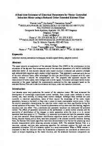
Response surface for the actual cutting energy is given below for varying cutting speed and feed rate and a constant depth of cut equal to 1 mm.
VIII. ITERATIVE PROCEDURE USING MATLAB The equation for the total energy has been programmed in MATLAB to perform the iterative procedure in the whole recommended cutting range by running the nested loops for the three variables that are cutting speed, feed rate and depth of cut. Step size of 10, 0.01 and 0.1 was chosen for cutting speed, feed rate and depth of cut respectively. The results are placed in ascending order to find the minimum energy points. All the points have been tested for the power constraint by comparing the available power at the spindle, to the power required for the machining. Based on this, any ratio less than unity was chosen as criterion for indication of constraint being violated. IX.RESULTS AND DISCUSSIONS The idling energy of a machine which is used in the form of machine setup time is a huge contributor in single pass turning operations. This energy is fixed and has nothing to do with cutting parameters and varying cutting parameters will not affect this part of energy. To reduce this energy the two possibilities are to either design machine tools that can be set easily or to design machine tools having low idling power requirements. The Response surface of the actual cutting energy shows that energy requirement for a specific amount of material to be removed is approximately same as for as the work piece materials and other problem variables remain constant. Copyright to IJARSET
www.ijarset.com
712
ISSN: 2350-0328 International Journal of Advanced Research in Science, Engineering and Technology Vol. 2, Issue 6 , June 2015
ANOVA table for cutting energy shows the effect of depth of cut on the cutting energy requirement and shows the effect of cutting speed and feed rate as insignificant. Though they are important contributors to instantaneous power requirement but for the cutting energy requirement these term cancels out when multiplied with the machining time. This result is in complete agreement with the theoretical model involving the concept of specific energy for the calculation of cutting energy requirement. Besides this the specific energy remains almost constant after a cutting speed of 3 m/s and as all the above experiments are conducted either exceeding or are close to cutting speed equal to 3 m/s. So from all these perspectives the fitted surface seems to be in agreement with the theory. If the machine tools with low setup time are designed they will only reduce the machine setup time but if the machine tools with low idling power are designed they will also reduce the machine tool energy used during cutting and hence the cutting energy part of the total energy. X.CONCLUSION Based on the method proposed in this research the final results showed that the minimum energy point was obtained at a cutting speed equal to 250 m/min, feed rate 0.2 mm/rev and depth of cut equal to 0.5 mm.
REFERENCES [1] [2] [3] [4] [5] [6] [7] [8] [9] [10] [11] [12] [13] [14] [15] [16] [17] [18] [19] [20] [21]
Mikkell P. Groover, Fundamental of modern manufacturing. ISBN-13: 978-0471744856 Chen SJ. Hinduja S. Barrow G, Automatic tool selection for rough turning operations. International journal of Machine Tools and Manufacture, 1989. 29: p. 535-553. Hinduja S. Sandiford D, An optimum two tool solution for milling 2 1/2D Features from technological and Geometric Viewpoints. CIRP Annals Manufacturing Technology, 2004. 53(1): p. 77-80. Chapman PF, Energy Costs: A review of Methods. Energy Policy, 1974. 2(2): p. 91-103. Noorul H.A. Marimuthu P. and Jeyapaul R., Multi response optimization of machining parameters of drilling Al/Sic metal Matrix composite using grey relational analysis in the Taguchi Mathod. International journal of Advance Manufacturing Technology, 2007: p. 250-255. Mohan S. Venugopal A. Rajadurai and Mannan S.L., Optimization of the Machinability of Al-SiC Metal Matrix Composite Using Dynamic Material Model. International journal of Materials and Metalurgical Transaction, 2008. 39: p. 2931-2940. Palanikumar K. Shanmugam K. Paulo D.J., Analysis and optimization of cutting parameters for surface roughness in machining Al/SiC particulate composites by PCD International journal of Materials and product Technology, 2010. 37: p. 117-128. Tosun N. and Ozler L., Optimization for hot turning operations with multiple performance characteristics. International journal of Advance Manufacturing Technology, 2004. 23: p. 777-782. K. Taramen, Multi-machining output Multi- Independant variable turning research by response surface methodology. International Journal of Production Research, 1974. 12(2): p. 233-245. Hmadan A. Sarhan Ahmed A.D. and Hamdi M.A., Optimization method of the machining parameters in high speed machining of stainless steel using coated carbide tool for the best surface finish. International journal of Advance Manufacturing Technology, 2012. 58: p. 81-91. Kaladhar M. Subbaiah K.V. and Rao Ch. S., Parametric optimization during machining of AISI 304 Austenitic steel using CVD coated DURATOMICTM cutting Insert. International Journal of Industrial engineering Computations, 2012. 3: p. 577-586. Khidhir B.A. and Mohamed B., Analyzing the effect of cutting parameters on surface roughness and tool wear when machining nickel based hastelloy-276. IOP Conference Series: Materials Science and Engineering, 2011. 17: p. 1-10. Selveraj D.P. and Chandermohan P., Optimization of surface roughness of AISI 304 austenitic stainless steel in dry turning operation using Taguchi Method. Journal of Engineering Science and Technology, 2010. 5(3): p. 293-301. Singh H. Khanna R. and Garg M.P., Effect of cutting parameters on MRR and Surface Roughness in turning EN-8 steel. International Journal of Current Engineering and Technology, 2011. 1(1): p. 100-104. Dahmus J. Gotowski T, An environmental Analysis of Machining. ASME International Mechanical Engineering Congress (IMECE) and R&D Expo, Anaheim, California, 2004: p. 1-10. Gutowski T. Dahmus J. and Thiri ez A, Electrical energy requirements for manufacturing processes. 13th CIRP International Conference on Life Cycle Engineering, Leuven, Belgium,, 2006. 623-27 Gutowski T, Design and manufacturing for the environment Springer-Verlag, 2007. Kalpakjian S and Schmid SR, Manuf acturing Engineering and Technology, Pearson Prentice Hall., 2006. 5. Dieter, G.E., Mechanical metallurgy, 1988, SI metric edition, McGraw-Hill, ISBN 0-07-100406-8. Edwards, L. and Endean, M., Manufacturing with materials, 1990, Butterworth Heinemann, ISBN 0-7506-2754-9. Beddroes, J. Bibbly M.J., Principles of metal manufacturing processes, Arnold, ISBN 0 340 731621.
Copyright to IJARSET
www.ijarset.com
713