Self-Repairing Systems Modeling and Verification using AGG Antonio Bucchiarone FBK-IRST, Trento, Italy via Sommarive 18, 38050 Trento, Italy
[email protected]
Patrizio Pelliccione, Charlie Vattani Dipartimento di Informatica Universit`a dell’Aquila L’Aquila, Italy
[email protected]
Abstract Self-Repairing (or healing) systems are systems equipped with a mechanism that monitors the system behaviour to determine whether it behaves within prefixed parameters. If a deviation exists, then the system itself is in charge of adapting its configuration. In this paper we show how to model self-repairing systems by means of Dynamic Software Architecture (DSA). DSAs are formalized as Typed (hyper)Graph Grammars (TGGs) and they are modeled and verified by using the AGG tool. The overall approach is applied to a traffic light system case study.
1. Introduction Traditional systems are usually designed with a set of requirements and a precise context that provides all the resources necessary to run system services in mind. On the contrary, the intended lifespan of modern software systems makes requirements and context evolution the norm rather than the exception. When the requirements and the context evolve, a software system must be able to face changes in an effective way with minimal human intervention otherwise it will soon become obsolete. Software systems must be designed with run-time evolution in mind and, at the same time, solutions must be adopted to keep the (user’s perceived as well as system intrinsic) dependability at a satisfactory level [1]. Mechanisms for run-time evolution are needed to provide good reactions to (system and context) changes. Dynamic Software architecture (DSA) [2], [3], [4], [5] plays a central role in enabling system evolution: it has to support models at run-time, continuous verification and self-repairing by providing a suitable infrastructure. When the changes are initiated and accessed internally, DSAs keep the name of Self-repairing DSAs [6]. Different approaches for self-repairing Dynamic Software Architecture have been proposed in literature, e.g., [6], [7]. Typically, they are bound to particular languages and models. In this paper we are aimed at understanding the main notions of DSAs by abstracting away from particular languages and notions. In other words, we want to give a uniform and formal representation of DSAs that is abstract enough to cover most
Olga Runge Department of Software Engineering and Theoretical Computer Science Technical University of Berlin
[email protected]
of the features presented in previous works. In this sense, our work is in line with other researches (e.g., [8], [9], [4]). Moreover, it builds on previous results [10], [11]. In [10] we use hypergraph grammars as a formal framework for mapping the different notions of dynamism. In [11] we presented two ways to model and analyze DSAs: (i) by using ordinary typed hypergraph transformation techniques implemented in Alloy [12], and (ii) by means of a process algebraic presentation of graph transformation implemented in Maude [13]. More precisely, in this paper, we extend the formalization already presented in [10] for self-repairing DSA s and, instead of using Alloy and Maude in synergy, we use AGG1 as framework to model and verify them. The use of AGG solves many limitations emerged by using Maude and Alloy [11]. Summarizing, with AGG we are able to verify completeness and correctness of self-repairing systems by means of a unique formalism (i.e., T -typed Hypergraph Grammars) and a unique modeling and verification tool. The paper is organized as following: Sect. 2 sets the context of the paper and relates this paper with the state of the art in dynamic software architectures. Section 3 shows how to represent self-repairing software architectures as T typed hypergraph grammars. Section 4 presents the AGG framework that we used to model and verify self-repairing systems. We apply the methodology to an existing automated traffic light system: Sect. 5 describes the use of AGG for modeling the case study, while Sect. 6 describes the use of AGG for verifying the system. Finally, Sect. 7 concludes the paper and discusses future works.
2. Dynamic Software Architectures Software architectural models are intended to describe the structure of a system in terms of computational components, their interactions, and its composition patterns [14], so to reason about systems at an abstract level, disregarding implementation details. In this paper we want to consider software architecture models that should be able to describe structural changes of the system and to enact the required modifications during the system execution. Such models are 1. AGG: http://tfs.cs.tu-berlin.de/agg.
referred as Dynamic Software Architectures (DSA) [2], [3], [4], [5], to emphasize that the system architecture evolves during runtime. In the last years several research papers and projects have had the dynamic system modeling and adaptation as main topic; furthermore they have provided new paradigms that extend the classic software architecture notation. For example Morrison et al in [15] define an Active Architecture as: “A software architecture that can evolve during execution by creating, deleting, reconfiguring and moving components, connectors and their configurations at runtime”. Chatley et al. in [16] define Plugin architectures where components (i.e., Plugins) can be added (or deleted) to an existing system at runtime to extend (or reduce) its functionality, by preserving desired properties. Bradbury et al. in [8] define a Self-managing architecture as: “an architecture that not only implements the change internally but also initiates, selects, and assesses the change itself without the assistance of an external user”. Finally, Hirsch et al. in [17] propose the notion of Mode as a new element of architectural descriptions with the goal of providing flexible support for the description and verification of complex adaptable service oriented systems. Moreover, a variety of definitions of dynamism for software architecture have been proposed in literature. Below we list some of the most prominent definitions to show the variability of connotations that the word dynamic acquires: Programmed [18]: all admissible changes are defined prior to runtime and are triggered by the system itself; Self-Reparing [6]: changes are initiated and assessed internally, i.e., the runtime behavior of the system is monitored to determine whether a change is needed. In such case, a reconfiguration is automatically performed; Ad-hoc [18]: changes are initiated by the user as part of a software maintenance task, they are defined at run-time and are not known at design-time; Constructible [3]: it is a kind of ad-hoc mechanism but all architectural changes must be described in a given modification language, whose primitives constrain the admissible changes. In this paper we focus on Self-Repairing dynamic software architectures. Researchers have differing views on what comprises research on self-repairing systems. In [19] the author proposes a taxonomy for describing the problem space for these systems and concludes the paper saying that :“Relevant aspects of self-repairing system approaches include fault models, system responses, system completeness, and design context”. Moreover, he specifies that the SA of a self-repairing system must provide adaptation mechanisms to make the system “open” so that third-party components can be added during or after system deployment. Cheng et al. in [7] introduce a SA-based self-adaptation framework, called Rainbow, which uses external mechanisms and a SA model to monitor a managed system, detect problems, deter-
mine a course of action, and carry out the adaptation actions. In [20] some authors of the Rainbow framework extend it proposing a new language of adaptation able to capture the basic ontology, for an adaptation language that holds the promise of automating human tasks in system management. Other works have the objective to use architectural styles to support architecture-based self-adaptation. Baresi et al. [4] formalize architectural style as a typed graph transformation system. It consists of a type graph to define architectural elements and their relationships, a set of constraints to further restrict the valid models, and a set of graph transformation rules. Nodes of the type graph define the architectural elements (i.e., components, connectors, ports, interfaces, etc.). Edges define the possible relationships among these elements. Moreover, a concrete architecture is an instance graph of the type graph. Reconfiguration mechanisms are modeled using transformation rules that can be applied to change the SA configuration.
3. Representing Self-Repairing SAs as T -typed hypergraph grammars In this section, building on the formalization presented in [10], we show how to represent self-repairing software architectures as T -typed hypergraph grammars. The first definition that we introduce is the definition of hypergraph. Definition 1 (Hypergraph): A hypergraph is a triple H=(NH ,EH ,φH ), where: • NH is the set of nodes; • EH is the set of hyperedges. A hyperedge e∈EH , e=(l,{t1 ,· · · ,tn }), is a pair composed of l, that is the label of the hyperedge, and {t1 ,· · · ,tn }, that is the set of tentacles of e; + • φH : EH → NH describes the connections of the graph, + where NH stands for the non-empty set of elements of NH . Given a hypergraph H=(NH ,EH ,φH ), let e∈EH be a hyperedge and t a tentacle of e, we denote with φH (e[t])→{ni , · · · , nk } the set of nodes {ni , · · · , nk } that are matched by the hyperedge e by means of the tentacle t. In our formalization components and connectors are represented by hyperedges. A hyperedge is composed of the component and connector name and of a set of tentacles that represent the ports of components and connectors. A node of a hypergraph represents the match between a port of a component (or connector) and a port of a different component (or connector). These matches are realized by means of the connection function φH that associates each component and connector to an ordered and non empty sequence of matches. In our context a hypergraph is well-formed iff for each tentacle t of each hyperedge e, there exists a function φH (e[t])→{n1 , · · · , nm } for some n1 , · · · , nm .
Architectural styles are defined by means of particular hypergraphs, in which nodes have also an arity that constraints the number of times a node can be matched by the connection function. The purpose of the architectural style is to describe the types of connectors and components, and to define the allowed connections among these elements. A configuration compliant to such style is described by the notion of Typed Hypergraph, defined in Def. 2. Definition 2 (Typed Hypergraph): Given a hypergraph T (called the style), a T -typed hypergraph or configuration is a pair hG, τ i, where G is the underlying graph and τ is a total hypergraph morphism such that τ (G)=T . The graph G defines the configuration of the system, while τ defines the (static) typing of the resources. A T typed hypergraph G is well-formed if its connection function respects the constraints imposed by the arity of each node (defined into the typed hypergraph T ). With HT we denote a set of T -typed hypergraphs. The reconfiguration of a software architecture is described by a set of rewriting productions. A production pr:HT →HT is a partial, injective morphism of T -typed hypergraphs that transforms the left-hand side of the production into the right-hand side. Then, a dynamic software architecture is described by a T -typed hypergraph grammar (see Def. 3). Definition 3 ((T -typed) hypergraph grammar): A (T typed) hypergraph grammar G is a tuple hT ,Gin ,P Ri, where Gin is the initial (T -typed) hypergraph and P R is a set of productions. Let G=hT ,Gin ,P Ri be a (T -typed) hypergraph grammar, and G and H two (T -typed) hypergraphs. With G⇒pr H we denote that G is rewritten in one step to H by using the production pr. We abbreviate the reduction sequence G0 ⇒pr0 G1 ⇒pr1 G2 ⇒pr2 . . .⇒prn Gn+1 with G0 ⇒pr0 ;pr1 ,...;prn Gn+1 . Finally, with G⇒+ G0 we denote that there exists a non-empty sequence s∈P R+ of derivation steps such that G⇒s G0 . Moreover, given a grammar G=hT ,Gin ,P Ri, we use the following notions: • with R(G) we denote the set of reachable configurations, i.e., all configurations to which the initial configuration Gin can evolve. Formally, R(G)={G| G is a T -typed hypergraph ∧ Gin ⇒+ G}; • with DP (G) we denote desirable configurations, i.e., the set of all (T -typed) hypergraphs that satisfy a desired property P. Formally, DP (G)={G | G is a T -typed hypergraph ∧ P holds in G}. It is not important for the aim of this paper to better investigate the nature of the properties P . In future work we could investigate the use of graphical formalism for expressing properties, such as [21].
3.1. Repairing (or healing) dynamism Repairing systems are equipped with a mechanism that monitors the system behavior to determine whether it behaves within prefixed parameters. If a deviation exists, then the system is in charge of adapting the configuration [6]. A dynamic repairing software architecture can be represented as a T -typed hypergraph grammar GR =hT ,Gin ,P Ri in which the set of productions is divided into three different subsets: P R=P Rpgm ∪P Renv ∪P Rrpr . P Rpgm contains productions that describe the normal and ideal behavior of 0 the architecture, i.e., GR =hT ,Gin ,P Rpgm i is a programmed DSA (already formalized in [22], [10]). P Renv contains productions that model the environment or, in other words, the ways in which the behavior of the architecture may deviate from the expected one (e.g., loss of communication messages, communication managed by a non-authorized connector, etc.). Productions in P Rrpr indicate the way in which an undesirable configuration can be repaired in order to become a valid one. That is, the left-hand side of any rule in P Rrpr identifies a composition pattern in the system that is undesirable. 3.1.1. Repairing dynamism - Verification aspects. Repairing dynamism specifications can be checked for correctness and completeness. Let GR =hT ,Gin ,P Ri be a T -typed hypergraph grammar, then: • the specification is complete if each desirable configuration different from Gin can be reached by applying repairing mechanisms. Formally, for each G∈DP (GR ), with G6=Gin , G∈R(GR ). • the specification is correct if there exist repairing productions for each reachable configuration that does not belong to the set of the desirable configurations. Formally, for each G∈R(GR ), if G∈D / P (GR ) then ∃q∈P Rrpr such that G⇒q G0 , for some G0 ∈DP (GR ).
3.2. Self dynamism Usually, some kind of dynamism (like programmed and repairing) is also qualified as “self”, meaning that the changes are initiated by the system itself. In [8] a classification of dynamism of DSAs has been proposed. In addition to external reconfiguration, in which the reconfiguration rule is selected by an external source, two are the categories of dynamism: Autonomous: the system selects one transformation among the applicable transformations in a non-deterministic way. This corresponds to the notion of internal choices in process calculi. Accordingly, we may represent such reductions by hiding the actual name of the applied rule. That is, G⇒pr G0 , in which pr is autonomous, can be represented as G⇒τ G0 , where τ stands for a hidden change.
Pre-defined: pre-defined selection is a special case of autonomous choice, in which the system selects in a predefined way the appropriate transformation to apply from the set of available ones. In this case, the choice is completely deterministic (like a conditional choice if - then - else of process calculi). This can be mapped into hypergraph grammars as the definition of priorities in the selection of productions to be applied. As shown in [23], application conditions can be used as priorities for restricting the order in which rules are applied. Let GS =hT,Gin ,P Rext ∪P Rself i be a grammar, where P Rext stands for the set of all reconfigurations that are controlled by the environment, while P Rself contains all the autonomous productions. We say GS has (i) self dynamism if P Rext =∅, (ii) external dynamism if Pself =∅, or (iii) mixed dynamism otherwise. Assuming that all rewriting steps G⇒pr G0 are written G⇒τ G0 when pr∈P Rself , we define the following sets associated to the grammar GS : • the set S(GS ) of autonomous or self reconfigurations, i.e., the set of all configurations reachable by applying autonomous changes is: S(GS ) = {G | Gin ⇒τ ∗ G}; • the set Ec (GS ) of reconfigurations associated to an external sequence c=p1 . . .pn of commands: Ec (GS )={G|Gin ⇒c G, with c=τ ∗ ,p1 ,τ ∗ ,. . .,τ ∗ ,pn ,τ ∗ }. In other words, Ec (GS ) contains all the configurations reachable from the initial configuration by applying the sequence c of external chosen rules interleaved with the application of zero or more autonomous reconfigurations. 3.2.1. Self dynamism - Verification aspects. Clearly, S(GS ) and Ec (GS ) are subsets of R(GS ). Hence, we can proceed as in Sect. 3.1.1, and we can formulate some verification issues. The completeness and correctness properties can be specialized as follows: • the specification is complete - self reconfigurations if each desirable configuration different from Gin can be reached by applying autonomous repairing mechanisms. Formally, for each G∈DP (GR ), with G6=Gin , G∈S(GR ). • the specification is complete - external reconfigurations if each desirable configuration different from Gin can be reached by applying a sequence of external chosen rules interleaved with the application of zero or more autonomous reconfigurations rules. Formally, for each G∈DP (GR ), with G6=Gin , G∈Ec (GR ). • the specification is correct - self reconfigurations if there exist self repairing productions for each configuration that does not belong to the set of the desirable configurations. Formally, for each G∈S(GR ), if G∈D / P (GR ) then ∃q∈P Rself such that G⇒q G0 , for some G0 ∈DP (GR ). • the specification is correct - external reconfigurations if there exist external repairing productions for each configuration that does not belong to the set of the desirable configurations. Formally, for each G∈Ec (GR ), if G∈D / P (GR ) then ∃q∈P Rext such that G⇒q G0 , for some G0 ∈DP (GR ).
4. AGG In this section we describe the AGG environment tool2 . AGG is a well established graph transformation environment developed at TU Berlin. The AGG environment is designed as a tool for editing directed, typed and attributed graphs in order to define a graph grammar. This graph grammar is the input of the graph transformation engine of AGG that performs transformation steps for user-selected productions. The AGG language is a rule based visual language supporting an algebraic approach to graph transformation. It allows specifying and rapid prototyping applications with complex, graph structured data. The application’s behavior is described by graph rules using an if-then programming style. The application of a graph rule changes the graph structure. AGG supports conditional graph transformations. Transformation rules may specify positive and negative application conditions. A Positive Application Condition (PAC) indicates the presence of a given graph structure (i.e., a certain combination of nodes and edges). A Negative Application Condition (NAC) indicates the required absence of a graph structure. Additionally, rules may have attribute conditions being Boolean Java expressions. The control flow is implicitly handled by the dependency of rule applications. Alternatively, rule applications may be controlled by graph constraints and explicit control constructs such as layered graph transformation. The user interface of AGG for editing graph grammars consists of graphical editors for graphs and rules as well as a textual editor for Java expressions integrated into the visual editors. Moreover, visual interpretation and debugging are supported. The strength of AGG lies in its several kinds of validations. The validation tool offers several features, namely: (i) graph parse, (ii) consistency checking of graphs, (iii) termination criteria for controlled rule applications, (iv) critical pair analysis for conflict detection of graph rules in concurrent transformations, and (v) applicability and nonapplicability check for sequences of rules. In the following we focus on consistency checking of graphs and critical pair analysis, which are interesting for our perspectives.
4.1. Consistency Check of Graphs AGG provides consistency control mechanisms, which are able to check if a given graph satisfies certain consistency conditions (constraints) specified for a graph grammar. These constraints are Boolean formulas of atomic graph constraints which describe basic properties of graphs as e.g., the existence of certain elements. AGG allows us to convert global consistency conditions into post application conditions for individual rules. A so-constructed rule is 2. http://tfs.cs.tu-berlin.de/agg
applicable to a consistent graph if and only if the derived graph is consistent. A graph grammar is consistent if the start graph satisfies the consistency conditions and the rules preserve this property. In AGG consistency conditions are defined on the basis of graphical consistency constraints. A graphical consistency constraint is a total injective morphism a:P →C, where P is called premise and C conclusion. A graphical consistency constraint is satisfied by a graph G, if for all total injective morphisms p:P →G there is a total injective morphisms q:C→G such that q◦a=p. The post application conditions generated from graphical consistency constraints ensure consistency of a graph grammar during rule application [24]. Graph consistency constraints can be used in two different ways for checking graphs consistency during graph transformation. The first way is to check consistency constraints after each rule application during graph transformation. If graph consistency is satisfied, the transformation step is accepted, otherwise it is refused and another applicable rule is taken for the next step. The second way is to convert consistency constraints to the Post Application Conditions for an individual rule or for all rules. This converting cannot be done automatically. Then, Post Application Conditions are used for checking graph consistency once the rule is applied. A transformation step is refused when consistency check fails. In our case study we do not convert graph consistency constraints into Post Application Conditions for individual rules (second way); we check graph consistency constraints after each rule application during graph transformation (first way).
4.2. Critical Pair Analysis Critical pair analysis (CPA) [25], [26] is used to check if a graph transformation system is confluent. This is the static analysis of potential conflicts and dependencies of transformation rules based on the notion of independence of graph transformations i.e., when two transformations are neither causally dependent nor in conflict. If two transformations are mutually independent, they can be applied in any order yielding the same result. This is a case of parallel independence. Otherwise, if one transformation depends on a second, then the second transformation will disable the first. In this case, the two steps are in conflict. If the second transformation can be applied before the first transformation, the second transformation is sequential independent of the first. Otherwise, the first causes the second. If, moreover, the first rule does not delete nodes or edges that are needed for the application of the first rule, the two applications can be exchanged without affecting the overall result of the transformation sequence. In this case the two steps are sequentially independent. Critical pairs formalize the idea of a minimal example of a conflicting
situation. From the set of all critical pairs we can extract the nodes and edges which cause conflicts or dependencies. Surveying the results of the analysis, the designer has to decide which dependencies or conflicts really represent errors. Not every conflict represents an error. If two rules are meant to be applied alternatively, the conflict simply reflects this requirement at the object level. Concerning dependencies, improvements of the model may be proposed whenever the dependencies defer from the control flow. An absence of conflicts and dependencies could either indicate that rules may be applied concurrently or that the specification could be enhanced by explicitly modeling the restrictions that lead to a rather sequential execution. Then, the results of critical pair analysis can give valuable hints for improving the model both from the presence and the absence of conflicts and dependencies. The AGG tool provides a graphical user interface for generating and browsing through computed critical pairs. It gives clear and sufficient information about critical pairs and allows us to consider a critical pair in more detail, i.e., for each pair, the two rules and all critical overlapping graphs with corresponding matches are shown. In general, critical pair analysis is time and space expensive. However, the number of critical pairs can be reduced drastically by the use of multiplicity constraints. Moreover, the set of critical pairs can be reduced considerably by defining graph constraints. Not all kinds of graph constraints can be successfully used for reduction, because CPA operates: i) on minimal graphs of critical situation, and ii) in variable attribute context where not all attribute values and conditions can be evaluated. AGG allows optional use of graph consistency constraints for critical pair analysis. Sometimes it makes sense to abstain from checking consistency constraints during critical pair analysis especially when graph constraints aim to check not only graph structure but mainly the attribute values of the components.
5. Traffic Light System Case Study In this section we apply the methodology presented in this paper to an existing automated traffic light system3 . The new traffic light technology is based upon electromagnetic spires settled in some centimeters underneath the asphalt of the most congested paths. The spires register traffic data and send them to others components of the system, which will handle the information. The system helps the infraction system by making it incontestable. In fact, the Traffic Light System (TLS) is connected to cameras which record videos of the violations and automatically send them to the center of operations. The TLS is responsible for regulating the traffic lights in a “smart” way. In particular, it provides the following functionalities: 3. http://www.lasemaforica.com/vista red.htm
Switching the traffic light signal: the spires send the electricity created by the passing of the vehicles to an Electronic Control Unit (ECU), which registers the medium speed of the cars, hence the intensity of traffic. The ECU component sends the data to another ECU component that is called Supervisor. The Supervisor imparts a cadence to the green and the red lights of several traffic lights in the same street. The system gives a priority if more cars are in line in the same direction. Management of infractions: each camera is connected to the Supervisor, which constantly controls the traffic light signal and the ECU. If a vehicle transits upon the spires while the street light is red, the Supervisor triggers the camera, which starts recording. When the light is green, it ignores the spires and does not trigger the cameras. Contextually with the infraction event, the camera sends the records to the video recorder of the center of operations, which stores date, time and Supervisor ID in order to avoid contestations. Error management: each time there is an error in the system the supervisor detects it and sends the error type to the CenterOperations. Errors can be the breaking down of the components as well as the loss of connection from one of the components of the TLS with the rest of the system. The CenterOperations triggers a repairing procedure to restore system faults. In this scenario the dynamism is given by the traffic flow. Vehicles join and leave the system continuously, and there is no way to predict it, and so we cannot predict the traffic light behavior. In the following we show the TLS configurations: • Traffic flow: as the cars get to the cross road, the traffic flow is stored in the Spire component and sent to the ECU component. Then, the ECU component forwards the information to the Supervisor component which will manage it; • Switching: switching between green/red light. This is handled by the Supervisor component; • Light Check: checks that each cross road has only one green light turned on. This checking is carried on by the Supervisor component; • Broken Camera: the Supervisor component checks if there is an error signal linked to the Camera component and sends it to the CenterOperations component; • Broken traffic light: if there is a loss of a traffic light signal, the system handles it in order to repair it, if possible (obviously some faults are unrecoverable); • No traffic flow: when there is no traffic flow then every red traffic light must be turned on, and every green traffic light must be turned off.
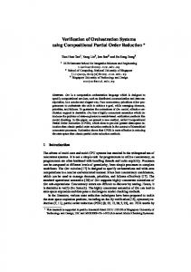
5.1. TLS Components and Style This section introduces the components and the style of the TLS. The architecture of the system is composed by five components that are shown in Fig. 1.
Figure 1. Basic Components of TLS As described in Sect. 3, each component and connector is represented as a hyperedge where its tentacles represent ports. For example, the Supervisor component of Fig. 1 has three ports: supCO, supCam and supT L to connect it to the components CenterOperations, Camera and TL, respectively. As we can see from the typed graph (or style) of Fig. 2, the TLS system is composed of only one CenterOperations component, of one Supervisor, of two TL components, two Camera components, and two optional Car components, one for each TL.
Figure 2. Style of TLS It is important to model how many objects can be connected through an instance of a hyperedge type. AGG allows the specification of the multiplicity of the hyperedges of the typed graphs. Expressing a multiplicity at the target end of a hyperedge type means specifying the number of nodes which may be connected to the source node across hyperedges of the given hyperedge type. A multiplicity at the source end of a hyperedge type is interpreted similarly. For instance, by referring to Fig. 2, the SupT L tentacle (port) is attached with the component Supervisor at its source, and with two connections T L−Supervisor at its target. Each T LSup hyperedge is attached with the component TL at its source, and with the connection T L−Supervisor at its target. Setting multiplicities in AGG has several positive effects since they pose additional constraints on a hypergraph: 1) the number of NACs for rules might decrease; 2) the number of consistency conditions might decrease; 3) the efficiency of the critical pair analysis might increases.
Points 1 and 2 are important since those are the instruments that we use to check correctness and completeness of our grammar and then decreasing the number of NACs and consistency conditions means decreasing the amount of work to the programmer. As explained in Sect. 4, AGG enables attributing nodes and tentacles. This is very useful especially for expressing consistency conditions of the grammar. In the TLS, the component TL has three Boolean attributes: onGreen, onRed and inf raction. They express whether a green/red light is on/off and whether there is an infraction going on. The ports TLSup and CamSup have also the signal Boolean attribute. This is used to model whether or not there is a communication between TL and Supervisor or between Camera and Supervisor. Figure 3 shows an example of a style-conformant configuration of the TLS composed of two traffic lights (i.e., TL). It could represent the model of a crossroad with two traffic lights.
Figure 4. Rule oneCar of TLS link4 . The production presented in Fig. 4 shows the situation in which a Car component is added to the TLS. This means that the biggest amount of traffic is in that specific TL. Therefore, the addition of a Car means switching the TL attribute onGreen from false to true, and the attributes onRed from true to false. Attributes of the components in the left hand-side are set to values required for this situation. This rule cannot be applied when there is another TL such that onGreen==true. Additionally, the NAC TLsignalFalse controls the rule application by preventing that the rule is applied when at least one TL component does not send a signal. The left hand-side production presented in Fig. 5 models the situation in which the system changes its status from a desirable one into an undesirable one. Here, the system is in a status where the signal emitted by TL is correctly received and it goes to a status where the signal from TL is lost. Then, the component TL cannot communicate with the rest of the system. The right handside instead models the situation in which the system goes from an undesirable status in which the signal from TL is lost, to a desirable one, where the signal is re-established.
Figure 3. A configuration of TLS
5.2. TLS Productions The set P R of productions of GT LS models the following system configurations: • Switching: the system switches between green/red light based on the traffic flow; • Light Check: the system checks that each cross road has only one green light turned on; • Infraction management: whether there is an infraction the system has to trigger the camera; • Loss of traffic light signal: if there is a loss of a traffic light signal, the system tries to repair it; • Loss of Camera signal: if there is a loss of Camera signal, the system tries to repair it. As shown in Sect. 3 the set of possible productions is composed of three subsets: Programmed (P Rpgm ), Environment (P Renv ) and Repairing (P Rrpr ). In the following we describe only one production for each subset and remand the reader to see the complete case study at the following
Figure 5. Rules failureTL and repairTL of TLS
6. TLS Validation Using AGG In this section we show how the analysis feature of AGG can be used for self-repairing system specifications in order to check it for correctness and completeness. In the following we start briefly describing how the TLS is implemented in AGG. Then we show how AGG is used to validate the system specification.
6.1. TLS Implementation in AGG The TLS is represented by a Typed Attributed Graph Grammar. In the Type Graph (Style) shown in Fig. 2, each 4. www.antoniobucchiarone.it/TLSCaseStudy/WICSA09.zip
component of the system is represented by a hyperedge with a label. Each tentacle, represented by an edge, represents each single port of communication. Moreover, nodes and edges are attributed and multiplicity constraints are defined. The productions of the TLS are Typed Attributed Rules in AGG. Most rules of the TLS are equipped with one or more NAC. Attributes, multiplicities, and NACs are very useful for expressing consistency conditions of the TLS. Finally, we defined some graph consistency constraints for the grammar. They specify global properties of the TLS which must be satisfied to guarantee the validity of the system.
p2 ∈ P Rrpr no dependency can be found, then the normal (programmed) rules do not enable application of repairing rules. Once a repairing rule is applied, the configuration becomes correct again and a programmed rule is applicable. The dependency analysis results show that the dependency (change - use attribute) exists for each pair of rules (p1 , p2 ) with p1 ∈ P Rrpr and p2 ∈ P Rpgm . When there is no dependency of repairing and programmed rules then we cannot say nothing or not so exactly about relations of repairing and programmed rules. Moreover, each repairing rule is in conflict with itself since a repairing rule prevents the applicability of itself.
Figure 6. Graph consistency constraint allGreen of TLS Figure 6 shows an atomic graph constraint, called allGreen, which is used in a Boolean constraint, called oneGreen. oneGreen, in the form of ¬allGreen, is defined in order to forbid any configuration that has two contemporary TLs such that onGreen=true and onRed=f alse. The premise of this graph constraint is given by an empty graph. Once the conclusion is found, the Boolean constraint oneGreen fails and then it prevents a rule application which causes an inconsistent configuration. Table 1 summarizes the aspects of TLS formalization and its corresponding implementation in AGG. Informal Aspect Comp and Conn Port and Role SA Configuration Comp/Conn Connections Architectural Style Style-compliant SA configuration SA reconfiguration
DSA
Formalization Hyperedge Hyperedge Tentacles Hypergraph Node
AGG Implementation Nodes and Edges Edge with Node Directed Graph Node
Hypergraph Typed Hypergraph
Type Graph Typed Attributed Graph Partial, injective typed attributed rules Typed Attributed Graph Grammar
Partial, injective morphism of T-typed hypergraphs T-typed hypergraph grammar
Table 1. Relations between formalization and AGG implementation
6.2. Repairing dynamism validation The formalization of completeness and correctness of a repairing dynamism specification is explained in Sect. 3. The verification of completeness can be performed in AGG by means of critical pair analysis. More precisely, if for each pair of rules (p1 , p2 ) with p1 ∈ P Rpgm and
Figure 7. Dependency Matrix of TLS in AGG The verification of correctness can be described in terms of critical pair analysis as following: for each pair of rules (p1 , p2 ), with p1 ∈P Renv and p2 ∈P Rrpr there must exist a dependency (i.e., change - use attribute). This means that after application of an environment rule, which destroys a consistent configuration, an opposite repairing rule is applicable to restore consistency of this configuration. Moreover, each environment rule is in conflict with itself since an environment rule prevents applicability of itself. It is important to note that, each pair (p1 , p2 ) whit p1 ∈Penv and p2 ∈Ppgm are in conflict because of the nature of the environment. For example, once the rule failureTL is applied, the signal of TL component is lost and it cannot communicate with the rest of the system. The traffic will stop and wait for the rule repairTL, which repairs invalid configuration and enables application of normal (programmed) rules. The results of the verification of critical pairs performed in AGG are shown in Fig. 7 and in Fig. 8. In Fig. 7, the colored fields represent dependencies, while the colored fields of the table in Fig. 8 represent the conflicts. As an example of the performed analysis, let us consider the critical pair (failureTL, oneCar). Figure 9 shows a conflict situation (the bold TLSup edge with the attribute signal=true). The rule failureTL changes the attribute value from true to false and this impedes the application of the rule oneCar since it needs this attribute set to true.
Figure 8. Conflict Matrix of TLS in AGG Figure 10. Dependency of rules (repairTL, oneCar) set Ec (GS ) is empty. The verification of correctness of the S(GS ) using critical pair analysis can be reduced to check if for each pair (p1 , p2 ) whit p1 ∈P Rpgm and p2 ∈P Rrpr no dependencies exist. Considering the critical pairs for TLS in Fig. 7, we do not find any dependency rule pair with the first rule from the set P Rpgm ({oneCar,. . .,infractionOff }) and the second from the set P Rrpr ({repairTL, repairCam}). In other words, each production of self reconfiguration does not produce configurations that need to be repaired. The verification of completeness in the context of self dynamism is similar to the verification of completeness performed for repairing dynamism, as described in Sect. 6.2. Figure 9. Conflict of rules (failureTL, oneCar) Figure 10 shows a dependency situation of the pair (repairTL, oneCar). Rule repairTL changes the attribute value from false to true and this restores the configuration in which the rule oneCar is applicable again. Analyzing critical pairs which represent analogous situations we can see that all conflicts which are caused by the environment rules (failureTL, failureCam) will be resolved by the repairing pair (repairTL, repairCam).
6.3. Self dynamism verification The formalization of completeness and correctness in the context of self dynamism of DSA is described in Sect. 3.2. We recall that S(GS ) and Ec (GS ) are subsets of R(GS ), where S(GS ) are self reconfigurations by applying autonomous changes, Ec (GS ) are reconfigurations by applying an external sequence of commands, and R(GS ) is the set of all reachable configurations. In our case study the TLS non-deterministically selects a rule to be applied. Therefore, the set S(GS ) is the set of all configurations reachable by applying autonomous changes. It can be associated to our TLS grammar which defines self dynamism with autonomous repairing mechanism. The
7. Conclusion In this paper we have presented a way to model selfrepairing systems using Dynamic Software Architectures (DSAs) formalized as T -typed hypergraph grammars and implemented in a unique framework called AGG. AGG has been used to verify correctness and completeness of these models in an easy way. Future work concerns the extension of the modeling approach to model and analyze hierarchical DSAs that have as basic elements more complex and structured components. We plan to use hierarchical hypergraphs [27] in which each hyperedge can represent relations among components. In this paper we have not taken into account the behavior of components and connectors. As future work we will investigate mechanisms to support the adaptation of the system behavior. This research line will build on previous results: (i) [28] that presents an approach to efficiently (and still maintaining the required properties) manage the whole reconfiguration of the system when one or more components need to be updated; (ii) [29] that proposes a theoretical assume-guarantee framework that allows one to efficiently define under which conditions adaptation can be performed by still preserving the desired invariant.
Acknowledgments This work is partly supported by the Italian PRIN d-ASAP and from the European Community’s Seventh Framework Programme FP7/2007-2013 under grant agreement 215483 (S-Cube) projects.
References [1] B. H. C. Cheng, H. Giese, P. Inverardi, J. Magee, and R. de Lemos et al., “08031 – software engineering for self-adaptive systems: A research road map,” in Software Engineering for Self-Adaptive Systems, ser. Dagstuhl Seminar Proceedings, no. 08031, 2008. [2] R. Allen, R. Douence, and D. Garlan, “Specifying and analyzing dynamic software architectures,” in FASE’98, 1998. [3] J. Andersson, “Issues in dynamic software architectures,” in Int. Software Architecture Workshop, 2000, pp. 111–114. [4] L. Baresi, R. Heckel, S. Thone, and D. Varro, “Style-based refinement of dynamic software architectures,” in WICSA’04. Washington, DC, USA: IEEE Computer Society, 2004.
[14] M. Shaw and D. Garlan, Software Architecture: Perspectives on an Emerging Discipline. Prentice Hall, April 1996. [15] R. Morrison, D. Balasubramaniam, F. Oquendo, B. Warboys, and R. M. Greenwood, “An active architecture approach to dynamic systems co-evolution,” in ECSA, 2007, pp. 2–10. [16] R. Chatley, S. Eisenbach, J. Kramer, J. Magee, and S. Uchitel, “Predictable dynamic plugin systems,” in FASE, 2004. [17] D. Hirsch, J. Kramer, J. Magee, and S. Uchitel, “Modes for software architectures.” in EWSA’06, 2006. [18] M. Endler, “A language for implementing generic dynamic reconfigurations of distributed programs,” in BSCN’94, 1994. [19] P. Koopman, “Elements of the self-healing system problem space,” in WADS03, 2003. [20] S.-W. Cheng, D. Garlan, and B. Schmerl, “Architecture-based self-adaptation in the presence of multiple objectives,” in SEAMS’06. New York, NY, USA: ACM, 2006, pp. 2–8. [21] M. Autili, P. Inverardi, and P. Pelliccione, “Graphical Scenarios for Specifying Temporal Properties: an Automated Approach,” Automated Software Engineering (ASE), vol. 14, no. 3, pp. 293–340, September 2007.
[5] M. Hadj Kacem, M. Jmaiel, A. Hadj Kacem, and K. Drira, “Evaluation and comparison of adl based approaches for the description of dynamic of software architectures,” in ICEIS’05. USA: INSTICC Press, 2005, pp. 189–195.
[22] A. Bucchiarone, “Dynamic software architectures for global computing systems,” Ph.D. dissertation, IMT Institute for Advanced Studies, Lucca, Italy, 2008.
[6] D. Garlan and B. Schmerl, “Model-based adaptation for selfhealing systems,” in WOSS ’02. ACM, 2002, pp. 27–32.
[23] A. Habel, R. Heckel, and G. Taentzer, “Graph grammars with negative application conditions,” Fundamenta Informaticae, vol. 26, pp. 287–313, 1996.
[7] D. Garlan, S.-W. Cheng, A.-C. Huang, B. Schmerl, and P. Steenkiste, “Rainbow: Architecture-based self-adaptation with reusable infrastructure,” Computer, vol. 37, no. 10, pp. 46–54, 2004.
[24] R. Heckel and A. Wagner, “Ensuring consistency of conditional graph rewriting - a constructive approach,” Electr. Notes Theor. Comput. Sci., vol. 2, 1995.
[8] J. S. Bradbury, J. R. Cordy, J. Dingel, and M. Wermelinger, “A survey of self-management in dynamic software architecture specifications,” in WOSS ’04. ACM, 2004, pp. 28–33.
[25] J. H. Hausmann, R. Heckel, and G. Taentzer, “Detection of conflicting functional requirements in a use case-driven approach,” in ICSE 2002. ACM Press, 2002, pp. 105–115.
[9] M. Wermelinger, “Towards a chemical model for software architecture reconfiguration,” in CDS ’98. IEEE Computer Society, 1998, p. 111.
[26] L. Lambers, H. Ehrig, and F. Orejas, “Efficient conflict detection in graph transformation systems by essential critical pairs,” Electron. Notes Theor. Comput. Sci., vol. 211, pp. 17– 26, 2008.
[10] R. Bruni, A. Bucchiarone, S. Gnesi, and H. Melgratti, “Modelling dynamic software architectures using typed graph grammars,” ENTCS, vol. 213, no. 1, pp. 39–53, 2008.
[27] B. H. F. Drewes and D. Plump, “Hierarchical graph transformation,” J. Comput. Syst. Sci., vol. 64, pp. 249–283, 2002.
[11] R. Bruni, A. Bucchiarone, S. Gnesi, D. Hirsch, and A. Lluch Lafuente, “Graph-based design and analysis of dynamic software architectures.” Berlin, Heidelberg: SpringerVerlag, 2008, pp. 37–56. [12] D. Jackson, Software Abstractions: Logic, Language, and Analysis. The MIT Press, 2006. [13] M. Clavel, F. Dur´an, S. Eker, P. Lincoln, N. Mart´ı-Oliet, J. Meseguer, and C. Talcott, All About Maude - A HighPerformance Logical Framework: How to Specify, Program, and Verify Systems in Rewriting Logic. LNCS, 2007.
[28] P. Pelliccione, M. Tivoli, A. Bucchiarone, and A. Polini, “An architectural approach to the correct and automatic assembly of evolving component-based systems,” J. Syst. Softw., vol. 81, no. 12, pp. 2237–2251, 2008. [29] P. Inverardi, P. Pelliccione, and M. Tivoli, “Towards an assume-guarantee theory for adaptable systems,” in SEAMS2009, 2009.