RV’04 Preliminary Version
Semantics and Runtime Monitoring of TLCharts: Statechart Automata with Temporal Logic Conditioned Transitions Doron Drusinsky 1 Computer Science Department, Naval Postgraduate School, Monterey, CA, USA Time Rover Inc., Cupertino, CA, USA
Abstract This paper describes the semi-formal semantics and a run-time monitoring technique for TLCharts, a visual specification language that combines the visual and intuitive appeal of non-deterministic Harel Statecharts with formal specifications written in Linear-time (Metric) Temporal Logic (LTL and MTL). We describe an automata-theoretic semantics for non-deterministic statecharts with negation and state overlapping and extend it to cater for temporally annotated transitions, thereby providing a simple automata theoretic semantics for TLCharts. We also describe a run-time monitoring technique for TLCharts. Key words: Harel Statecharts, temporal logic, finite automata, semantics, formal specification
1
Introduction
Temporal Logic is a special branch of modal logic that investigates the notion of time and order. Linear-time Temporal Logic (LTL) is an extension of propositional logic where, in addition to the well-known propositional logic operators, there are four future-time operators (♦-Eventually, 2-Always, U Until, O-Next) and four dual-past time operators. Pnueli [Pn] suggested using LTL for reasoning about concurrent programs. Since then, several researchers have used LTL to state and measure correctness of concurrent programs, protocols, and hardware (e.g., [MP, Pn]). Metric Temporal Logic (MTL) was suggested by Chang, Pnueli, and Manna as a vehicle for the verification of real time systems [CPM]. MTL extends LTL by supporting the specification of relative-time and real-time constraints. With MTL, all four LTL futuretime operators can be characterized by relative-time and real-time constraints, 1
Email:
[email protected] This is a preliminary version. The final version will be published in Electronic Notes in Theoretical Computer Science URL: www.elsevier.nl/locate/entcs
Drusinsky
specifying the duration of the temporal operator. Temporal Logic with Time Series constraints (TLS) was suggested by Drusinsky [D2] as an extension of MTL which enables temporal specifications that assert about time-series properties such as stability, monotonicity, and min-max values. Ever since first published [Ha], and later incorporated into the OMT methodology and UML standard, Harel statecharts have been described in numerous papers and books (e.g., [Br, RB]). Statecharts extend finite state diagrams with hierarchy (state nesting), concurrence, and history states. Harel Statecharts are typically used for design analysis and implementation; for example, Brugge suggests using statecharts in the design analysis phase of an object oriented UML based design methodology [Br]. A formal semantics of Harel statecharts has been suggested in [HN]. This paper uses new a automata theoretic semantics for statecharts first suggested in [D1]. The semantics lends itself to the inherently non-deterministic semantics required by the TLCharts formalism. It also supports statecharts and TLCharts with overlapping states. Timed automata extend non-deterministic automata with timed transitions, similar to the timeout event mechanism of Harel statecharts [AD]. With TLCharts MTL conditions can be used in addition to timeout events. This is an important feature because the LTL until operator can neither be simulated in a trivial way by timed automata, nor can nesting of temporal operators. Sowmya and Ramesh suggested in [SR] to use temporal logic assertions with statechart qualities by applying temporal logic in a hierarchical manner; the resulting language is a new hierarchical form of the textual temporal logic formalism. In comparison, our hybrid language is a true automata-theoretic hybrid with a unified syntax and semantics; the resulting language is highly visual and familiar, with special LTL annotation of some transitions. Enciso et-al. [E] suggest LNint-e, a logic that enables statecharts to temporal logic transforms using a new temporal logic which combines points and intervals to specify the dynamic behavior of programs. In contrast, our suggested language maintains, for the most part, the syntax and semantics of both languages and retains the visual appeal of statecharts. The Mathworks’ Stateflow statechart tool has a so-called temporal logic extension. Stateflow events and conditions can use the four operators after, before, at, and every. These four operators are essentially extended versions of the LTL eventuality operator. Most notably, the Stateflow formalism lacks non-determinism, negation, and an operator equivalent to LTL’s Until operator. Non-deterministic Finite Automate (NFA) are sometimes used as a specification language [HU]. The TLChart formalism suggested in this paper extends the NFA formalism in two ways: it suggests using non-deterministic statecharts instead of flat and sequential NFA formalism, and supports the annotation of transitions with LTL, MTL and TLS conditions. Existing commercial tools such as the Temporal Rover [D5] provide support for LTL and MTL assertion checking within statechart states. Such a tool 3
Drusinsky
synergy is less effective than a unified formalism suggested in this paper in that it does not provide semantics for the hybrid language and does not enable unrestricted hybrid representations, such as the statecharts transition function using MTL guards. In this paper we describe TLCharts, a formalism that visually and intuitively resembles Harel statecharts while enabling temporal-logic conditioned transitions; similar semantics supports a hybrid of statecharts and extended regular expressions. Such hybrids are useful for the specifying abstract nondeterministic temporal properties inside a statechart specification. Our primary motivation for developing the TLCharts specification language is the concern for effective, early phase specifications, namely system specification that is performed before system design and implementation. This is different than the most prevalent application of formal specifications, which is mostly concerned with the specification of correctness properties for a given, existing, system.
2
An Entry System Control Example
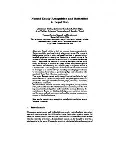
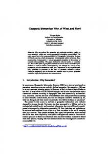
The entry example consists of the following four conditions: (system) begin, (system) end, keyPressed, doorOpen (where doorClosed = ¬doorOpen) and alarm. A particular requirement of interest is: R: a session is the interval between a begin and an end-condition. For every such session a keyPressed must be repeatedly sensed within two-minute intervals or else an alarm must sound within 10 seconds until keyPressed is sensed. Also according to this specification, once the alarm sounds then the assertion has succeeded and no more alarms are permitted. The end-condition is defined to be true whenever there is an interval which starts with the door closed followed by an end being repeatedly sensed until a later time when begin is sensed. We refer the reader to the infusion pump example of [D3] which consists of a requirement similar to R. This reference also contains an LTL/MTL specification for the infusion pump requirement and analyzes subtle specification errors that result from the use of linear time temporal logic. A deterministic Harel statechart specification of requirement R is illustrated in Fig. 1. The discussion in [D3] compares the accuracy of the statechart of Fig. 1 with that of the TLChart of Fig. 2. Fig. 1 and Fig. 2 are both legal TLCharts, i.e. Harel statecharts are a special case of TLCharts, and so are LTL and MTL assertions (using a diagram with a single state and transitions annotated with LTL). TLChart extend Harel statecharts in the following ways: (i) Some transitions are annotated with LTL, MTL or TLS conditions, such as the transition labeled alarm U keyPressed in Fig. 2. (ii) TLChart’s support non-deterministic behavior. 4
Drusinsky
(iii) TLCharts flavor of non-determinism incorporates the specification of both good and bad computations with ambiguities resolved via a prioritybased resolution scheme. From an automata theoretic perspective this amounts to existential non-determinism with negation. (iv) TLCharts can have overlapping states.
Fig. 1. Deterministic Harel statechart specification for requirement R. A Harel statechart is by definition also a TLChart.
Fig. 2. TLChart specification for requirement R1 (all states other than Error are good states; all states with no specified priority have default, i.e., lowest, priority).
5
Drusinsky
A TLChart input string represents a sequence of combinations of stimuli and corresponding system responses; for example, a sequence may contain keyPressed - generated by the environment, as well as alarm - a system generated response. The TLChart of Fig. 2 describes legal (accepted) and illegal (rejected) sequences. From a verification standpoint, a rejected string means that the systems behavior does not comply with the specification, typically due to an incorrect system reaction to the input stimuli. This application of diagrams to specification rather than programming and design explains the existence of a sink state (the Error state), which does not typically exist in a design phase statechart.
3
TLCharts: Syntax and Semantics
3.1 Syntax In this paper we consider Harel statecharts as first described in [Ha], including state hierarchy, concurrence, and history states. Hence, no state overlapping is permitted; this assumption will be changed in the next section. For simplicity, we assume that statechart transitions are annotated with conditions and no events, although we expect TLChart to be used and applied with events and conditions, much like UML statecharts. We use the automata-theoryoriented notation where transitions are annotated with symbols from a finite input alphabet Σ. A practical generalization of the automata model is to use the power set of Σ as the actual input alphabet; this generalization enables multiple simultaneous input channels to the statechart device. Consequently, transition labels are subsets of Σ, where a transition labeled label means informally that all symbols s∈label must be concurrently present on the input tape for the transition to be traversed. TLChart transitions are annotated with one or both of the following types of conditions: propositional and temporal. Propositional conditions are subsets of Σ. Temporal conditions include all legal LTL and MTL formulae. In Fig. 2 temporal conditions are represented using curly braces. Hence [end {end U begin}] represents the propositional condition end and the temporal condition end U begin. When using (extended) regular expressions instead of LTL the equivalent condition is [end {end* begin}]. A TLChart without state overlapping induces an and/or state tree as illustrated in Fig. 3. A TLChart with overlapping states, such as the TLChart of Fig. 4, induces an and/or state Directed Acyclic Graph (DAG), as illustrated in Fig. 5. 3.2 Semantics without Temporal Conditions The TLChart formalism specifies requirements using formal languages. The semantics of a TLChart is interlingua-based, using an Equivalent Non-Deterministic Automaton (ENFA) [D1, HU]. Once defined in terms of its ENFA, a TLChart 6
Drusinsky
Fig. 3. State and/or tree for Fig. 2.
defines correctness properties in a manner that resembles formal logic specification, such as temporal logic specification. It observes a given input tape and decides whether this tape is acceptable or not. In real life terms the input tape corresponds to a combined sequence of inputs to-, and manifested outputs from-, a given system. Definition 3.1 A configuration C is a subset of the TLChart state set in which states of C are pairwise orthogonal, i.e., if for every pair r, s ∈ C, the least common ancestor of randsin the state tree is an and state. Definition 3.2 A configuration C is maximal if it is not a subset of any other configuration with a larger cardinality. For example, in Fig. 2, the configuration {Wait-For-KeyPressed } is not maximal while {Wait-For-KeyPressed, Closed } and {Wait-For-KeyPressed, Open} are maximal. Note that state configurations do not, in general, contain information about corresponding superstates, such as Wait-For-KeyPressed and Closed residing under State-2, which in turn resides under State-1. This information is not necessary because, absent state overlapping, state hierarchy is unique. However, we will change this notation when we describe TLCharts with overlapping states. The ENFA’s state set consists of all possible maximal configurations. Intuitively, this set represents a Cartesian product of state sets of concurrent TLChart threads. We denote a TLChart state within a configuration C as a 7
Drusinsky
constituent of C. As a preliminary step, before we describe the ENFA’s transition relation, note that we can replace statechart and TLChart hierarchical transitions, such as State-1→Init in Fig. 2, with concurrence, using a new concurrent thread with one inner state, e.g. State-1a. The hierarchical transition is then replaced with the transition State-1a →Init. Also, in the following discussion we represent TLChart transitions as annotated binary relations over configurations. For example, in Fig. 1, the hyper edged transition labeled begin is the annotated relationship ({CLS, State-4 }, {Init})begin and, in Fig. 2, the transition Closed → Init is represented by the annotated relationship ({Closed }, {Init})end,endU begin . For simplicity, we will first define consider TLCharts with no temporal conditions Definition 3.3 A global transition is an annotated binary relationship between configurations. Definition 3.4 Given a TLChart transition (b’,c’)a’ we say it is a member TLChart-transition of a global transition (b,c)a if b’⊆ b, c’⊆ c, and a’⊆ a. Given a global transition t=(b, c)a we denote its set of member TLChart transitions as m(t). For example, in Fig. 1, t= ({OPN, State-3 }, {CLS, State-4 }{doorClosed,end}is a global transition, where OPN→doorClosed CLS and State-3 →end State-4 are two members of t. Definition 3.5 Let (b′ , c′ )a′ be a member transition of some transition (b, c)a , then every state in b′ (c′ ) is said to be a source (target) state in b (c), and we denote the set of all source (target) states for (b, c)a as the source (target) set of (b, c)a . Note that member TLChart transitions of a global transition t=(b, c)a are always non-conflicting otherwise c would not be a valid configuration. Definition 3.6 A global transition t1 =(b, c)a is maximal if (i) b and c are maximal configurations, and (ii) no other global transition t2 =(b, e)a exists such that m(t1 ) ⊂ m(t2 ). Intuitively, t1 pairs maximal configurations b and c by firing a maximal set of non-conflicting TLChart transitions that are enabled in configuration b using the inputs symbols in a. For example, in Fig. 1, ({OPN, Wait-ForKeyPressed, State-3 }, {CLS, Wait-For-KeyPressed, State-4 }{doorClosed,end} is a maximal transition but ({OPN, Wait-For-KeyPressed, State-3 }, {CLS, WaitFor-KeyPressed, State-3 }{doorClosed,end}is not maximal because it did not fire the enabled TLChart transition State-3 →end State-4. ENFA transitions extend maximal transitions in that they might affect states in an indirect way, i.e., without those states being source or target states of any member transition. To this end, we need a few more definitions. Recall that a statechart (are therefore a TLChart) default state is a designated initial state within a particular level of nesting. Hence, we define the 8
Drusinsky
following. Definition 3.7 A state d is default under state s if d is a descendant of sin the state tree, d is a default state, and all ancestors of d under s are default states. A state d is a default state under a configuration C if d is a default state under the least common ancestor (lca) of the elements of C in the state tree. In Fig. 2 for example, state Closed is default under state Door Thread, but not default under the TLChart root. Finally, we define ENFA transitions. Definition 3.8 Let t=(b, c)a be a maximal transition and let b′ , c′ be the source and target sets of t, respectively. t is a legal ENFA transition if for every state s ∈ c − c′ (i.e., s is in c but is not an explicit target state of some member transition), s is a default state under c or else s ∈ b − b′ (i.e., s was not affected by the transition). For example in Fig. 1, the maximal transition ({Init}, {CLS, For-KeyPressed, State-3 }{begin} is an ENFA transition where the least common ancestor of configuration {CLS, Wait-For-KeyPressed, State-3 } is state State-1, and CLS, For-KeyPressed, and State-3 are all defaults under State-1. Note that conflicting simultaneously enabled ENFA transitions induce nondeterminism. This is the case in the TLChart of Fig. 2 when keyPressed, doorOpen, and alarm are all true while in configuration {Closed, Wait-ForKeyPressed } enabling two ENFA transitions, one resulting in configuration {Open, Wait-For-KeyPressed } while the other results in configuration {Error }. 3.3 Semantics with Temporal Conditions While standard semantics for LTL are defined using infinite models, in this paper our primarily interest is with finite linear model semantics. Hence, for example, Eventually ρ is satisfied if there exists state s in the finite linear model that satisfies ρ. An LTL model relates to an automatons input tape in the following straightforward way. An LTL model consists of a finite sequence of states with Boolean propositions and corresponding truth assignments assigned to each state. For example, consider a model with two states (i.e., two cycles), where {begin, ¬end, KeyPressed, ¬alarm, doorOpen} is the truth assignment for state 0 (interpreted as cycle 0), and {¬begin, ¬end, KeyPressed, ¬alarm, doorClosed } is the truth assignment for state 1. This model is therefore obviously exchangeable with an automaton input tape with the symbol in position 0 and in position 1. In other words, each Boolean proposition pi and its negation ¬pi form an alphabet Σi . The input alphabet Σ for the ENFA is then the Cartesian product of all Σi alphabets. We now incorporate temporal conditions into ENFA behavior. First, note that every ENFA transition has a pair of propositional and temporal condi9
Drusinsky
tions, which are the respective conjunctions of all propositional and temporal conditions annotating its member TLChart transitions. Hence we represent an ENFA transition as an annotated binary relation (b, c)a,ρ where a is a propositional condition and ρ is a temporal condition. Temporal conditions affect ENFA behavior via the definition of a computation. Given an input tape, a conventional one-way non-deterministic Finite Automaton (NFA) computation is essentially a sequence of consecutive transitions and corresponding tape head moves to the right; details are available in [HU]. ENFA’s extend this well known definition by requiring that for every transition ti in the computation the input tape is observed from position i into the future and back to the past, but without moving the tape head. The transition ti is then enabled only if the temporal condition is satisfied by the tape, while considering position number i as cycle 0. Definition 3.9 Let σ = σ1 .σ2 ...σn be an input tape and let C = c0 .c1 . . . cn be an ENFA computation. C is a computation on σ if c0 is an initial configuration and ∀i, 0< i ≤ n,the ENFA contains a transition (ci−1 ,ci )a,ρ such that a ⊆ σi ,and σ,i |=ρ using standard LTL and MTL semantics (e.g., [CPM]). For example, using the entry system TLChart of Fig. 2, consider the input tape (using straightforward abbreviations of the entry system conditions): σ = σ1 .σ2 .σ3 .σ4 .σ5 .σ6 = {B,¬E,KP,¬A,DC }.{¬B,¬E,¬KP,¬A,DC }. {¬B,¬E,KP,¬A,DO}.{¬B,¬E,KP,A,DC }. {¬B,E,¬KP,¬A,DC }.{B,¬E,¬KP,¬A,DO}. The following C1 computation is enabled by σ; each line is considered as a cycle, starting at cycle 0: {Init}→B {Wait-For-KeyPressed, Closed }→(none) {Wait-For-KeyPressed, Closed }→KP,DO {Wait-For-KeyPressed, Open}→A {Error} (a sink state) Similarly, the following C2 computation is also enabled by σ: {Init}→B {Wait-For-KeyPressed, Closed }→(none) {Wait-For-KeyPressed, Closed }→KP,DO {Wait-For-KeyPressed, Open}→KP,DC {Wait-For-KeyPressed, Closed }→ρ {Done} where ρ is the temporal condition E U B. ρ is enabled on cycle 4 because the input tape then points to σ5 and the tape suffix is σ5 .σ6 = {¬B, E,¬KP,¬A,DC }.{B,¬E,¬KP,¬A,DO} which satisfies ρ. Like their logical counterpart, ENFAs represent assertions about a system. They do so using a formal language mechanism, namely by accepting or rejecting strings (tapes). A classical NFA accepts a string using an existential criterion, namely, if a computation ending in a final state exists. A dual uni10
Drusinsky
versal automaton (∀-FA) accepts a string if all computations end in a final state. Combining both acceptance criteria results in an alternating automaton. Alternatively, an existential NFA with negation can be used instead of a combination of both acceptance criteria. ENFA supports negation using (i) negation inside temporal conditions, (ii) a combination of good (accepting) and error (rejecting) states. For a given input string san ENFA has one or more possible computations on s, some of which end in a good state while others end in an error state. Conflicts are resolved using a priority scheme where the winning computation is the computation whose last visited state configuration contains a TLChart state St whose priority is higher than all other TLChart states in all competing configurations. If St is a good state then the TLChart accepts the input string otherwise the TLChart rejects it. For example, in Fig. 2 consider two computations on the input string σ described earlier, C1 and C2. C1 ends in the configuration {Error } where the error state Error has priority 2. C2 ends in the configuration {Done} where good state Done has priority 1. We use the engineering convention where lower integer values represent higher priorities; hence, σ is accepted because Done has a higher priority than Error. Whenever the priority scheme cannot resolve conflicts we arbitrarily select the error computation as overriding. Likewise, whenever a single computation ends in a configuration that contains both good and error states, then we arbitrarily select the error state as overriding. TLCharts support methods for real-time constraint specification. The first method uses Harel statechart timeout (tm) events, not unlike the mechanism used by timed automata. The second method uses MTL; consider a variant of Fig. 2 where the pair of transitions Wait-For-KeyPressed →tm(2min)AlarmNecessary, and Wait-For-KeyPressed →keyP ressed Wait-For-KeyPressed are replaced with a single transition Wait-For-KeyPressed →ρAlarm-Necessary, where ρ = ¬♦≤2min keyPressed. Though similar, the two approaches differ with respect to the timing in which state Alarm-Necessary is reached. With the first representation Alarm-Necessary is reached after two minutes, while under second representation the transition is traversed after one cycle. In this context, we suggest a special visual delay construct, represented with thick edges, which can only be used with the following unnested temporal conditions: 2≤d ρ (2ρ with an MTL upper bound d), ♦ρ, and ρU ψ. It means that the transition is traversed only when the temporal condition becomes true, i.e., when the MTL upper bound d in for 2≤d ρ is reached, or when ψ is true in ♦ψ or ρU ψ. Hence, in Fig. 2, the transition Done→alarm Error is enabled only after the final keyPressed input that satisfies the preceding transitions’ temporal condition (alarm U keyPressed ) is detected. A thick transition A →ρU ψ Bis formally but a shorthand representation of a pair of thin transitions A →ρU Oψ A′ andA′ →ψ B,where A’ is a new sibling of A in the state tree. A similar approach is used for the other types of thick transitions. From a semantic perspective, real-time measurements, used by statechart 11
Drusinsky
timeout events and MTL constraints, are represented in our ENFA model using a standard monotonically increasing positive integer function that maps each tape cell with a real-time value. Note that though visually similar to Harel Statecharts, TLCharts are actually used and applied more like a temporal logic specification in the following sense. TLCharts do not describe the token by token reaction of a reactive system to environment stimuli. Rather, TLCharts consider a complete input string s, which combines both environment inputs s in and system outputs s out; a TLChart asserts about the legality of an s out system response to the s in stimuli.
4
TLCharts with Overlapping States.
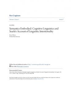
The proposed automata theoretic statechart semantics described in Section 3 caters for statecharts with overlapping states [Ka]. Consider the TLChart of Fig. 4, a variant of the TLChart of Fig. 3 but with overlapping states. In Fig. 4, state State-OVLP is an and state that shares its substates with the concurrent threads of state State-2. Fig. 4 induces the DAG state graph of Fig. 5. The intuitive meaning of the state overlap in Fig. 4 is that it is illegal for a key to be pressed while the valve is open. From a semantics perspective, ENFA state configurations for TLCharts with overlapping states contain all state nesting information. Hence, the situation where State-KP and Open are simultaneously visited has two distinct possible representations as ENFA state configurations: {State-1, State-2, State-KP, Open}, and {State-1, State-OVLP, State-KP, Open}. Therefore, the following two computations are distinct, though when considering only leaf states the cycle #1 configurations look alike: {Init}→B {State-1, State-2, Wait-For-KeyPressed, Closed }→KP,DO {State-1, State-2, State-KP, Open}→DC {State-1, State-2, State-KP, Closed } and {Init}→B {State-1, State-2, Wait-For-KeyPressed, Closed }→KP,DO {State-1, State-OVLP , State-KP, Open}→(any) {Error } Given that the second computation ends in Error, a state with higher priority than any of the states in {State-1, State-2, State-KP, Closed }, the TLChart rejects the input, effectively stating that State-KP and Open cannot be visited simultaneously. Fig. 4 contains another instance of state overlapping, where two or states overlap, namely NoAlarm and State-1. Hence, when state Wait-For-KeyPressed is visited, it can be considered as residing under state NoAlarm or under state 12
Drusinsky
Fig. 4. A TLChart with overlapping states.
Fig. 5. State and/or DAG for the TLChart of Fig. 4.
State-1, each case resulting in a different configuration. Therefore, the following two computations are possible: {Init}→B {State-1, State-2, Wait-For-KeyPressed, Closed }→alarm 13
Drusinsky
{State-1, State-2, Wait-For-KeyPressed, Closed } and {Init}→B {NoAlarm, Wait-For-KeyPressed }→alarm {Error } The formal semantics described earlier is extended to support TLCharts with overlapping states in the following way. Given a TLChart T with overlapping states, we say that T’s state DAG contains the tree Tr, if Tr is a spanning tree in T and is a legal state-tree. Using the existing semantics of Section 3, every state-tree ST i contained in the state DAG induces an ENFA, which in turn induces a set Si of possible, competing, computations; the final outcome of these competing computations is then determined using a priority scheme. The new extended semantics defines the DAG computation set SDAG as the union of allSi sets, and the final outcome is then determined using the priority scheme applied to all computations in SDAG.
5
Armor Plating Specifications
Run time assertion checking is a common method for armor-plating programs against unexpected errors. Recently, in [D4], armor plating method using run-time monitoring of LTL and MTL assertions combined with exception handling was suggested. TLCharts offer an opportunity for armor-plating specifications using overspecification, namely by adding temporal conditions to an otherwise fully specified TLChart or statechart. Consider for example requirement R and the corresponding TLChart of Fig. 2. A correctness property ϕ of interest, expressed in MTL, is that in state Wait-For-KeyPressed : (¬♦≤120 keyPressed ) => ♦[120,130] (alarm U (keyPressed ∧ 2¬alarm). Therefore, Fig. 2 and 4 can be armor-plated with a transition Wait-For-KeyPressed →¬ϕError. This transition overlaps at least two other transitions: (i) it can, with the appropriate conditions, fire together with Wait-For-KeyPressed → Alarm-Necessary → Error, or (ii) it can, with the appropriate conditions, fire together with WaitFor-KeyPressed → Alarm-Necessary → Done→ Error. The purpose of overspecification is therefore to provide additional assurance that a specific requirement is satisfied. A different flavor of armor plating involves the addition of temporal conditions as guards to propositional conditions. Such armor plating is useful when designing an implementation statechart, where is can be used for additional safeguards assuring that the specification is conformed to. For example, the developer of the statechart of Fig. 1 can armor-plate the transition Alarm→keyP ressed Done with the temporal guard ¬♦alarm resulting in the transition Alarm→keyP ressed∧¬♦alarm Done. By doing so the developer has carried a specification requirement into the design level representation all while using a single coherent formalism. 14
Drusinsky
6
Runtime Monitoring of TLChart Specifications
Our runtime monitoring method for TLCharts (with no state overlapping) combines a particular statechart code generation technique with an existing MTL monitoring tool described in [D2, D5]. A corresponding product named the StateRover is currently under development by Time Rover, Inc. The particular statechart Code Generation (CG) algorithm we use is a derivative of a hardware synthesis technique for Harel statecharts described in [D6]. This synthesis technique generates a hardware Programmable Logic Array (PLA) representation of the control logic for a hardware controller implementation of a statechart. A PLA is a two-level sum-of-products Boolean logic device. The PLA implements the logic responsible for configuration changes. Configurations are stored in a state-register. In programming terms each PLA product term corresponds to an if statement in a conventional programming language, while the hardware state register corresponds data store for the Present Configuration (PC). Hence, the entire statechart is represented as a collection of if statements, one per transition in the original statechart, each changing certain states within the PC. We denote each such if -statement as an if-block. An if-block for the Fig. 1 transition {State-4, CLS }→{Init} is: if ((PC[1]==STATE4) && (PC[3]=CLS) && begin)) { // guard PC[0]=INIT; PC[1]=0; // assignment of next PC PC[2]=0; PC[3]=0; } An if-block consists of a guard condition and an assignment of elements of the next PC. TLChart monitoring is performed using CG. The TLChart CG method is a variation of the statechart CG method described earlier with the following modifications: (i) Instead of a single PC data store, the generated code contains a plurality of potential PC data stores; this plurality of PC stores implements non-deterministic behavior, where each PC store stores the present state within a single computation. (ii) If-blocks might contain temporal conditions within their guards. (iii) Each PC store is marked with a tag using one of four values representing the Cartesian product of a logical value (good/error ) and a Boolean finality value (steady/transient). A PC store also contains a simple counter. The logical value of the PC is error if any state of the PC is an error state, or else it is marked as good. The PC finality marking represents the status of a computation with respect to temporal conditions under evaluation. The PC finality marking provides information about the possibility that the PC logical value might change in the future. For example, consider a computation . . . → {Alarm-Necessary} 15
Drusinsky
→alarmU keyP ressed {Done} →alarm {Error} in Fig. 2. If a PC is {Error } then its logical value is error, but if the finality marking is transient it means that the computation has a potential of not reaching the Error state, where the actual outcome depends on the on-going evaluation of a temporal condition such as alarmU keyPressed. Monitoring begins with a set of assigned PC stores, one per initial configuration, all marked as good and steady and having their counters reset to zero. For each configuration PC, a PC change cycle consists of firing all if-blocks, resulting in a change of PC. Hence, a new PC set is induced by the current PC set and the current input symbols. Within a single PC change cycle, the PC holds its value, tag, and counter as generated by the previous change cycle for that PC. Then, each if-block contributes to a change in the PC in the following way. For an if-block that contains only propositional conditions: PC’s counter and tag are not affected. Such an if-block affects the PC contents in an obvious way only if it guard succeeds. For example, for the TLChart of Fig. 2, let PC={Wait-For-KeyPressed, Closed }, then after receiving the input stimuli doorOpen the PC changes to PC={Wait-For-KeyPressed, Open}. Now consider an if-block for a TLChart transition with a temporal condition, such as the transition {Alarm-Necessary}→{Done} of Fig. 2; the guard for this if-block contains the temporal condition ρ = alarm U keyPressed. When the guard executes, it increments the PC’s counter and invokes a code snippet for ρ that is generated by a temporal logic code generator such as the Temporal Rover [D5]. The temporal logic related code executes every cycle and results in one of four values, which combine a Boolean logic (success/fail ) result with a Boolean finality (done/not-done) result describing whether the current logical result can change in the future [D5]. Hence, results from the code snippet for ρ affect the PC in question in one of four possible ways: (i) If the code snippet for ρ results in a fail-done pair then the PC in question is not valid anymore and is removed from the set of possible PC’s. (ii) If the code snippet for ρ results in a success-done pair then the counter for the PC in question is decremented, and the code snippet dies (it will not execute in a future cycle). (iii) If the code snippet for ρ results in a fail-not-done or success-not-done pair then the PC’s finality marking is marked as transient. The PC counter for a particular PC store S counts the number of temporal logic conditions within the computation for S that are still under evaluation. Whenever S is zero it means that no temporal logic code condition within the computation for S is alive; the PC’s finality marking is then marked as steady.
16
Drusinsky
7
Conclusion
Harel statecharts and LTL are well-researched and advocated specification languages for reactive systems. Harel statecharts are widely popular through their UML counterpart. LTL on the other hand, is advocated primarily by the academia. While Harel statecharts are visual and deterministic, LTL is textual, logical and non-deterministic. TLCharts combine both formalisms thereby enabling specifications that are visual but also logical and non deterministic when needed. TLCharts have a straightforward formal automata based semantics that supports a meaningful interpretation of statecharts with state overlapping. With TLCharts, temporal conditions are anchored in states, such as alarm U keyPressed being anchored in the state Alarm-Necessary in Fig. 2. This eliminates the need to use deeply nested LTL, when using the pure LTL alternative, or to provide a fully deterministic statechart, when using the Harel statechart alternative. We call this property just in time TL. In addition, TLCharts enable specification armor plating. Although this paper describes TLCharts as a hybrid of statecharts and temporal logic, the notation can be extended to support regular expressions. In fact, a tool currently under development by Time Rover, Inc., will support both temporal logic and regular expression conditions within TLChart diagrams. Clearly, TLCharts can be abused; a single state TLChart with highly nested LTL and MTL conditions is a legal TLChart and so is a fully deterministic, implementation level detailed, Harel statechart. Further research is needed to establish when each constituent capability of this new formalism actually contributes a significant added value to the specification effort. Separate research, done under the auspices of the Naval Postgraduate School in Monterey, is investigating the application of TLCharts to the ongoing Battle Manager of the U.S. Missile Defense system.
References [AD] R. Alur, and D. Dill, A Theory of Timed Automata, Theoretical Computer Science, 126:183-235, 1994. [ACD] G.S. Avrunin, J. C. Corbett, and M. B. Dwyer- Property Specification Patterns for Finite-State Verification, 2nd Workshop on Formal Methods in Software Practice, March 1998. [Br] B. Bruegge- Object-Oriented Software Engineering: Conquering Complex and Changing Systems, Prentice Hall, ISBN 0-13-489725-0. [CPM] E. Chang, A. Pnueli- Z. Manna - Compositional Verification of RealTime Systems, Proc. 9’th IEEE Symp. On Logic In Computer Science, 1994, pp. 458-465. [D1] D. Drusinsky- On Synchronized Statecharts, Ph.D. Dissertation, Weizmann Institute of Science, 1988. 17
Drusinsky
[D2] D. Drusinsky- Monitoring Temporal Rules Combined with Time Series, Proc. 2003 Computer Aided Verification Conference (CAV), pp. 114-117. [D3] D. Drusinsky- Visual Formal Specification using (N)TLCharts: Statechart Automata with Temporal Logic and Natural Language Conditioned Transitions. International Workshop on Parallel and Distributed Systems: Testing and Debugging (PADTAD), 2004. Invited paper. [D4] D. Drusinsky- Specs Can Handle Exceptions. Embedded Developers Journal, November 2001, pp. 10-14. [D5] D. Drusinsky- The Temporal Rover and the ATG Rover. Proc. SPIN 2000 Workshop. Springer Verlag Lecture Notes in Computer Science, 1885, p. 323-329. [D6] D.Drusinsky- A State Assignment for Single-block Implementation of Statecharts. IEEE Transactions on Computer-Aided Design of Integrated Circuits and Systems 10(12): 1569-1575, December 1991. [DH] D. Drusinsky and David Harel. On the Power of Bounded Concurrency I: Finite Automata. Journal of the ACM, 41(3): 517-539, May 1994. [Ha] D. Harel- Statecharts: A Visual Formalism for Complex Systems, Science of Computer Programming 8, pp. 231-274, 1987 [HN] D. Harel and A. Naamad- The Statemate Semantics of Statecharts. ACM Tran. of Software Engineering and Methodology, 5(4) Oct 1996. [EFHL] C. Eisner, D. Fishman, J. Havlicek, Y. Lustig, A. McIsaac, D. Van Campenhout-Reasoning with Temporal Logic on Truncated Paths, Proc. 2003 Computer Aided Verification Conference (CAV), pp. 27-39. [E] M.Enciso, I. P. de Guzm’an, C.Rossi- Using Temporal Logic to Represent Dynamic Behaviour of UML Statecharts, in: ECOOP 2002 Workshop on Integration and Transformation of UML Models (2002). [HU] J. Hopcroft. and J. Ullman- Theory of Formal Languages and Automata, Addison Wesley, 2’nd edition, 2001, ISBN 0-201-44124[Ka] Kahanna, C.A.- Statecharts with Overlapping States, M.S. Thesis, Dept. of Mathematics and Computer Science, Bar-Ilan University, Ramat-Gan, Israel, 1986 (in Hebrew). [MP] Z. Manna, A. Pnueli - Verification of Concurrent Programs: Temporal Proof Principles, Proc. of the Workshop on Logics of Programs, Springer LNCS, 1981 pp. 200-252. [Pn] A. Pnueli - The Temporal Logic of Programs, Proc. 18’th IEEE Symp. on Foundations of Computer Science, 1977, 46-57. [RB] J. Rumbaugh, M. Blaha, W. Premerlani, E. Frederick, W. Lorensen Object Oriented Modeling and Design, Prentice Hall, ISBN 0-13-629841-9. [SR] S. R. Sowmya and S. Ramesh - Extending Statecharts with Temporal Logic, IEEE Transactions on Software Engineering, Vol. 24, No. 3, March 1998 – 1998.
18