classify the different types of design information that may be considered. ... Various contexts include the artifact's use by people, the artifact's relationship ..... structured representations is a complex data structure consisting of named slots with associated values. .... O' Grady, W.D., Contemporary Linguistics - An Introduction.
INTERNATIONAL CONFERENCE ON ENGINEERING DESIGN, ICED’07 28 - 31 AUGUST 2007, CITÉ DES SCIENCES ET DE L'INDUSTRIE, PARIS, FRANCE
SEMANTICS IN ENGINEERING DESIGN Srinivasan Anandan1, Jonathan Maier1, Vikram Bapat2, Bernhard Bettig3 and Joshua Summers1 1
Department of Mechanical Engineering, Clemson University Mechanical Engineering-Engineering Mechanics Dept., Michigan Technological University 3 Department of Mechanical Engineering, West Virginia University Institute of Technology 2
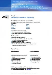
ABSTRACT In engineering design, the concept of semantics is not well-defined as there does not seem to be a clear understanding of how semantic information is currently used in design nor when it should be used. For example, design semantics has been defined as “product and process knowledge which is captured in grounded representations”[1]. One type of product knowledge could be the “design intent” or “design rationale”, whereas a different type could include non-geometric descriptions of the product such as design specifications or function structures. Process knowledge could include knowledge about the manufacturing or design processes used to create the artifact. This paper synthesizes a definition of design semantics based on what information or knowledge can be considered to be semantic through an examination of the various uses of this information. A classification scheme has been proposed to classify the different types of design information that may be considered. Based on this work, it is hypothesized that an approach that facilitates design reasoning with both geometric and semantic information would radically change how engineers design and interact with design tools. Keywords: Semantics, knowledge, context, information modeling 1 MOTIVATION TO MODEL SEMANTICS Current computer-aided-design (CAD) systems typically do not integrate semantic information (what the geometry means to the designer or to the end users with respect to requirements, ramifications to manufacturing, or other product realization concerns) with geometric information. Features technology attempts to bridge this gap, but is limited to finite domains and only for explicitly captured geometric regions of interest. Another example of the semantic gap is that engineering reports are semantically rich but the information contained within is not linked explicitly to the geometric models. This creates a situation where current CAD systems do not allow for artifacts to be placed or maintained in context. Various contexts include the artifact’s use by people, the artifact’s relationship in the environment (especially with respect to sustainability issues), how the artifact is manufactured, and the artifact’s life cycle issues such as maintenance, recycling, eventual disposal, etc. These various contexts for the artifact are semantically rich. A geometric description alone does not carry this semantic information. A thorough review of previous efforts in semantic modeling and our approach is detailed in [2]. A motivating example for this research is the problem of retrieving design exemplars from a database. The Design exemplar is a data structure that is used to represent geometric and parametric design problems [3]. The design exemplar can be used for pattern matching, validation and model modification. There are multiple ways of authoring an exemplar meant for a specific purpose. For example, consider an exemplar authored for finding the distance between two planes. Two ways of authoring such an exemplar are shown below. The exemplar shown in Figure 1a consists of two planes and a distance and a parallel relation between the two planes. The two planes form the match portion of the exemplar, since the planes are explicit in the model. The distance and the parallel relations form the extract portion, since these relations are implicit in the model. On applying this exemplar to the CAD model, distance between all sets of parallel planes are displayed. The value of the distance is stored in the distance parameter, while the ID relation is necessary to display the value. The second exemplar consists of two planes and two points such that they are incident on the two planes. The two points in turn are incident on a line which is perpendicular to one plane. The exemplar also consists of
two surface normals from the two planes that are parallel to each other. In this case, the planes are match whereas the lines, the points, the surface normals, the incidence relations, the distance and the parallel relations form the extract portion. Applying this exemplar to the same model will also give the same results as obtained with the first exemplar. Hence, these two exemplars can be considered similar with respect to the intended use. Match: Plane “P1”; Plane “P2”;
Extract: Parameter “distance”; Direction “V1”; Direction “V2”; Point “point 1”; Point “point 2”; Line “L1”; ID (distance); Distance ({point 1, point 2}, distance); Incident (P1, point 1); Incident (P2, point 2); Incident (L1, point 1); Incident (L1, point 2); Perpendicular (L1, P1); Surface_Normal (V1, P1); Surface_Normal (V2, P2); Parallel (V1, V2);
(a)
Match: Plane “P1”; Plane “P2”;
Extract: Parameter “distance”; ID (distance); Distance ({P1, P2}, distance); Parallel (P1, P2);
(b)
Figure 1. Two exemplars for finding the distance between two planes
However, structurally, these two exemplars are different. This is an example where geometric information alone is not sufficient. However, intended use is just one type of non-geometric and nonparametric information. The rationale for authoring exemplars in a particular manner could also prove useful while retrieving similar exemplars, since it would help the user reason about the usefulness of the retrieved exemplars. Hence, to develop an efficient exemplar retrieval system, it would be necessary to develop an understanding of the different types of semantic information in design. In order to do so, it is necessary to understand to define semantics and classify the various kinds of semantic information. This paper examines the different definitions of semantics in the field of linguistics and the different definitions of design semantics present in literature. A classification of the different types of semantic information in design is also presented. 2. LINGUISTICS: A PRIMER ON SEMANTICS In linguistics, the study of semantics is purely concerned with the meaning of words and how they combine to form words or sentences or phrases [4-6]. Meaning can be defined as a relationship between words and expressions used or it can be indirectly defined by the responses that people make resulting from these words and expressions [4]. Another view of meaning is that it is the mapping between words and expressions and mental images based on previous experience [6]. In this case, meaning of something is defined as the thing it denotes. It is important to note that the words and expressions can imply different meanings within different contexts and for different users. Meaning of a sentence can change depending upon whether it is taken in isolation, whether it is taken in a given context of utterance, or whether it is meant as a form of communication in a social setting [4, 6-8] . This is referred to as the principle of compositionality. It states that the meaning of a sentence is determined by the meaning of its component sections and the manner in which these words are syntactically arranged [9]. For example, the following two sentences mean completely different things because they are arranged differently. • Every student in this university graduates with at least one degree.
• At least one student in this university graduates with a degree. As well, consider the word “design”. This word when taken in isolation may assume different meanings such as the final product or the actual design process. However, when used in a sentence such as, “The focus of this research is to design the cooling system of the car”, it is natural to assume that the word refers to the actual design process. In other words, “semantics” may mean different things in different domains and to different people. A useful way to look at semantics in the field of machine translation is associating words with semantic features corresponding to their sense [10]. For example, the word man can be associated with a set of features such as adult, human, and masculine. Similarly, the word woman can be associated with features such as adult, human but not masculine. These semantic features constrain other words that these words can appear with. For example, the words “eat” and “solid” may appear together, but the words “eat” and “liquid” may not. For example, a sentence such as “Jack ate the chicken salad” may be valid; however the sentence “Jack ate the beer” is not. These examples from linguistics suggest that humans tend to attach meanings to “concepts” or words. 3. DEFINITIONS OF SEMANTICS Various definitions of semantics exist in the literature. These definitions of semantics are reviewed below. Semantics as design knowledge: Design semantics has been defined as “representations of knowledge regarding the product and process” [1]. A collaborative environment has been developed, wherein a group of designers collaborating over the internet model a 3d layout and semantically grounded behavioral product description. It is argued that three knowledge level descriptors are required to capture the meaning of components: 1. Function, defined as what the role of the object within overall assembly; the object could be a single component, a group of components or a subassembly; 2. Behavior, defined as the actions through which this function is accomplished; 3. Structure, defined as, what specific attributes of the physical object are related to achieving this behavior and functionality [1]. Semantics as text: Semantic representation is also defined as “verbal or textual representation of the object” [11]. For example, the word “bolt” or the sentence “the stress on the billet is proportional to the strain” can be considered semantically rich. The initial need is usually expressed in a semantic language in the form of a written specification or a verbal request. As the design develops, other representations are used leading to the final physical product. As the product development process continues, the product continues to get refined. Hence, semantic representation is abstract as compared to the physical form. As the design progresses from the initial sketch to the final drawing, the level of abstraction is refined. This is illustrated in Table 1. Table 1: Semantic information at varying levels of abstraction (adapted from [11]) Levels of Abstraction
Semantic
Abstract ---------------
---------------------------
---------------Concrete
Qualitative words . Eg: A screw
Reference to specific parameters or components. Eg: A hexagonal cap screw
Reference to the values of the specific parameters or components. Eg: A 1-1/4” SS hexagonal cap screw.
Semantics as Relations: Semantic information has also been defined as “information of knowledge contents” [12]. Relations between entities and functions are an example of knowledge ≤content. It is argued that there is no knowledge that directly connects the functional knowledge to the attributive knowledge (color, size, material) [12]. This connection is mediated by entities. It is argued that this knowledge content is useful in abductive reasoning. Abductive reasoning is useful in reasoning about entities performing a required function. . Semantic information helps in adding another restriction to the abduction process.
Semantics as Design Intent: Design Semantics has also been defined as the design intent of the designer . Design intent in this case is defined as “the function and structures that the product must have” [13]. For example, the intent of a trash compactor is given by the statement: ‘‘A trash compactor is used for reducing the volume of the trash collected and must have appropriate strength, section type, dimensions, and material properties’’. Design intent has also been defined as the reasons behind decisions [14]. The words design intent and rationale are nearly synonymous as design rationale captures not only the results of the design decisions, but also the reasons behind them and the alternatives considered [15]. Feature-based design intents associated with a solid model include the designer’s concerns that explain a specific geometric attribute or configuration [16]. It has been argued that every feature has some intent associated with its form. In other words, the size and geometric relations between features and form capture the designer’s quantitative and qualitative thoughts [17].. Synthesized Definition: Based on these definitions, semantics can be defined as what is understood from what is being said. To try to represent semantics is to try to represent “understanding”. It may not be possible to represent “understanding” in any form. But it may be possible to facilitate understanding by representing knowledge precisely. ‘Precise representation of knowledge’ means representing knowledge in such a manner that there is only one ‘understanding’. In other words, semantic information is information represented textually that relates concepts to express a unique interpretation. Design Semantics is defined as design knowledge that is inferred from design information (e.g. the CAD model, design artifact mode, design documents, etc.l). It can be inferred that domain knowledge is useful in understanding the meaning of a sentence or an expression. It is the nature of this knowledge that is central to the study of semantics. This knowledge, for example, could include intended function or actual behavior of the model. One type of product knowledge could be the “design intent” or “design rationale”, whereas a different type could include non-geometric descriptions of the product such as design specifications or function structures. Process knowledge could include knowledge about the manufacturing or design processes used to create the artifact. In order to determine the different types of design knowledge associated with design documents were studied. These documents include a requirements list of a geostationary satellite from Northrop Grumman [18] and requirements’ lists generated through interviews with graduate students working on industry sponsored projects at Clemson University. Other documents included a senior design report from a senior design class at Clemson University, and a patent [19]. 4. PROPOSED CLASSIFICATION OF SEMANTIC IMFORMATION IN DESIGN Semantic information appearing as sentences, phrases, paragraphs, sections, tables, figures or links in engineering documentation can be classified according to the concept that is being expressed. Such a classification may lead to a viable ontology and thus a viable computer-interpretable representation of these concepts. Based on our survey of engineering documentation from industry and academia, we have classified different engineering statements into the following categories: 1. Purpose of Statement 2. Statement Relationships 3. Target of Statement 4. Statement Composition 5. Target Description 6. Background Qualification of Statement 7. Form of Presentation 4.1 Purpose of Statement An engineering statement is created to achieve certain results. Fundamentally, and in accordance with English grammar, a statement can have one of the following intents: (1) Describe a thing (declarative statement), (2) Control a thing (imperative statement), and (3) Ask a question about something (interrogative statement). A statement may be written grammatically as one type while the intent may be another. For example, the declarative statement “environmental testing is performed at a given level of assembly” may be written in a requirements specification where it should really be interpreted as “environmental testing should be done at the assembly level.”
4.2 Statement Relationships An engineering statement is almost always connected with other engineering statements that provide further meaning. The form of presentation of these relationships may vary. For example a relationship may be interpreted through a dependent or subordinate clause (e.g., “The handle is red because it is for emergencies.”), through the structure of a document (e.g., statements in an introduction apply to later statements in the same section), or through the relative positioning of words and other presented elements (e.g., caption applies to a figure above it; elements in the same row or column of a table share some property.) Although the presentation may differ, kernel (non-composite) statements may be related to each other in one of the following ways. 1. Rationale (why): Design rationale can be defined as the reasons behind design decisions taken during the design process. For example, consider the statement, “Because of the length of time involved, it may be impractical to conduct a comprehensive electrical functional test during spacecraft level thermal-vacuum verification”. This statement provides reason as to why it may be impractical to conduct a comprehensive electrical function. This includes the reasoning for the decisions taken at any stage in the design process. It could involve reasoning for choosing a particular concept over the other, reasons for including specific features in the design, etc 2. Elaboration (how/what): Final design reports may contain explanations of the final form of the design. An example of such a statement is the handle of the cup is circular. As well, documents may also contain sentences that explain what a specific figure in a document represents, such as “Figure 1 shows a schematic diagram of a flexible flow line”. Documents also contain sentences that tell the reader what to expect in a particular section of the document. An example could be “Section 2 of this report explains the application of the different design tools used in the design process”. 3. Classification (which): Class Headings or section headings used in design documents such as problem statement, general requirements, etc. can be considered as a separate type of semantic information as they contribute to the understanding of those sections 4. Context (where/when/who): Background information is sometimes needed in order to develop a better understanding of the design problem. This background information may be also included in design reports, requirements lists, etc. Background information that is necessary in order to explain or understand the problem correctly could include information about the use environment of the product, the amount of savings resulting from designing the product etc. An example of such a statement from a student design report is “BMW employs a variety of fixtures to assist in the painting of automobile bodies. This is done to streamline the process. During the paint cycle robotic arms open and close the doors as necessary.” 4.3 Target of Statement An Engineering statement must be about one of each below. 1. Type of target 1. Artifact or part of artifact being designed: Documents such as requirements lists, design reports are always with reference to the product being designed. Examples of such statements include “one of the functions of the simulator is to hold the Body-inWhite at specified angles.” 2. Process or part of process being designed or planned: Similar to product design, requirement lists and design reports for process design also exist. These documents contain statements with reference to the process being designed or part of the process being designed. 3. Process or part of process actually being used to develop the designed artifact or process: Some requirements may exist on the process being used while designing the product. These requirements may influence the final design. For example, the statement, “NASA technical paper 2361 titled ‘Design Guidelines for Assessing and Controlling Spacecraft Charging Effects’ should be used as a guide for the prevention of spacecraft charging”, could affect the outcome depending on the guidelines mentioned in the document. As well, design reports may contain descriptions of the entire design process or some of the design tools used while designing the product.
Examples of such statements include, “Quality Function Deployment (QFD) is a tool which helps to ensure the creation of a quality product; it aids in the determination of the engineering quantities most critical to customer satisfaction. In this case, a QFD was used to deploy customer input throughout the design process.” 2. Existence of target: An engineering statement may be made either about an existing artifact or process or it may be made about a new artifact or process. A statement could be either generic such as, “Stepper motors can be used to divide a full rotation into a number of steps and hence can be turned to a precise angle”, or it could be instance-specific such as, “A stepper motor can be used to rotate the BIW through 360 degrees and hold the Body-in-White at specified angles”. Hence depending on the target, the statements can be classified as shown below. 1. Existing artifact or process 2. New artifact or process a. Novel design b. Variant design c. Parametric design 3. Abstraction level of target 1. Instance-specific 2. Domain-specific 3. Generic 4.4 Statement Composition An engineering statement can express a basic concept that can be understood by itself or it may require consideration of other concepts. Therefore an engineering statement must be one of: (1) atomic statement or (2) Composite statement. A phrase can be considered to be a basic or atomic statement, whereas a composite statement is a group of statements. For example, it may not be possible to explain the design rationale for design decisions in one sentence. Hence the group of statements together is needed to understand the rationale behind a design decision. 4.5 Target Description A statement must say something about the target, about an attribute of the target, about relationships between target objects, or about relationships between the target and an absolute. Hence based on description of the target an engineering statement can be classified as shown below: 1. Assignment of existence and attribute values: An atomic statement must describe one of the following about the target. 1. Value of target attribute or property: The atomic statement may describe an attribute of the target either as a data type or by using equality or inequality statements. The value of the attribute could either be a basic data type such as a real number, integer etc…or it may be necessary to use a structured data type. For example, in patents, the value of the variable ‘patent number’ can be described using an integer or a real number. However, in order to describe a geometric entity such as ‘point’ or ‘line’, it may be necessary to use a structured data type. As well, the value of an attribute can be expressed in terms of equality, inequality or an objective statement. An example of an inequality statement could be,”Partially conductive surfaces (e.g., paints) applied over a conductive substrate shall have a resistivity-thickness product equal to or less than 2 x 10⁹ ohm-cm2.” 1. Type: a. Basic data type: i. Real number ii. Integer iii. Enumeration iv. Text b. Structured data 2. Described in terms of: a. Equality statement b. Inequality statement
c. Objective statement 2. Target existence a. Existence of thing b. Existence of relationship 2. Modifiers: It may be undesirable or impossible to describe a target as a simple assignment. Hence an engineering statement may therefore require employing one or a combination of different techniques in the description. One such technique is to use an aggregation of statements. This is the AND condition. An example of a statement using aggregation could be “The car must have a motor and brakes”. This is implied when multiple statements are given in an engineering document. Another technique of describing concepts is providing alternatives by using the OR condition. Examples of such statements include, “The engine must be one of diesel or electric,” “The engine must be at least one of diesel or electric,” etc. Use of patterns is also observed in engineering documents. This is a repetition of the same statement (e.g., “The engine must have 4 cylinders each comprising a piston, two intake valves, two exhaust valves and a spark plug.”). As well, an engineering statement may describe a concept in terms of its opposite or the non-existence of some property. This is the ‘NOT’ condition. An example of such a statement could be “Handles that are not for emergencies must not be red.” 4.6 Background Qualification of Statement The way in which an engineering statement is arrived at, the source of the information or the domain of a statement may be used to classify it. 1. How statement was arrived at: A statement may be qualified one of the following ways: a. Stated directly b. Stated in another document c. Implied (deduction, induction, or abduction) An engineering statement can either be stated directly in a document, it could be implicit or it could be stated in another document. For example, the statement, “the spacecraft contractor shall provide the capability for the spacecraft to perform a biannual flip about the yaw axis,” is stated explicitly in a requirements’ list. However, the statement, “NASA technical paper 2361 titled “Design Guidelines for Assessing and Controlling Spacecraft Charging Effects” should be used as a guide for the prevention of spacecraft charging”, refers to a set of guidelines stated in another document. 2. Source of statement: Engineering statements could be classified on the basis of its source. A statement may come from one or more of: a. Company b. Government c. Customer, etc For example, a company may publish design reports of their products. The requirements that a product is required to satisfy originate from the customer. 3. Audience of statement: The intended audience determines what domain knowledge will be applied to interpret and use the statement. A statement may be intended primarily (or secondarily) for: a. Company b. Government c. Customer, etc… 4. Level of formality: This reflects the level of confidence in veracity of a statement. A statement may come from one or more of: a. Signed document b. Accepted reviewed document c. Corporate propaganda d. Opinion, etc… The level of confidence reflected in an opinion would be less than the amount of confidence reflected in a formally signed document. This can be illustrated with an example. Consider a statement regarding the horsepower of a car made in an engineering report summarizing the dynamometer test results of a car. As well, consider a statement about the horsepower of the
same car made in a sales brochure. A customer may have more confidence in the test results’ document than in the statement made in a sales brochure. 5. Domain of statement: The intended domain of a statement determines how the information will be interpreted and applied. The domain of a statement can be specified in a number of different ways. For example, the domain of an engineering statement could be specified in terms of the stage of product development, the type of product, etc. 1. Stage of product development (one or combination) A statement may be intended for one or more of: a. Initial overall objective(s) b. Function or behavior design c. Technical principle selection d. Configuration/layout development e. Detailed specification development f. Prototyping and testing 2. Type of product A statement may be intended for one or more of: a. Automotive b. Aerospace c. Industrial Products d. Consumer Products, etc. 4.7 Form of Presentation An engineering statement can be presented in one or a combination of these ways (which affect how displayed elements, their positions, and their depicted relationships are interpreted): (1) Textually, (2) Geometrically, (3) Symbolically, (4) Chart, or (5) Verbal. Having categorized the different types of semantic information available in design documents, it is necessary to look at the different ways in which design knowledge can be represented in order to facilitate interpretation or understanding. Various knowledge representation schemes have been summarized in the next section. 5. KNOWLEDGE REPRESENTATION Current CAD systems do not allow for models to convey information about the actual physical artifact that it represents. The various types of information include the artifact’s use by people, the artifact’s relationship in the environment (especially with respect to sustainability issues), how the artifact is manufactured, and the artifact’s life cycle issues such as maintenance, recycling, eventual disposal, etc. A geometric description alone does not carry this semantic information [20]. As mentioned earlier, semantics is the inference of design knowledge as facilitated by the representation of design knowledge. Knowledge representation can be defined as a mapping between the concepts and relations in a problem domain, and the computational objects and relations in a program [21-23]. There have been different representation schemes that have been developed, each having its benefits and limitations. It is necessary to study and evaluate each representation scheme in order to determine the appropriate representation scheme for representing the different types of design knowledge. For example, if the representation can represent the attribute “is light” of a laptop, then can the argument “John’s laptop is lighter than Mary’s” be represented using the same language? The choice of an appropriate representation language is necessary in order to facilitate the intended interpretation. Hence, it may be necessary to represent different types of design knowledge using different representation schemes. These include logic representation schemes, procedural representation schemes, and network representation schemes [23, 24] . 5.1 Logic Representation Schemes: Representation schemes that fall in this category use formal logic to represent knowledge. There are three basic components of logic [8, 25]. a. Syntax: a set of atomic symbols and rules for combining them to form a meaningful expression. b. Semantics: meaning of the atomic symbols and rules for inferring the meaning of the expressions from the meanings of the components of the expression.
c. Proof theory: a set of specifications, called “rules of inference”, that can be
used to determine what meaningful expressions can be added to the set of initial collection of well-formed expressions, called “proof”. One type of logic that has been developed is propositional logic. Propositional logic uses connectives such as ‘and’, ‘or’, ‘not’, etc. First order predicate logic is a common logic representation scheme that carries the analysis down to classes, objects, relations, etc. It uses connectives such as “for all x”, “for some x”, etc. 5.2 Procedural representation schemes In this formalism, knowledge is represented as a set of instructions for solving a problem in a procedural scheme. This is in contrast with declarative logic representations. For example, a rule based system consisting of if-then rules can be considered to be a procedural representation. Production systems are an example of a procedural representation schemes. The allowable actions on the right side of the rules vary among different production systems. If several rules are fired at the same time, then the ultimate behavior of the system will depend on which rule was fired first. Conflict resolution strategies may need to be implemented in place in order to account for these situations [23, 26]. 5.3 Network Representation schemes In case of network representations, knowledge is captured in the form of graphs, where the nodes represent concepts in the domain of interest and the edges represent the relations between the concepts. Examples of network representations include semantic networks, conceptual graphs, etc. Two kinds of semantic networks have been developed: inheritance networks and propositional semantic networks. Inheritance networks have some nodes that represent categories (birds, animals, cars, etc.), whereas some other nodes represent specific instances (pigeon, tiger, Ford Fusion, etc.) It is important to note that the relation between an individual and its category is of type “instance of” whereas the relation between a category and its super category is of type “is a”. Inheritance networks usually represent information about the nodes but do not represent information about the relations. For example, it is not possible to represent the information that “is a” relations are transitive. These shortcomings can be overcome by using propositional semantic networks. Propositional networks use nodes to represent propositions, individuals, categories, and properties [27, 28]. 5.4 Structured Representation Schemes Structured representations are an extension of network representations, in that, each node in the case of structured representations is a complex data structure consisting of named slots with associated values. Examples of structured representations include scripts, frames etc. Frames are structured representations of objects. These are similar to semantic networks in the sense that the nodes in this case are called frames, the labeled arcs are called slots, and the nodes pointed to by the arcs are called slot fillers. One difference between frames and semantic networks is that frames allow procedural attachments. For example, frames could have slots filled by procedures such as “if-needed” or “ifadded”. If a slot with an “if-needed” procedure is accessed, then the procedure is executed and returns the slot filler. If a slot with an “if-added” procedure is accessed, then the procedure is executed and is expected to return the slot fillers of other slots in the frame depending on the value added to this slot. Scripts are also structured representations, but unlike frames, these represent activities and not objects [29, 30]. The different types of semantic information mentioned in the classification scheme can be further distinguished into information that can be parameterized in their existing state and those that need to be decomposed further, such that each sub-requirement can be parameterized. For example, consider the requirement, “Spare components shall undergo a test program in which the number of thermal cycles is equivalent to the total number of cycles other flight components are subjected to at the component, subsystem, and spacecraft levels of assembly”. This requirement contains design knowledge since the designer can infer some information on how the test is conducted. As well, the design knowledge inferred from the above statement can be represented in terms of an equation such as Nthermal = Ncomponent + Nsubsystem + Nspace_assembly; where N stands for the number of cycles. This is a type of requirement that is semantic and can be parameterized. A requirement that cannot be parameterized in its present form may be broken down into detailed level requirements such that each of the sub-requirements can be parameterized. For example, it may seem that the requirement, “The
test configuration shall reflect, as nearly as practicable, the configuration expected in flight”, cannot be parameterized. However, it may be possible to decompose the meaning of “as nearly as” into quantitative terms and then this requirement can be parameterized. An example of a requirement containing semantic information and that cannot be parameterized could be, “Cycling between acceptance temperature extremes or qualification temperature extremes has the purpose of checking performance at other than stabilized condition”. This statement states the purpose of cycling between temperatures. Consider the statement, “Testing at lower levels of assembly has many advantages: it uncovers problems early in the program when they are less costly to correct and less disruptive to the program schedule; it uncovers problems that cannot be detected or traced at higher levels of assembly; it characterizes box-to-box EMI performance, providing a baseline that can be used to flag potential problems at higher levels of assembly; and it aids in troubleshooting.” This sentence states the rationale for testing early on in the design process. It may not be possible to parameterize this type of information. This example shows that some types of semantic information may be best represented textually. Different techniques have been developed to represent and use design knowledge textually [31, 32]. The process of associating semantic information with the CAD models consisted of three steps. 1. Process the text annotated to the CAD model in order to glean semantics; 2. Generate class structures based on clustering relevant properties together; and 3. Develop a decomposition of the design using belief networks. 6. CONCLUSIONS Based on the definitions of semantics in the field of linguistics and other definitions present in design literature, design semantics can be defined as understanding the design as facilitated by precise representation of design knowledge. Different types of design knowledge that need to be represented have been identified based on the design documents that were studied. The need for associating specific types of semantic information with CAD models would depend on the how the semantic information is used. For example, in the case of retrieving exemplars similar to the query exemplar, of the different types of semantic information identified above, intended use and rationale for authoring exemplars in a specific manner are most useful. The intended use will help in retrieving exemplars that may not be structurally similar, but may have the same intended use. It is necessary to display the rationale to help the user of the exemplar retrieval tool to reason about the usefulness of the retrieved exemplars. Having identified the different kinds of semantic information that need to be associated with CAD models, it is necessary to use an appropriate knowledge representation scheme, in order to facilitate the intended interpretation. In case of the exemplar retrieval tool, exemplars can be annotated with the intended use and rationale. A controlled vocabulary would need to be developed in order to facilitate accurate processing of the textual information. REFERENCES 1. Cera, C.D.R., W.C.; Braude, I.; Shapirstein, Y.; Foster, C. V., A collaborative 3D environment for authoring design semantics. Computer Graphics and Applications, IEEE, 2002. May/Jun 22(3): p. 43-55. 2. Maier, J., Anandan, S., Bapat, V., Summers, J.D., Bettig, B.,. A computational Framework For Semantically Rich Design Problems Based On the Theory of Affordances and Exemplar Technology. in International Conference On Engineering Design. 2007. Paris, France. 3. Summers, J., Shah, J., The Design Exemplar: A New Data Structure for Design Automation. Journal Of Mechanical Design, 2004. 126(5): p. 775-787. 4. Lobner, S., Understanding Semantics. 2002, New York: Oxford University Press. 5. Lyons, J., Linguistic Semantics - An Introduction. 1995, New York: Cambridge University Press. 6. Katz, J.J., Semantic Theory. 1972, New York: Harper and Row Publishers. 7. Ullmann, S., Principles of Semantics. 2nd ed. 1963: Glaslow University Publications. 8. Hornstein, N., Logic As Grammar. 1984: Bradford Books. 9. O' Grady, W.D., Contemporary Linguistics - An Introduction. 1989, New York: St. Martin's Press.
10.
11. 12. 13.
14. 15. 16. 17.
18. 19. 20.
21. 22. 23. 24.
25. 26. 27.
28. 29. 30.
31.
32.
Paducheva, E.V. Semantic Features and Selection Restrictions. in Proceedings of the Fifth Conference on European Chapter of the Association For Computational Linguistics. 1991. Berlin, Germany. Ullman, D., The Mechanical Design Process. 1992, New York: McGraw-Hill. Chakrabarti, A., Engineering Design Synthesis: Understanding, Approaches, and Tools. 1 ed. 2002: Springer. Lee, K.-Y., W.-J. Lee, and M.-I. Roh, Development of a semantic product modeling system for initial hull structure in shipbuilding. Robotics and Computer-Integrated Manufacturing, 2004. 20(3): p. 211-223. Ganeshan R., G.J., Finger, S., A Framework for Representing Design Intent. Design Studies Journal, 1994. 15(1): p. 59-84. Burge, J., Brown, D., Reasoning with Design Rationale. Artificial Intelligence in Design 2000. Hounsell, M.S., Case, K., Morphological and Volumetrical Feature-based Designer's Intents. Advances in Manufacturing Technology, 1997: p. 64-68. Nielsen, E.H., Dixon, J.R., Zinsmeister. Capturing and Using Designer Intent in a Design-WithFeatures System. in Proceedings of DTM'91::Third International Conference on Design Theory and Methodology (ASME-DE). 1991. Miami, FL, USA. Performance Specification For The Geostationary Operational Environmental Satellite. Northrop Grumman, 1997. S-415-22, Attachment B. Schmid, J., Submerged Water Activity Platform. United States Patent, 2004. 6793039. T. R. Gruber, J.M.T., J.C. Weber. Toward a Knowledge Medium for Collaborative Product Development. in Proceedings of the Second International Conference on ARtificial Intelligence in Design. 1992. Davis, R., Shrobe, H., Szolovits, P., What is Knowledge Representation. AI Magazine, 1993. 14(1): p. 17-33. Luger, G., Stubblefield, W., Artificial Intelligence and the Design of Expert Systems. 1989, California: The Benjamin/Cummings Publishing Company. Shapiro, S., Knowledge Representation. Encylopedia of Cognitive Science, 2003. 2: p. 671-680. Vancza, J. Artificial Intelligence Support in Design: A survey. in Proceedings of the 1999 CIRP international design seminar. 1999: Integration of Process Knowledge into design support systems. Rich, E., Knight, K., Artificial Intelligence. 2 ed. 1991, New York: McGraw-Hill, Inc. Hartley, R., Pfeiffer, H. Visual Representation of Procedural Knowledge. in IEEE International Symposium on Visual Languages. 2000. Peters, S., Shrobe, H.,. Semantic Networks for Knowledge Representation in an Intelligent Environment. in 1st Annual IEEE International Conference on Pervasive Computing and Communications. 2003. Ft. Worth, TX. Hartley, R.T., Barnden, H.T., Semantic Networks: Visualizations of Knowledge. Trends in Cognitive Science, 1997. 1(5): p. 169-175. Benjamin, K., A Frame for Frames: Representing Knowledge for Recognition. Representation and Understanding: Studies in Cognitive Science, 1975: p. 151-184. Lonnekar, B. The Frame Idea in Semantics and Knowledge Representation. in Proceedings of the 5th Multiconference on Systemics, Cybernetics and Informatics (SCI 2001). 2001. Orlando, Florida, USA. Carson, C., Thomas, M., Belongie, S., Hellerstein, J. M., Malik, J. Blobworld: A system for region based image indexing and retrieval. in Third International Conference on Visual Information Systems (VISUAL'99). 1999. V. Harmandas, M.S., and M. D. Dunlop. Image retrieval by hypertext links. in Proceedings of the 20th International Conference on Research and Development in Information Retrieval. 1997.