Semi-Automated 3-dimensional Assembly of Multiple Objects using Holographic Optical Tweezers a
Gavin Sinclair , Pamela Jordan , John Laczikc, Johannes Courtiala and Miles Padgetta
a b
a
Department of Physics and Astronomy, University of Glasgow, Glasgow, G12 8QQ, UK b Department of Electronics, University of Glasgow, Glasgow, G12 8LT, UK c Department of Engineering Science, University of Oxford, Oxford, OX1 3PJ, UK
ABSTRACT The micromanipulation of objects into 2-dimensional and 3-dimensional geometries within holographic optical tweezers is carried out using a modified Gerchberg-Saxton algorithm. The modified algorithm calculates phase hologram sequences, used to reconfigure the geometries of optical traps in several planes simultaneously. The hologram sequences are calculated automatically from the initial, intermediate and final trap positions. Manipulation of multiple objects in this way is semi-automated, once the traps in their initial positions are loaded. Keywords: Holographic optical tweezers, multiple traps, Gerchberg-Saxton
1. INTRODUCTION Optical tweezers, first devised in the 1986 1, are a tool used for manipulating either single or multiple particles suspended in solution. The trapped particles can be inert silica or polymer spheres, or biological specimens 2. In recent years the use of Spatial Light Modulators (SLMs) has revolutionized optical tweezers 3. SLMs allow computergenerated holograms to split the beam to form many optical traps simultaneously. Such experimental arrangements are termed holographic optical tweezers (HOTs) 4. A sequence of holograms controls the optical trap(s), with the holograms displayed at video frame rates on the SLM. To date, many different hologram algorithms have been applied to produce computer-generated holograms for use with HOTs. We use a modified Gerchberg-Saxton (GS) algorithm 5 developed to specify arbitrary patterns of light in multiple planes. Our motivation in the use of this algorithm is its fast convergence (less than a second) to give the target intensity patterns. We use holograms to trap objects in 2- and 3-dimensional geometries and to automate the manipulation by displaying sequences of holograms in the SLM. Here we present results in which patterns of trapped objects were created within HOTs with minimal user input.
2. GERCHBERG-SAXTON ALGORITHM The GS algorithm was originally developed for general specifications of a target intensity distribution in one plane 6. Subsequently, incorporating additional beam-propagation steps into the algorithm allows intensities to be specified in multiple planes 7. We use both forms of the GS algorithm to produce holograms; a single plane to form 2-D trap geometries and multiple planes to form 3-D geometries. Both these algorithms work in similar ways, as shown in Figure 1. *
[email protected]; phone +44 141 330 6432; www.physics.gla.ac.uk/Optics
Optical Trapping and Optical Micromanipulation, edited by Kishan Dholakia, Gabriel C. Spalding, Proceedings of SPIE Vol. 5514 (SPIE, Bellingham, WA, 2004) · 0277-786X/04/$15 doi: 10.1117/12.555996
Downloaded From: http://spiedigitallibrary.org/ on 04/15/2014 Terms of Use: http://spiedl.org/terms
137
Figure 1. Schematic diagrams of the GS algorithm for a) single plane (2-D) geometries and b) multiple-plane (3-D) geometries.
The GS algorithm infers the phase distribution in the near field plane P or the hologram plane and in the far field plane Q, the focal plane of the objective in optical tweezers. The algorithm achieves this by starting with a beam of intensity IP in the plane P and Fourier transforms the illuminating beam to plane Q. The intensity in plane Q is often not the required intensity and is therefore replaced by the correct intensity IQ, while the phase distribution is kept. The beam is inversely Fourier transformed back to plane P, where the intensity no longer fits intensity IP and is changed to fit the required intensity IP, while keeping the changed phase. This process is repeated until the phase distribution in plane P with intensity IP is a good approximation of the desired intensity distribution IQ in plane Q. The convergence time of the algorithm is less than a second for simple 2-D patterns of bright spots. The mechanism that produces the required intensities in the near and far fields is an error reduction between the intensities of the two planes, thus the GS algorithm is also known as an error reduction algorithm 8. In the case of a 3-D hologram, the far field intensities are specified in unrelated multiple planes (Q1, Q2, etc.). The intensities in different planes are unrelated and are combined before the inverse Fourier transformation of the beam back to plane P. As more bright spots are defined at different focal positions, and a greater number of planes are defined in the far field, the longer the algorithm takes to generate a hologram.
3. HOLOGRAM SEQUENCE INTERFACE We previously designed holograms to create multiple traps positioned in 3-D, enabling 3-D structures of multiple trapped objects to be formed. However, loading these traps can be problematic especially in ensuring that each trap is occupied and holds only a single object. Complex structures containing mixtures of different objects are particularly difficult to load and may require several attempts. A far easier method is to load the traps whilst they are configured in a simple geometry, such as a line, and then morph them into that desired structure. To facilitate this morphing process, a program was developed using the LabVIEW programming environment to calculate the required sequence of holograms (Figure 2). The coordinates of the trap positions and time taken to move from one trap position to another are specified in a spreadsheet file, which is imported into the program (Figure 3). The program calculates a sequence of holograms using the initial, interpolated intermediate and final trap positions (i.e. predefined trajectories) over a specified number of time steps. The user defines the rate at which holograms are displayed on the SLM. In addition to the above features of the program, a linear scaling factor is included to reduce or increase the separation of trap positions during or prior to generating the hologram sequence.
138
Proc. of SPIE Vol. 5514
Downloaded From: http://spiedigitallibrary.org/ on 04/15/2014 Terms of Use: http://spiedl.org/terms
4. EXPERIMENTAL ARRANGEMENT The experimental arrangement is based on a NA1.3, x100, Zeiss Plan Neofluar oil immersion microscope objective used in an inverted geometry. The sample cell is mounted on a 3-axis PZT connected to a signal generator. The trapping laser is an Excel 1500 frequency-doubled Nd:YVO4 laser, with an output power up to 1.5 W at 532nm. Before entering the microscope, the laser beam is reflected off a Holoeye LC-R 2500 spatial light modulator, which is programmed with the necessary phase pattern (hologram). The laser beam was expanded to overfill the active area of the SLM, which was itself imaged to just overfill the back aperture of the microscope objective. The diffraction efficiency in the positive 1st order was in the region of 40% of the light incident on the SLM.
Figure 2. Front panel of LabVIEW interface.
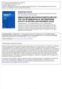
Figure 3. An example of a spreadsheet file for setting trap positions.
Proc. of SPIE Vol. 5514
Downloaded From: http://spiedigitallibrary.org/ on 04/15/2014 Terms of Use: http://spiedl.org/terms
139
5. RESULTS AND DISCUSSION Results were obtained for patterns of trapped objects being manipulated in to 2-D geometries and 3-D geometries (Figures 4, 5, 6 and 7). For all of the 3-D geometries, the traps were laterally offset by 20 µm from the zero order to limit the effects alias orders creating unwanted ghost traps. All holograms were generated at a size of 512x512 pixels, utilising the full resolution of the SLM. 5.1 Results Α simple 2-D square formed from four silica spheres is shown in Figure 4. This shows a simple 2-D trajectory sequence in a single plane, where the trap positions are controlled by the changes in the x- and y-axis coordinates specified in the spreadsheet.
Figure 4. Sequence of frames showing four 2 µm silica spheres forming a square with 10 µm side lengths, with the times at which each frame was taken shown in the bottom corner.
However, the main motivation of our research is to form 3-D structures of dielectric objects. Three such structures (Figure 4, 5 and 6) were formed from sequences of holograms (for example 2000 forming the sequence shown in Figure 5) displayed on the SLM at a rate of 10Hz. The first of these sequences shows the morphing of a cube from a line of eight silica spheres (Figure 5). This geometry was trapped to show that objects can be held directly above each other while in different planes, without the objects falling into the same trap.
Figure 5. Sequence of frames showing 2 µm eight silica spheres forming a cube with 6.5 µm side lengths. The elapsed time from the start of the sequence is shown in the bottom corner.
The next sequence shows a 3 plane geometry of trapped silica spheres (Figure 6). The top and bottom planes both have 3 silica spheres in the same positions forming a triangle and the two planes are separated by 12 µm . Between these two planes a further triangle, rotated by 180 degrees, prior to stacking is inserted. Again, this shows how well the GS algorithm efficiently assigns light spots axially above each other without the beads falling into the same trap.
140
Proc. of SPIE Vol. 5514
Downloaded From: http://spiedigitallibrary.org/ on 04/15/2014 Terms of Use: http://spiedl.org/terms
Figure 6. Sequence of frames showing nine 2 µm silica spheres forming 3 triangles with 5 µm side lengths and a 6 µm spacing between the planes. Note the central triangle is rotated by 60 degrees. The times at which each frame was taken is shown in the top corner.
The final sequence of video frames shows an arrangement with a greater number of trapped spheres (eighteen in total), in the geometry of two grids of 9 spheres axially above each other (Figure 7). Such geometries of spheres are difficult to trap by filling the traps from a static hologram. By semi-automating the morphing process, the user only has to trap objects in the initial geometry and then initialise the hologram sequence.
Figure 7. Sequence of frames showing eighteen 1 µm silica spheres initially trapped in two lines of nine spheres and morphed to form two grids of 3 by 3 in different planes. The times at which each frame was taken is shown in the top corner.
5.2 Discussion We have shown several examples of particles manipulated into 2-D and 3-D geometries from an initial 2-D array. An automated process of hologram design, in which the user controls the speed at which the holograms are generated and displayed in the SLM, carries out the manipulation of trapped particles. Previously, manipulation of trapped particles was carried out by reconfiguring holograms by changing the position of traps with cursor/mouse control or keyboard inputs 9, and by pre-calculating holograms and displaying them in the SLM at a given rate 5. The method we have used
Proc. of SPIE Vol. 5514
Downloaded From: http://spiedigitallibrary.org/ on 04/15/2014 Terms of Use: http://spiedl.org/terms
141
to calculate the hologram designs and display them in the SLM greatly reduces the time to generate a hologram sequence for manipulation of particles in HOTs. As mentioned earlier, the motivation behind our work is to create 3-D geometries of trapped objects. The 3-D geometries created so far range in volume from thousands of µm 3 to several mm3, with between 8 and 18 trapped objects. Potentially larger 3-D geometries, several mm3 in size and with more planes, could be trapped, extending previous large 2-D geometries 4, 10. The limiting factors in forming large geometries of trapped objects is not the hologram design, but the special resolution of SLMs 5 and the laser power. Previously, we have demonstrated the ability to make such structures permanent, by setting them in gel 11.
6. CONCLUSIONS We have shown that patterns of trapped objects can be manipulated in to either 2- or 3-D geometries. These include trapping objects above each other in different axial planes, with sequences of holograms calculated in real-time using our modified Gerchberg-Saxton algorithm. The benefits of calculating such hologram sequences are reduction in time to calculated the holograms and the operator only loads the traps in their initial geometry. Holograms designed in this manner will have uses in the areas of photonic crystals, seeding crystal growth, permanent 3-D structures, the creation of pumps, valves and particle control within microfluidic devices, measuring the mechanical properties of materials and biological studies.
6. REFERENCES 1. A. Ashkin, J. M. Dziedzic, J. E. Bjorkman and S. Chu , " Observation of a single-beam gradient force optical trap for dielectric particles , " Opt. Lett. 11, 288-290, (1986). 2. J. E. Molloy and M. J. Padgett , " Lights, action: optical tweezers , " Contemp. Phys. 43, 241-258 (2002). 3. D. G. Grier , " A revolution in optical manipulation , " Nature, 424, 810-816 (2003). 4. J. E. Curtis, B. A. Koss and D. G. Grier , " Dynamic holographic optical tweezers , " Opt. Commun. 207, 169-175 (2002). 5. G. Sinclair, J. Leach, P. Jordan, G. Gibson, E. Yao, Z. J. Laczik, M. J. Padgett and J. Courtial , " Interactive application in holographic optical tweezers of a multi-plane Gerchberg-Saxton algorithm for three-dimensional light shaping , " Opt. Exp. 12, 1165-1670 (2004). 6. R. W. Gerchberg and W. O. Saxton , " A practical algorithm for the determination of the from image and diffraction plane pictures , " Optik 35, 237-246 (1972). 7. T. Haist, M. Schönleber and H. J. Tiziani , " Computer-generated holograms from 3D-objects written on twistednematic liquid crystal displays , " Opt. Commun. 140, 299-308 (1997). 8. V. Soifer, V. Kotlyar and L. Doskolovich, Iterative Methods for Diffractive Optical Elements Computation (Taylor & Franicis Ltd., London, 1997). 9. J. Liessener, M. Reicherter, T. Haist and H. J. Tiziani , " Multi-functional optical tweezers using computergenerated holograms , " Opt. Commun. 185, 77-82 (2000). 10. J. P. Hoogenboom, D. L. J. Vossen, C. Faivre-Moskalenko, M. Dogterom and A. van Blaaderan , " Patterning surface with colloidal particles using optical tweezers , " Appl. Phys. Lett. 80, 4828-4830 (2002). 11. P. Jordan, H. Clare, L. Flendrig, J. Leach, J. Cooper and M. Padgett , " Permanent 3D structures in a polymeric host created using holographic optical tweezers , " J. Mod. Opt. 51, 627-632 (2004).
142
Proc. of SPIE Vol. 5514
Downloaded From: http://spiedigitallibrary.org/ on 04/15/2014 Terms of Use: http://spiedl.org/terms