generative macro process planning system has been developed and is reported ... master template of a composite part, lend themselves to RMS predicated on a.
SEMI-GENERATIVE MACRO-PROCESS PLANNING FOR RECONFIGURABLE MANUFACTURING Ahmed Azab, Giulio Perusi, Hoda ElMaraghy† and Jill Urbanic Intelligent Manufacturing Systems (IMS) Centre, University of Windsor {azab, perusi, hae, urbanic}@uwindsor.ca
Global competition and frequent market changes are challenges facing manufacturing enterprises at present. Manufacturers are faced with new unpredicted modifications at the part design level, which require increased functionality at the system design level. Reconfigurable Manufacturing Systems (RMS) addresses this situation by providing the exact capacity needed when needed. Process planning concepts and methods should be developed to support this new manufacturing environment. Variant process planning systems with their rigid definition of the boundaries of part families do not satisfactorily support Reconfigurable Manufacturing Systems. A semigenerative macro process planning system has been developed and is reported in this paper. Precedence graphs, which depict the precedence relationships between features/operations, are reconfigured by adding and removing nodes. The problem of generating optimal macro-level process plans is combinatorial in nature and proven NP-hard. Hence, a random-based heuristic based on Simulated Annealing is tailored for this problem. Finally, a realistic case study is presented to illustrate the proposed methodology. A family of single-cylinder front covers is used. The proposed method produced good quality optimal solutions and is proven efficient in terms of computation time as demonstrated by the obtained results.
1. INTRODUCTION Mass customization and agile manufacturing are paradigms that have emerged quite recently to face the new challenges of the twenty-first century. Manufacturers are faced day after day with varying product mixes. They are required to machine parts, which are not strictly defined within the boundaries of their respective families of parts. Considerations of product variety and new product introductions at the fundamental design stage for a dedicated manufacturing system are ignored. A Flexible Manufacturing System (FMS) on the other hand overcomes this challenge by having all the needed functionality built-in from day one; however this results in high initial capital investments as well as relatively lower utilization. In order to stay competitive, new types of manufacturing systems that are more responsive must be developed (ElMaraghy, 2006). Reconfigurability, an engineering technology that †
Corresponding author.
2
Digital Enterprise Technology
deals with cost-effective, quick reaction to market changes, is needed (Koren et al., 1999). Reconfigurable Manufacturing Systems (RMS) is created by incorporating basic process modules that can be rearranged or replaced quickly and reliably (Mehrabi et al., 2000). Proccess planning has two distinguished levels, Macro- and Micro-level planning [ElMaraghy, 1993]. At the Macro-level, planning is concerned with identifying the main tasks and their best sequence and the type of manufacturing processes. Micro-level planning details process parameters, required tools and setups, process time and resources. Process planning can also be classified into variant and generative. Retrieval-based process planning techniques, based on a master template of a composite part, lend themselves to RMS predicated on a defined part family. However, this approach results in less than optimum process plans because of the lack of specificity, precision, refinement and optimization possible at this high level of abstraction. Generative process planning is better able to handle products variety by generating process plans from scratch using rule- and knowledge-based systems, heuristics and problem specific algorithms. Pure generic generative systems are not yet a reality. Hence, a practical macro-level system, which is variant in nature, but yet also able to generate process plans for new parts that are not members of the original part family’s master plan, is proposed for RMS. Hetem (2003) discussed research, development and deployment of concepts and technologies to develop variant process planning systems for RMS. Bley and Zenner (2005) proposed another variant concept - an integrated management concept that allows meeting requirements of different markets and changing needs by generating a generalized product model. Both papers presented a strictly retrieval type system, which did not support introduction of new features into the part family caused by changing demands. There is a dearth of literature that offers generative process planning solutions for RMS. The following papers implemented simulated annealing in process planning. Lee et al. (2001) proposed four simulated annealing algorithms to solve the operation sequencing problem. Ma et al. (2000) reported a simulated annealing algorithm for operations selection and sequencing. Li et al. (2002) developed a hybrid genetic algorithm-simulated annealing approach to optimize process plans by concurrently considering machine assignment, selection of setup plans and sequencing. Brown et al. (1997) proposed a generative simulated annealing algorithm. Ma et al. (2002) presented the development of a computer-aided process planning (CAPP) system based on genetic algorithm and simulated annealing. In this paper, a heuristic based on simulated annealing, tailored to meet the need of hybrid process planning, generates optimal operation sequences for reconfigured parts with features beyond the pre-defined boundaries of the original part families.
2. METHODOLOGY 2.1 Knowledge Representation and Manipulation The basic input to process planning is the part CAD description including the part’s form features attributes, the working Geometric Dimensions and Tolerances (GD&T) and surface finish specifications. The large number of interactions that
Semi-Generative Process Planning for Reconfigurable Manufacturing
3
exists between the different form features constituting the part complicates the problem. A Feature Precedence Graph (FPG), which is a tree-like structure graph, is adopted where machining features are mapped onto nodes. Arcs between nodes represent features precedence. Each arc carries a cost, which approximates the number of tasks to be performed. The FPG is manipulated by adding and removing nodes to accommodate additional as well as missing machining features in the new parts. An FPG is translated into an Operations Precedence Graph (OPG), where each feature corresponds to one or more machining operation (Figure 2). 2.2 Developed Heuristic The objective is to sequence a global set of machining operations of a given part subject to a number of precedence constraints in order to minimize the total idle time spent mainly in repositioning the workpiece or fixture and tool changes. This problem has already been proven to be NP-hard. Hence, a search heuristic based on Simulated Annealing is developed. Simulated Annealing is a hill-climbing search method suitable for solving combinatorial problems as well as continuous problems with multi-modal objective functions (Vidal, 1993). The proposed algorithm is comprised of two nested loops, an outer loop where the annealing temperature (T) decreases and an inner one, which iterates a number of loops that decrease with T. In the inner loop new moves to neighboring solutions are accepted if they are of better quality to allow for hill climbing. Lower quality solutions are also accepted with an exponential probability distribution. An algorithm is developed to validate the generated relaxed sequences against the precedence constraints and, then as needed, repair them if no valid feasible solutions are generated after a certain number of moves. The reason behind this validation process is that the solution space before the application of the constraints is factorial in size. It is also believed that the size of this part of the solution space is exponential in nature, which renders the search infeasible after applying the constraints. Therefore, it would be inefficient to wait until a feasible solution is generated randomly since the probability of its generation proved to be very low. Therefore, a shuffling operator is applied at the end of each outer loop to increase the chances of exploring more parts of the feasible solution space. The best solution found is always stored and updated.
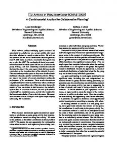
3. CASE STUDY 3.1 The Front Cover Part Family A single cylinder, air cooled, overhead valve engine front cover family of parts is used as an example to demonstrate the developed method. The aluminum front covers are die cast to the near net shape; finish machining is required for precision features and the tapped holes. The family’s composite part is shown in Figure 1. A sample of features, their labels, corresponding operation information, the Tool Access Direction (TAD) and the number of each feature type are shown in Table 1. A three axis horizontal Reconfigurable Machine Tool (RMT) is assumed to be used; hence, three setups are required to produce the part in order to access the features on the front and back faces (-Z, +Z) and the side face (+X). The ratio of the time
4
Digital Enterprise Technology
required to position the workpiece on a different fixture (composed of unloading the workpiece, cleaning the setup, and loading the workpiece) to the tool changeover time is assumed 2:1. The FPG shown in Figure 2 can be easily translated to an OPG using the operations information found in Table 1. The type of precedence is shown on the FPG by having the arrows carry a symbol denoting its type. S stands for precedence due to fixture or setup datum points; and d for dimensional precedence. If it is a dimensioning datum constraint, the appropriate GD&T symbol is then used. Some feature labels in the FPG are suffixed by an r or f; this indicates that both roughing and finishing operations are required for these specific features. The precedence constraints that must be satisfied are: 1. The features must be accessible by the tool; 2. The logical sequence of operations; 3. The dimensional and geometrical precedences are considered; 4. The non-destructive constraint; 5. The precedence due to machined setup datum points; and 6. Good machining practice. The roughing and finishing operations may be separated by some other features to satisfy the non-destructive precedence. This constraint, for example, influences the feature precedence of features f2 and f3 on the cover. Table 1 - Features, operations, tools and TAD for the composite part Features f1 f2 f3 f4 f5 f6 f7 f8 f9 f10 f11 f12 f13 f14 f15 f16
Operation description Drilling Boring Finish boring Drilling Boring Finish boring Rough milling Finish milling Finish milling Rough boring Boring Finish boring Drilling Milling Drill’s spot face Tapping Tapping Rough boring Boring Finish boring Drilling Tapping Drilling Drilling Finish milling Finish milling Drilling Boring Finish boring Drilling
Operations 1 2 3 4 5 6 7 8 9 10 11 12 13 14 15 16 17 18 19 20 21 22 23 24 25 26 27 28 29 30
Tool ID T1 T2 T3 T4 T2 T3 T5 T6 T6 T7 T8 T9 T4 T5 T10 T11 T12 T13 T14 T15 T1 T16 T1 T1 T6 T6 T4 T2 T3 T17
Tools Step drill Ø7mm Bore Ø7.5mm Bore Ø8mm Core drill Ø7mm Bore Ø7.5mm Bore Ø8mm End mill Face mill Face mill Special rough boring tool Special boring tool Special finish boring tool Core drill Ø7mm End mill Spot face and tap drill M20-1.5 tap M10-1.5 tap Bore Ø16.25mm Bore Ø17.25mm Bore Ø18mm Step drill Ø7mm Special 9/32 (inch) tap Step drill Ø7mm Step drill Ø7mm Face mill Face mill Core drill Ø7mm Bore Ø7.5mm Bore Ø8mm Special drill Ø4.5mm
TAD
# of features
z
2
-z
1
z
1
-z
1
z
1
z -z
8 1
x
1
-z
4
z
1
-z
6
z z -z z
1 1 1 1
-z
1
Semi-Generative Process Planning for Reconfigurable Manufacturing
5 ± 0.05
± 0.05
f9 (x 4)
f11 (x 6)
0.02 Z
f10
± 0.03
f6 (x 8)
f5
f7 f1 (x 2)
f8 Z 0.02
y
z
Z
y x f14
f16
f4
f3 f2
f12
f13
f15
x
Figure 1 - The composite cylinder front cover A new member of the front cover extended family, illustrated in Figure 3, is introduced. It contains 8 features in common with the existing composite part (highlighted in black in both Figures 1 and 3), but it also has 7 new features, which do not exist in the original part family’s composite part. Details of the features are shown in Table 2. The original three-axis horizontal configuration of the RMT is not sufficient for producing the new part; an extra dedicated setup or two special angle head tools would be required to machine feature f17, for example. Hence, the machine tool is reconfigured by adding an appropriate rotational axis of motion onto the spindle or table, i.e. the RMT becomes a 4-axis horizontal machining center.
Figure 2 - Feature precedence graph (FPG) of the original composite and the new cylinder front cover
z
6
Digital Enterprise Technology Table 2 - Features, operations, tools and TADs for the new cylinder front cover
Operation # of Operations Tool ID Tools TAD features description Drilling 1 T18 Drill Ø7mm f1 Boring 2 T19 Bore Ø7.5mm z 2 Finish boring 3 T20 Bore Ø8mm Drilling 4 T18 Drill Ø7mm Boring 5 T19 f2 Bore Ø7.5mm -z 1 Finish boring 6 T20 Bore Ø8mm Rough milling 7 T21 End mill f3 z 1 Finish milling 8 T22 Face mill f4 Finish milling 9 T22 Face mill -z 1 Rough boring 10 T23 Step drill Ø49mm f5 z 1 Boring 11 T24 Bore Ø51mm Finish boring 12 T25 Bore Ø52mm f6 Drilling 13 T18 Drill Ø7mm -z 8 Rough milling 14 T21 End mill f7 -z 1 Finish milling 15 T26 Face mill b Surface finish 16 T27 Spot face and tap drill ‡ f8 x 1 Tapping 17 T28 M18-1.5 tap Surface finish 31 T27 Spot face and tap drill f17 x‡ 1 Tapping 32 T28 M18-1.5 tap f18 Tapping 33 T29 Tap drill Ø7mm -z 8 Rough boring 34 T30 Bore Ø19mm Boring 35 T31 f19 Bore Ø20.5mm -z 1 Finish boring 36 T32 Bore Ø21.5mm Rough boring 37 T23 Step drill Ø49mm Boring 38 T24 f20 Bore Ø51mm z 1 Finish boring 39 T25 Bore Ø52mm Boring 40 T33 Bore Ø14mm Boring 41 T34 Bore Ø16mm f21 -z 1 Groove 42 T35 Special bore Ø5mm Finish milling 43 T26 Face mill b f22 Drilling 44 T18 Drill Ø7mm -z 1 f23 Milling 45 T21 End mill -z 1 ‡ f8 & f17 TAD is different; however reconfiguring the RMT, adding a 4th axis, eliminated this distinction. Features
± 0.05 ± 0.03 ± 0.05
0.02 W
f18 (x 8)
f19
f20
f5
f6 (x 8) f1 (x 2)
f7 W
f8
f17
y z
y
0.02 X
x
X
f21 f22 f23
f4
f3
f2
x
Figure 3 – Additional new part of the cylinder front cover family
z
Semi-Generative Process Planning for Reconfigurable Manufacturing
7
3.2 Results Ten runs were performed for each engine front cover, the composite as well as the additional new part of the front cover family. The best near optimal operation sequences are given in Tables 3-4. For the composite part, the mean and standard deviation of the objective function values are 32.4 and 0.52 respectively. As for the additional new part the mean and standard deviation are 40 and 0.94 respectively. It can be concluded from the close difference between the best objective function values obtained and the averages, and also the small values of the standard deviation that the results obtained were consistent and of very close quality. In many cases, even more than one solution is obtained with the same objective function value. The search algorithm parameters were tested to arrive at the best working ranges. Table 3- Results for the composite part
Near-optimal sequence of operations 24 1 2 3 10 11 12 13 26 16 27 28 29 4 30 5 21 22 14 17 6 9 25 7 18 8 15 19 23 20 1 2 3 23 24 10 11 12 13 26 4 27 28 29 30 21 17 9 15 22 25 14 5 6 16 18 19 7 20 8 1 23 2 3 24 10 11 12 13 15 26 16 18 19 20 7 8 27 25 21 9 17 28 4 22 5 6 29 30 14 1 24 2 3 10 23 11 12 13 26 4 27 28 5 17 21 6 29 25 16 22 9 7 30 14 15 18 19 8 20 15 16 1 2 3 10 11 12 13 24 26 23 25 9 21 27 22 17 14 4 5 6 7 18 19 20 8 28 29 30 1 2 3 10 11 12 13 23 26 27 28 29 30 17 9 25 21 22 14 4 15 16 5 6 7 8 18 19 24 20 O = Objective function value.
O
32
Table 4 - Results for the member part Near-optimal sequence of operations 1 2 3 7 10 11 12 37 38 39 34 9 14 45 35 4 33 5 15 40 8 41 42 6 43 36 13 44 31 32 16 17 1 2 3 10 11 12 7 37 38 39 9 34 14 35 36 33 15 40 41 8 4 13 45 5 6 42 43 44 31 16 17 32 1 2 3 10 11 12 37 38 7 39 34 45 14 4 33 15 40 5 41 6 42 35 31 16 17 36 43 13 44 32 9 8 O = Objective function value.
O 39
4. CONCLUDING REMARKS A practical semi-generative process planning approach suitable for the reconfiguration of both the products and manufacturing systems has been developed. The macro-level process plan is formulated as a sequence of operations corresponding to a set of features in the part. The interactions between the part’s different features/operations are modeled using Features/Operations Precedence Graphs (FPG/OPG). The FPG/OPG graphs of a part family’s composite part are edited to account for the missing as well as the added features. A random-based heuristic is developed to obtain optimal or near-optimal operation sequences. A validation scheme is developed and used to maintain the specified precedence relationships. An optimal single operations sequence can easily become less optimal in a changeable production environment; hence the importance of adapting to the changes and producing alternate optimal operations sequences for the changed parts becomes obvious. The proposed method is applied to an industrial example of single-cylinder family of front covers defined by a composite cover and a corresponding master process plan. A new macro-level process plan is generated for a new cover, the
8
Digital Enterprise Technology
features of which differ (new, missing and modified) from those that exist in the original family’s composite part. The manufacturing system machines had to be reconfigured accordingly to be capable of producing the new features in the introduced front cover. Although this re-planning is normally done off-line, the developed heuristic has the advantage of being fast (10 minutes on average per run on a Pentium 4 with 1 GB RAM); hence, multiple runs are possible to arrive at alternate solutions efficiently. Moreover, converting the code deployed on MATLAB™ (an interpreter) into an executable could further reduce the algorithm execution time. For future work, a hybrid heuristic with Genetic Algorithms may be developed to transform the point search into a population search, and hence more than one sub-optimal solution could be obtained from a single run.
5. REFERENCES 1. Bley, H and Zenner, C. Feature-based planning of reconfigurable manufacturing systems by a variant management approach. CIRP 3rd International Conference on Reconfigurable Manufacturing 2005. 2. Brown, KN and Cagan, J. Optimized process planning by generative simulated annealing. Artificial intelligence for engineering design, analysis and manufacturing 1997; 11 3: 219-235. 3. ElMaraghy, HA. Flexible and Reconfigurable Manufacturing Systems Paradigms, Special Issue of the International Journal of Manufacturing Systems (IJMS), In Press, 2006. 4. ElMaraghy, HA. Evolution and future perspectives of CAPP, CIRP Annals, 1993; V. 1, 42 2: 739-751. 5. Halevi, G and Weill, RD. Principles of process planning. Chapman & Hall, 1995. 6. Hetem, V. Variant process planning, a basis for reconfigurable manufacturing systems. CIRP 2nd International Conference on Reconfigurable Manufacturing 2003. 7. Koren, Y, Heisel, U, Jovane, F, Moriwaki, T, Pritschow, G, Ulsoy, G and Van Brussel, H. Reconfigurable manufacturing systems. CIRP Annals- Manufacturing Technology 1999; 48 2: 527-540. 8. Lee, D-O, Kiritsis, D and Xirouchakis, P. Search heuristics for operation sequencing in process planning. International journal of production research 2001; 39 16: 3771-3788. 9. Li, WD, Ong, SK and Nee, AYC. Hybrid genetic algorithm and simulated annealing approach for the optimization of process plans for prismatic parts. International journal of production research 2002; 40 8: 1899-1922. 10. Ma, GH, Zhang, YF and Nee AYC. A simulated annealing-based optimization algorithm for process planning. International journal of production research 2000; 38 12: 2671-2687. 11. Ma, GH, Zhang, YF and Nee AYC. An automated process planning system based on genetic algorithm and simulated annealing. Proceedings of the ASME Design Engineering Technical Conference 2002; 3: 57-63. 12. Mehrabi, MG, Ulsoy, AG and Koren Y. Reconfigurable manufacturing systems: key to future manufacturing. Journal of Intelligent Manufacturing 2000; 11 4: 403-19. 13. Vidal, R. Applied simulated annealing. Springer-Verlag, 1993.