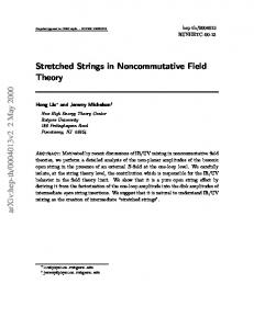
[11], and an expression for the elastic free-energy was derived by means of the Gaussian ... Experiments are performed in a thin-film geometry (see Fig. 1), and ...
Semi-soft elasticity and director reorientation in stretched sheets of nematic elastomers Sergio Conti and Antonio DeSimone Max Planck Institute for Mathematics in the Sciences, Inselstr. 22-26, 04103 Leipzig, Germany Georg Dolzmann Department of Mathematics, University of Maryland, College Park MD 20742, USA (Dated: August 2, 2002)
Abstract A two-dimensional effective model for the semi-soft elastic behavior of nematic elastomers is derived in the thin film limit. The model is used to investigate numerically the force-stretch curves, the deformed shape, and to resolve the local patterns in the director orientation in a stretching experiment. From the force-stretch curves we recover the two critical stretches which mark the transition from hard to soft and back to hard response. We present an analytical model for their dependence on the aspect ratio of the sample, and compare with numerical results. PACS numbers: 62.20.-x,61.30.-v,61.41.+e
1
I.
INTRODUCTION
Nematic elastomers combine the typical entropic elastic properties of cross-linked polymer networks with the orientational instabilities of liquid crystals [1–3, and references therein]. Besides their appeal as a model system, nematic elastomers have several potential applications, ranging from optical waveguides [4] to thermo-mechanical actuators [5] and artificial muscles [6]. Recent investigations have also focused on dynamical effects [7] and on alternative actuation mechanisms, such as UV light [8]. Stretching experiments on sheets of nematic elastomers have revealed semi-soft elastic response and formation of a characteristic striped pattern of the director orientation [9, 10]. Theoretically, the presence of an instability related to the coupling of elastic deformations to the alignment of the nematic director had been first predicted by Golubovi´c and Lubensky [11], and an expression for the elastic free-energy was derived by means of the Gaussian approximation by Bladon, Terentjev and Warner (BTW) [12]. The force versus stretch diagrams computed with this energy are ideally soft, in the sense that the force is zero up to a critical stretch. The typical experimentally observed behavior, however, is semi-soft. More precisely, three different response regimes emerge with increasing stretch: initially hard response without any movement of the director, then soft response accompanied by striped patterns in the director orientation field, and, finally, hard response with the director aligned along the direction of maximal stretch. This semi-soft behavior has been attributed to fluctuations in the director orientation at cross-linking by Verwey, Warner and Terentjev (VWT) [13]. They obtained a correction to the BTW energy and were able to reproduce, within a macroscopically affine approximation, the main features of the experimental observations. Their work focuses on uniform macroscopic deformation gradients and does not attempt to resolve the non-uniform structures present around the clamps in the typical experimental geometry (see Fig. 1), such as those observed by Zubarev et al. [14]. To derive the force versus stretch diagrams, VWT computed a formula for the effective energy corresponding to a macroscopic uniaxial deformation as a function of a scalar stretching parameter. The dependence of the effective energy density on the full strain tensor was not addressed. In this paper, we investigate the reorientation process as a function of position and applied stretch, including the inhomogeneities around the clamps, based upon a determination of the two-dimensional effective energy describing the macroscopic behavior of thin sheets. This
2
procedure yields a coarse-grained description of the system, with (energetically optimal) fine-scale oscillations correctly accounted for in the energetics, but averaged out in the kinematics. In Section II we formulate a reduced two-dimensional theory describing thin films of nematic elastomers, and in Section III we derive the corresponding macroscopic effective energy. Then we use in Section IV the effective energy to compute numerically (with finite elements) the local deformation, the director orientation, and the force transmitted by the sample in the standard experimental geometries. Combining the numerical results with an analytical model, we propose a formula for the critical stretch marking the transition from soft to hard mechanical response and a procedure to extract the values of the material parameters from force-stretch curves. A three-dimensional analysis, including numerical simulations, of the ideally soft BTW model was reported in [15–18].
II.
DIMENSIONAL REDUCTION
The free energy density derived by VWT can be written, after an affine change of coordinates in the reference configuration [19], as � ˆ ˆ, n ˆ |2 − β|Fˆ n ˆ 0 ) = |Fˆ |2 − α|Fˆ T n ˆ 0 |2 W VWT (F , n
(1)
ˆ is a unit vector ˆ , |Fˆ |2 = Fˆij Fˆij , n where Fˆ = ∇ˆ u is the gradient of the deformation field u ˆ 0 is a unit vector parallel to the average director at crossdenoting the nematic director, n linking. The hat is used to denote three-dimensional vectors and tensors. From now on ˆ 0 is a constant unit vector parallel to the y axis, in agreement with the we assume that n experimental configurations. The customary assumption of incompressibility is incorporated by requiring that the energy be infinite whenever det Fˆ �= 1. The parameter α (0 < α < 1) includes both the strength of the nematic ordering and the strength of the coupling to the elastic degrees of freedom, and has typically a value of order 0.5. The small parameter β accounts for the fluctuation of the director at cross-linking, and is typically of order 0.01 to � 0.2. For β = 0, W VWT reduces to the BTW ideally soft energy.
Experiments are performed in a thin-film geometry (see Fig. 1), and numerical investigations with the ideally soft BTW energy revealed no structure in the out-of-plane direction [16]. Since we are only interested in stretching experiments (and not in compression, where buckling can play a role) we assume that the director is in-plane and that the deformation 3
FIG. 1: Experimental geometry. The sample is a thin sheet (typically the thickness is less than 0.5mm, and the lateral dimensions are of the order of 10mm). The top figure represents the initial condition, where the orientation of the director is uniform and parallel to the y axis. Extension with rigid clamps (thicker lines) in direction x leads then to striped patterns in the orientation of the director. These patterns disappear again at large stretches (bottom figure).
is linear in z, ˆ (x, y, z) = (ux (x, y), uy (x, y), γ(x, y)z) . u
(2)
The incompressibility constraint gives γ = 1/ det ∇u, where ∇u is the 2 × 2 in-plane deformation gradient. For films thinner than the scale of variation of the in-plane determinant we can neglect z∇γ in computing the full deformation gradient. The VWT energy (1) gives then, in the thin-film limit, the expression W (F, n) = |F |2 +
1 − α|F T n|2 − β|F n0|2 , 2 det F
(3)
where F = ∇u. Minimizing over n we get W (F ) = λ21 + (1 − α)λ22 +
4
1 λ21 λ22
− β|F n0|2
(4)
where λ1 ≤ λ2 denote the singular values of the deformation gradient F , i.e., the eigenvalues of (F T F )1/2 . The rest of this paper is concerned with a detailed analysis of the variational problem
�
W (∇u)dxdy
minimize
(5)
which determines the deformation field u from the energy (4).
III.
EFFECTIVE ENERGY
The energy density (4) is not convex, and indeed the energy of affine deformations can be reduced by formation of fine structures. Aim of this section is a determination of the effective energy Weff , also called the quasiconvex envelope [20], which results from minimizing Eq. (4) over all possible fine structures with a given average. We first compute the minimum over specific microstructures, and then show that our result is optimal, in the sense that no other microstructure can deliver a lower energy. We start by writing the energy in the equivalent form W (F ) = (1 − β)λ21 (F ) + (1 − α − β)λ22 (F ) 1 2 + 2 + β|F n⊥ 0| λ1 (F )λ22(F )
(6)
where (x, y)⊥ = (−y, x), and where we have used the identities |F |2 = λ21 (F ) + λ22 (F ) = 2 ⊥ |F n0 |2 + |F n⊥ 0 | . The last two terms in (6) are convex. Indeed, |F n0 | is convex in F , and
(det F )−2 is convex in the determinant of F , and taking the determinant of a gradient vector field ∇u commutes with taking spatial averages [see our discussion after Eq. (16)]. We thus consider fine structures where only the first two terms in Eq. (6) are modified. At the level of deformation gradients, we replace F with the two gradients Fδ1,2 = F + δ1,2 a ⊗ n0
(7)
where δ1 < 0 < δ2 , (a ⊗ b)ij = ai bj , and a is a unit vector which solves a · F −1 n0 = 0. ⊥ The latter condition is equivalent to det Fδ = det F , and since |Fδ n⊥ 0 | = |F n0 | the last two
(convex) terms of (6) are unchanged by replacing F with Fδ . The fact that the difference Fδ1 − Fδ2 is a rank-one matrix guarantees that there exists a continuous v(x) whose gradient takes values Fδ1 and Fδ2 . Thus, the affine deformation u(x) = F x can be perturbed by 5
FIG. 2: Sketch of the function χ(t) as defined in Eq. (8). The sketch in the upper right corner indicates the corresponding pattern generated in the sample, which from an elastic viewpoint consists of alternating in-plane shears, with interfaces with normal n0 = ey .
superimposing fine-scale oscillations, according to �
x · n0 v(x) = F x + aχ ε
�
,
(8)
where χ(t) is a periodic function of period |δ1 | + |δ2|, with derivative δ1 < 0 for −δ2 < t < 0, and derivative δ2 > 0 for 0 < t < −δ1 (see Fig. 2). Here ε is a small parameter which represents the length-scale of the microstructure. We do not resolve this scale explicitly, since experiments show a clear separation between the microstructure size (ε � 1 ÷ 10µm) and the sample size (10 mm). Models which explicitly resolve these length scales, by including Frank-type energies, have been considered within simple geometries e.g. in [21–23]. Now we choose δ1,2 so that the average energy per unit area of the microstructure �
−W (∇v) =
|δ2 | |δ1 | W (Fδ1 ) + W (Fδ2 ) |δ1 | + |δ2 | |δ1 | + |δ2 |
(9)
is minimal. Since the product λ1 (Fδ )λ2 (Fδ ) = det Fδ does not depend on δ, the sum of the first two terms in (6) is minimal whenever they are equal. This happens when λ1,2 = µ1,2 , where µ1,2 = a±1/4 (det F )1/2 , 6
(10)
and α . 1−β
a=1−
(11)
In the following we shall eliminate α from all equations in favor of a, which gives a more direct characterization of the phase boundaries [24]. The values δ1,2 must therefore be the solutions of the equation |Fδ |2 = µ21 + µ22 , which is equivalent to the quadratic equation δ 2 + 2δa · F n0 + |F |2 − (µ21 + µ22 ) = 0 .
(12)
This equation has two real roots of opposite sign for |F |2 < µ21 + µ22 . We conclude that all deformation gradients which obey λ1 (F ) ≥ aλ2 (F ) are unstable towards formation of microstructure as above. We call the corresponding region in the space of deformation gradients the soft (S) phase, and the rest, where the energy cannot be lowered by laminates as in Eq. (8), the hard (H) phase. Our result is 2 Weff (F ) = g(λ2 (F ), det F ) + β|F n⊥ 0| ,
where g(s, d) =
(13)
⎧ ⎪ ⎨ d−2
+ (1 − β)(d2 /s2 + as2 ) in H,
⎪ ⎩ d−2
+ 2a1/2 (1 − β)d
(14)
in S.
As above, H represents all deformation gradients F such that det F ≥ aλ22 (F ), and S those where the opposite inequality holds. Equations (13-14) have been obtained by evaluating the energy (6) on the laminates constructed in Eqs. (7-12). We now show that this construction is optimal. To do this, we consider a generic perturbation u of a given affine deformation F x and show that its average energy density �
�
−W (∇u) ≥ −Weff (∇u) �
= −
(15)
g (λ2 (∇u), det ∇u) + β (n⊥ 0
2 �
· ∇)u
,
is at least Weff (F ). Since g is a convex function, as can be checked by verifying that the matrix of its second derivatives is positive semidefinite, we obtain from Jensen’s inequality [25] that (15) is greater than or equal to ��
�
�
g −λ2 (∇u), − det ∇u 7
�
+ β
−(n⊥ 0
2
· ∇)u
.
(16)
Now − det ∇u = det F by Gauss-Green’s formula, and since λ2 (F ) is convex in F we get,
again by Jensen, −λ2 (∇u) ≥ λ2 (−∇u) = λ2 (F ). Since g is increasing in its first argument, we conclude that
��
�
�
−Weff (∇u) ≥ Weff −∇u = Weff (F ) .
(17)
This shows that the construction of Eqs. (7-12) is optimal. Energy reduction by formation of stripe domains as shown in Fig. 2 is well known in the literature on nematic elastomers, at least for uniaxial deformations. The arguments in this section extend the construction to all deformation gradients, and prove optimality. It is interesting to observe that, even in this larger class of constructions, the lamination direction (i.e. the normal to the stripes in the reference configuration) remains n0 , whereas the widths of the stripes are no longer equal (since, in general, δ1 �= −δ2 ) [26].
IV.
RESULTS
We have solved numerically the minimization problem
Weff (∇u), subject to the bound-
ary conditions sketched in Fig. 1, where Weff is the effective energy of Eqs. (13-14). Our computations have been performed with a Matlab finite element toolbox developed by F. Alouges, based on linear elements on an unstructured triangulation of the domain, which was generated using the public-domain mesh generator Triangle by J. R. Shewchuk. Typical meshes ranged from a few hundred to a few thousand nodes, and they were refined close to the clamps and to the free edge. Figure 3 shows the transmitted force as a function of imposed stretch for different values of β and a typical aspect ratio AR = lx /ly = 3 [27]. For small β the response approaches the ideally soft behavior, which is characterized by zero force up to a threshold (called s2 below). For finite β the force-stretch diagram is Z-shaped, in agreement with experiment (see e.g. [1, 2]). The additional kink appearing at small stretches (called s1 below) marks the transition from an initially hard response to the intermediate semi-soft behavior, and is absent for β = 0. The effect of changing the anisotropy parameter a is shown in Fig. 4. Figure 5 shows the effect of sample geometry at fixed material parameters. To better elucidate the influence of the geometry on the response, we compare our results with the affine approximation, on which most previous theoretical analysis are based [1, 2, 4, 13]. This is obtained by neglecting the constraint exerted by the clamps against contractions in 8
FIG. 3: Force versus stretch at a = 0.5, AR = 3, β = 0.1, 0.05, 0.01, and 0.001 (from higher to lower curve). The dot marks the value obtained from Eq. (19). The inset shows a blow-up of the region around s2 for β = 0.01, and the two linear fits used to determine s2 . The dots in the blow-up mark the computed points.
direction y, and gives for the force the expression ⎧ ⎪ ⎪ ⎪ ⎪ ⎨ ⎪ ⎪ ⎪ ⎪ ⎩
2(1 − β)1/3 a1/3 (s − s−2 ) 2β(1 − β)1/3 a1/3 s
1 < s < saff 1 aff saff 1 < s < s2
2(1 − β)1/3 a1/3 [a(1 − β) + β]s −
√2 2 as
(18)
s > saff 2
−1/3 −1/2 and saff (1 − β)−1/3 . For large aspect ratios the importance where saff 1 = (1 − β) 2 = a
of the clamps decreases, and the numerical curves converge to the affine approximation (see Fig. 5). From the data it is also clear that the first critical stretch s1 has very little dependence on the aspect ratio AR (see inset of Fig. 5). We now investigate in more detail aff the dependence of s2 on the geometry. This is relevant since the formulas for saff 1 and s2
are often used to identify the values of the material parameters a and β from experiments. Thus a better understanding of the effect of AR on s2 will lead to a more accurate estimate of the material parameters, as suggested in [2]. 9
FIG. 4: Force versus stretch at β = 0.1, AR = 3, a = 0.8, 0.7, 0.6, 0.5, 0.4, and 0.3 (from higher to lower curve).
For simplicity we start from the ideally soft β = 0 case. In the explicit construction shown in Fig. 6 the deformation gradient ∇u takes only four different values, and all of them are in the zero set of Wβ=0 (F ) [Eq. (4), with β = 0]. This means that all of them have singular values a−1/3 and a1/6 ; in region A the eigenvector corresponding to the largest eigenvalue is ey , in C it is ex , whereas in B ± the orientation is determined from continuity of the deformation u along the interfaces. A straightforward computation [17] shows that the construction of Fig. 6 can be performed for stretches up to s02 = a−1/2 − where −1/2
1+a AR0 = 2
� AR0 −1/2 a −1 AR
⎛� � � ⎝�1 +
(19) ⎞
4a1/2 − 1⎠ . (1 + a1/2 )2
(20)
It follows that, for β = 0, the force transmitted for all stretches up to s02 is exactly zero. The numerical values of s02 are in good agreement with the values of s2 obtained numerically for 10
FIG. 5: Force versus stretch at a = 0.5, β = 0.1, AR = 0.5, 1.5, 3, 5, and 20 (from higher to lower curve). The dashed curve shows the affine approximation, which is appropriate for AR → ∞. The inset shows a blow-up of the region at small stretches (the computed points are marked by crosses).
very small β (see Fig. 3). For finite β, we superimpose the AR-dependent correction just derived on saff 2 [defined after Eq. (18)], and get the estimate s∗2 = a−1/2 (1 − β)−1/3 −
� AR0 −1/2 a −1 AR
(21)
for the critical stretch s2 . We now turn to the numerical validation of this approximation. Values of s2 are extracted from a finite set of stretch-force data points with a method analogous to the one used in [2] to get s2 from experimental data. Indeed, we select ranges of points to the left and to the right of the kink, and fit them with straight lines. The first coordinate of their intersection defines s2 . Small changes in the set of points used for this fitting give an estimate of the error intrinsic in this procedure, which is typically less than 0.05%. The results so obtained are in good agreement with the prediction of Eq. (21), but small systematic deviations are 11
FIG. 6: Ideally soft (β = 0) piecewise affine deformations including the effects of the clamps. The upper panel shows the reference configuration, the lower one the deformed configuration. The maximal stretch at zero strain is attained when the B ± regions touch the clamps (so that the A regions reduce to triangles). The figure has been drawn with AR = 3, a = 0.5.
still observable. We plot in the inset of Fig. 7 the deviation s2 − s∗2 . We observed that the dependence of such differences on a is approximately quadratic. In Fig. 7 we also plot the scaled quantities a2 (s2 − s∗2 ) as a function of aspect ratio. The resulting dependence can be well approximated by a2 (s2 − s∗2 ) �
0.014 . AR3/2
(22)
The figure shows that this fit is satisfactory for all a and β we explored up to inverse aspect ratios of order 1. In order to illustrate the use of the present results in reconstructing material parameters from experimental measurements, and to assess the relevance of the proposed method, we now give an example based on a numerical experiment. We choose a material with typical parameters a = 0.5, β = 0.1, and AR = 1.5 [27]. From the numerical force-stretch curve, 12
FIG. 7: Deviation of the numerically computed values of s2 from s∗2 as given in Eq. (21), scaled with a2 (dots), as a function of the inverse aspect ratio 1/AR. The curve is Eq. (22). The inset shows the unscaled values of s2 − s∗2 . The data points correspond to a = 0.4, 0.5, 0.6, and 0.7; β = 0.01 and 0.1.
as plotted in Fig. 5, we extract by fitting with straight lines ssim = 1.036 and ssim = 1.361. 1 2 aff From the affine approximation, i.e., by setting ssim 1,2 = s1,2 as after Eq. (18), one can then
estimate
�
β =1−
−3 (ssim 1 )
aff
� 0.101 , a
=
ssim 1 ssim 2
�2
� 0.579 .
(23)
This corresponds to the calculation done e.g. in [2] starting from experimental data. To improve the result, one should solve the nonlinear equation s2 (a) = ssim 2 , where s2 (a) is given by Eqs. (20-22). The numerical solution is a � 0.500. A simpler method is to first compute aff aff is the approximation obtained the correction ∆s2 = s2 (aaff )−saff 2 (a ) � −0.0986, where a
for a with the affine approximation [Eq. (23)], and then to compute a�
s21 � 0.52 . (s2 − ∆s2 )2 13
(24)
FIG. 8: Rotation angle in the center of the sample for a = 0.5 and β = 0.2, 0.1, 0.05, 0.01, 0.005 (lower to upper curve).
Iteration of the procedure leads in a few steps to a very good solution of the nonlinear problem. This shows that the proposed scheme can correct the 15% error in the identification of the material parameter a given by the simple affine scheme of Eq. (23). The correction remains significant for larger AR: for AR = 3 it is of 8%, for AR = 7 of 4%. The local orientation of the director has been measured in stretching experiments by X-ray scattering [10, 14, 22]. To compare our results with these observations, we have reconstructed the local orientation of the director from the computed deformation gradients. For gradients F = ∇u in phase H the eigenvector associated with the largest eigenvalue of F F T gives the desired orientation. Gradients in phase S can be decomposed uniquely into their two components as discussed in Section II, then for each component the direction is recovered as above. These directions can be identified through the angles they form with
14
FIG. 9: Rotation angle in various points along the axis of the sample for a = 0.5 and β = 0.01. The highest curve is the point at the center of the sample, at distance lx /2 from each clamp, i.e. the same as plotted in Fig. 8. The other curves correspond to the points at distance 3lx /8, lx /4, and lx /8 from one clamp, still along the axis of the sample, as displayed in Fig. 10. The dashed curve gives the theoretical prediction of Eq. (25), expressed in terms of s1 and s2 as determined in the text.
ey . By symmetry, these two angles differ only in the sign for points along the central axis of the sample, and we only plot the positive one. In Fig. 8 we plot the director orientation in the center of the sample as a function of the imposed stretch for different values of β. In Fig. 9 we fix one value of β and explore the director orientation in different points along the axis of the sample. The plots are compared with the theoretical expression �
s22 s21 sin θ = 2 1− 2 s2 − s21 s
�
2
which was derived in the affine approximation in [13, 22]. 15
,
(25)
FIG. 10: Direction of the stripes across the sample for a = 0.5, β = 0.1, AR = 3, at a typical stretch in the semi-soft range s = 1.3. The stripes are parallel to the x-axis in the reference configuration, the picture shows their orientation in the deformed configuration. The dots mark the points used for displaying the local director rotation in Fig. 9.
We observe a change in behavior for the lower curves (corresponding to points close to the clamps) for stretches slightly above the one where the director in the central point is fully reoriented (angle = 90o ). This is due to the sharp increase in stress transmitted following the passage of part of the sample from phase S to phase H. Figure 10 reports the expected direction of the stripes across the sample, as should be seen in optical experiments. They are mostly parallel to the x axis, except for the regions around the clamps. Figure 11 shows the sample profiles at different stretches. For stretches larger than s2 the curvature of the free edge is much more localized in nematic elastomers than in more conventional rubbers, as shown by the comparison with a neo-Hookean material (an incompressible material with the isotropic, convex energy density W (F ) = |F |2 ). In the figure we also compare with results from three-dimensional simulations performed with β = 0, but with the addition of a small neo-Hookean regularization, which had given the same picture at large stretches.
V.
CONCLUSIONS
We have investigated the behavior of thin sheets of nematic elastomers in stretching experiments, through a combination of analytical and numerical techniques. Our method identifies an effective energy, which only depends on the average in-plane deformation gradient. The effective energy results from an instability towards formation of fine-scale oscillations, 16
FIG. 11: Sample profile (full curves) at various stretches for β = 0.01 and a = 0.5, compared with the corresponding result for a neo-Hookean material (dotted curves) and with the results obtained with three-dimensional simulations with β = 0 and a neo-Hookean regularization in [16] (dashed curves).
for deformation gradients in part of the phase space, leading to two distinct macroscopic modes of response, called soft and hard. In the soft response mode stripe domains, corresponding to small-scale oscillations in the director orientation, are expected. We identify all possible stripe patterns and show that no other small-scale structure can further reduce the energy. Numerical simulations, based on the effective energy, give accurate estimates of forcestretch characteristics, sample profiles and spatially-resolved director rotation. Our results lead to a method for an accurate identification of material parameters from experimental force-stretch curves. This procedure has been demonstrated with a concrete example. 17
Acknowledgments
We thank Fran¸cois Alouges for providing us with his Matlab finite-element toolbox. Most of this research was done while G. Dolzmann was visiting the Max Planck Institute for Mathematics in the Sciences. The support by the Max Planck Society and partial support by the NSF through grant DMS0104118 are gratefully acknowledged.
[1] E. M. Terentjev, J. Phys.: Condens. Matter 11, R239 (1999). [2] M. Warner, J. Mech. Phys. Sol. 47, 1355 (1999). [3] T. C. Lubensky, R. Mukhopadhyay, L. Radzihovsky, and X. Xing, Phys. Rev. E 66, 011702 (2002). [4] M. Warner and E. M. Terentjev, Prog. Polym. Sci. 21, 853 (1996). [5] A. R. Tajbakhsh and E. M. Terentjev, Eur. Phys. J. E 6, 181 (2001). [6] M. H´ebert, R. Kant, and P.-G. de Gennes, J. Phys. I France 7, 909 (1997). [7] S. M. Clarke, A. R. Tajbakhsh, E. M. Terentjev, and M. Warner, Phys. Rev. Lett. 86, 4044 (2001). [8] H. Finkelmann, E. Nishikawa, G. G. Pereira, and M. Warner, Phys. Rev. Lett. 87, 015501 (2001). [9] J. K¨ upfer and H. Finkelmann, Makromol. Chem. Rapid Comm. 12, 717 (1991). [10] J. Kundler and H. Finkelmann, Macromol. Rapid Comm. 16, 679 (1995). [11] L. Golubovi´c and T. C. Lubensky, Phys. Rev. Lett. 63, 1082 (1989). [12] P. Bladon, E. M. Terentjev, and M. Warner, Phys. Rev. E 47, R3838 (1993). [13] G. C. Verwey, M. Warner, and E. M. Terentjev, J. Phys. II France 6, 1273 (1996). [14] E. R. Zubarev, S. A. Kuptsov, T. I. Yuranova, R. V. Talroze, and H. Finkelmann, Liquid crystals 26, 1531 (1999). [15] A. DeSimone and G. Dolzmann, Arch. Rat. Mech. Anal. 161, 181 (2002). [16] S. Conti, A. DeSimone, and G. Dolzmann, J. Mech. Phys. Solids 50, 1431 (2002). [17] S. Conti, A. DeSimone, G. Dolzmann, S. M¨ uller, and F. Otto, in Trends in Nonlinear Analysis, edited by M. Kirkilionis, S. Kr¨ omker, R. Rannacher, and F. Tomi (Springer, Heidelberg, 2002). ˇ [18] M. Silhav´ y, manuscript (2001).
18
[19] We write Fˆ = λb1/6 (Id + (b−1/2 − 1)n0 ⊗ n0 ), where b = 1 − α − β and λ is the deformation gradient as used by VWT. This corresponds to a change of variables in the reference configuration, which affects the definition of aspect ratio (see [27]). [20] S. M¨ uller, in Calculus of variations and geometric evolution problems, edited by F. Bethuel et al. (Springer, Berlin, 1999), Springer Lecture Notes in Math. 1713, pp. 85–210. [21] J. Weilepp and H. R. Brand, Europhys. Lett. 34, 495 (1996), see also ibid., 37, 495 and 499 (1997). [22] H. Finkelmann, I. Kundler, E. M. Terentjev, and M. Warner, J. Phys. II France 7, 1059 (1997). [23] E. Fried and V. Korchagin, Int. J. Sol. Stru. 39, 3451 (2002). [24] To compare our formulas with VWT [13], note that their r corresponds to our 1/a, and their λ1 to our s1 = (1 − β)−1/3 . [25] Jensen’s inequality states that if f is convex, then the average of f (u(x)) is greater than or equal to f (¯ u), where u ¯ is the average of u. [26] The normal cannot be changed from n0 , since in the optimality argument of Eqs. (15-17) the two components of the energy (13) could be treated separately. [27] We define AR as the ratio between the length of the sample in the x and in the y direction in the reference configuration. The initial configuration differs from the reference configuration by the uniaxial stretch mentioned in [19], so that the ratio between its x and y dimensions is (1 − α − β)1/2 AR = a1/2 (1 − β)1/2 AR.
19