2014 5th IEEE RAS & EMBS International Conference on Biomedical Robotics and Biomechatronics (BioRob) August 12-15, 2014. São Paulo, Brazil
Sensor Fusion to Control a Robotic Walker Based on Upper-Limbs Reaction Forces and Gait Kinematics Carlos A. Cifuentes, Camilo Rodriguez, Anselmo Frizera, and Teodiano Bastos 1.
Abstract— This work proposes the implementation and validation of a new sensor fusion strategy based on force sensors and LRF (Laser Range Finder) to control a robotic walker. This approach combines user information about forearm reaction forces and gait kinematics from the legs scanning localization, to develop a more natural, safer and adaptable human-walker interaction. The work was carried out in four phases. First, a robotic walker platform was developed and the sensor subsystems were integrated. Second, a sensor fusion strategy to obtain the control parameters are defined. Third, the control strategy is presented. Finally, an experimental study to evaluate the sensor architecture and control was developed. One of the advantages of the humanwalker interaction here proposed is the computational efficiency. The sensor processing algorithms and the control strategy are executed in real-time, showing stable performance with human speed changes.
I. INTRODUCTION The world's population over 60 years old will more than triple from 600 million to 2 billion between the years 2000 to 2050 [1]. The majority of this increase is occurring in less developed countries where this group will rise from 400 million in the year 2000 to 1.7 billion by the year 2050 [1]. In Brazil, the number of people over 60 years old will reach 58 million in 2050 [2]. While these figures are not new and have been in the public domain for a while, it presents a huge challenge affecting public health policies. Human capacities in mobility decrease gradually with age as a consequence of neurological, muscular and/or osteoarticular deterioration. These factors produce kinematic changes on the gait patterns, including slower velocity and decreased stride and step length with increased stride frequency [3]. Disordered gait, defined as a gait that is slowed, aesthetically abnormal, or both, is not necessarily an inevitable consequence of aging but rather a reflection of the increased prevalence and severity of associated diseases [4]. Common diagnosis among people over 60 years old also include cardiovascular conditions, dementia, diabetes, arthritis, osteoporosis, and stroke [3].
This work was supported in part by CAPES, Brazil. C. A. Cifuentes, C. Rodriguez, A. Frizera and T. Bastos is with Electrical Engineering Department at the Universidade Federal do Espírito Santo (UFES), Vitoria, ES, 29075-910, Brazil (e-mail:
[email protected];
[email protected];
[email protected];
[email protected]).
978-1-4799-3128-6/6/14/$31.00 ©2014 IEEE
In the same manner, these conditions all have the potential to impact the human mobility. Thus, there is a significant need to improve the ability for older adults to have safe and efficient ambulation, as this may help to reduce the incident of fall and fractures. That way, some studies have shown that walking programs with a frequency of at least 3 to 5 times per week have been found to increase walking endurance and distance [5]. In this context, assistive devices reduce load on a painful joint and increase stability to empower the user's locomotion. Accordingly, conventional walkers are important examples of assistive devices because of its structural simplicity, low cost and rehabilitation potential. Walkers increase static and dynamic stability and also provide partial body weight support during functional tasks [6]. Nevertheless, conventional walkers may not provide sufficient support and stability for a safe locomotion. Propulsion and restraining forces necessary for forward progression may also be an inconvenience. However, the incorporation of motors to control the walker's motion and the development of control strategies that interpret the user's commands may allow safer human-walker mobility. Stability issues are dealt with special security mechanisms to prevent falls and undesirable movement intentions from the user [7]. II. BACKGROUND During the normal gait, the HAT (Head, Arms and Trunk) is considered to travel as a unit; it moves with the body's center of gravity and also transmits the walking direction to the lower limbs [8]. As a consequence of this, a direct sensing of the HAT orientation is suitable to get the user's walking direction to guide the robotic walker. The HAT orientation can be measured from interaction between upper-limbs and walker, which produces forces related to the user’s partial body weight support. Some approaches consider force sensors installed into the forearm supports. Usually, one 3D force sensor [9] or two [10] are integrated into the forearm support platform. This integration presents a more natural way to command the walker motion without previous training. In our previous works [10]-[12], the components of upper limb reaction forces during the walker-assisted gait were identified and characterized. These approaches presented preliminary human-walker trials performed without traction or controlled motion, which were useful to detect the presence of noise or elucidate undesired components that could affect the control strategy.
1098
In [11], a study showed that vertical components of forces are highly correlated with gait phases. Two main components were identified in each force signal: a continuous signal related to the user’s partial body weight unloading and a periodical component related to the gait cadence. A methodology to extract user's navigation commands related to components from upper-body force interaction data was presented in [10] and [12]. A low-pass filter is used to eliminate the frequency components introduced by ground-wheel interaction and an adaptive notch filter was implemented to reject the force interaction components caused by the user’s trunk motion during the gait. These components are present due to the natural trunk oscillations caused by the alternated supports and does not reflect the desired navigation commands. These filters are adjusted with a online estimation of the gait cadence, two alternatives were evaluated as following. In [12], a combination of the vertical force components of each arm is used for continuous estimation of the gait cadence. This architecture was evaluated with healthy subjects, and provided a high rate of cancelation of trunk components.
III. MATERIAL AND METHODS The approach presented in this work is focused on developing a sensor fusion strategy to achieve a more natural, safer and adaptable human-walker interaction. The work was carried out in four phases. First, a robotic walker platform was developed and the sensor subsystems were integrated. Second, a sensor fusion strategy to obtain the parameters controls is defined. Third, the control implementation is presented. Finally, a experimental study to evaluated the sensor architecture and control was developed. A. Robotic Walker Platform This section discusses the hardware and software components of the robotic platform named as UFES Smart Walker (Fig.1a). The developed robotic platform consists of a pair of differential rear wheels driven by DC motors and a front caster wheel.
Due to the fact that subjects with gait disorders present asymmetric gait patterns, it is not possible to obtain a robust cadence estimation from only a combination of the vertical force components of each arm. Thus, cadence estimation directly from the user's legs position was presented in [10], using ultrasonic sensors. A high rate of cancelation of trunk components for patients with disabilities was obtained, but the main disadvantage of this approach is that the user had to wear sensors on each leg compromising the usability of the device. Additionally, previous approaches do not take into account the gait kinematics as a control parameter. As aforementioned, kinematic changes on the gait patterns are common with age, and it is fundamental to safely apply control strategies to drive the robotic walker to be used by older people. Furthermore, it is interesting to continuously monitor gait parameters to follow up certain to pathologies and study the rehabilitation processes. This work proposes implementing and validating a new sensors fusion strategy based on force sensors and LRF (Laser Range Finder) to control a robotic walker. The LRF device provides fast integration with the electronic platform through serial communication and a contactless solution for the user. The approach here presented combines user information by means of forearm reaction forces and gait kinematics from the legs scanning in order to develop a more natural, safer and more adaptable human-walker interaction. This work is organized as follows. Section III describes the methodology of this work, where the robotic walker platform, sensor fusion architecture, and control implementation are presented. Section IV shows the experimental results of the human-walker controller, as well as the discussion. Finally, conclusions and future works are presented in Section V.
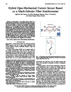
Figure 1. Robotic walker configuration. (a) UFES Smart Walker. (b) Description of the legs' localization detection.
An embedded computer based on the PC/104-Plus performs control and processing tasks. It is based on a 1.67 GHz Atom N450, 2 GB of flash memory (hard disk) and 2 GB of RAM. The application is integrated into a real-time architecture (Matlab Real-Time xPC Target Toolbox). The sensor configuration includes: One LRF sensor model URG-04LX from Hokuyo, which is mounted on the walker at the legs height. It is used to detect the legs localization through the Legs Detection Module (Fig. 1b), which is implemented on a processing board based on the dsPIC33F microcontroller. It is linked to the embedded computer via serial interface (RS232) and provides the leg's localization of every 100 ms.
1099
Two triaxial force sensors model MTA400 from Futek with their respective amplifiers CSG110, are installed under each forearm supporting platform (Fig. 1a). The force signals acquisition is done through a acquisition module with 16-bit resolution
with a sample time of 1 ms. The use of such sensors allow a complete study and modeling of the usermachine physical interaction that will be addressed in other experiments beyond the scope of this paper. The legs' localization is calculated in polar coordinates (Fig. 1b). The general process is based on the differences between two transitions events that define a leg pattern (xmarks on Fig. 1b). After that, both distance and angle measurements are calculated in relation to the middle point of each leg. In Fig 1b, ( d1 , a1 ) and ( d 2 , a 2 ), respectively, represent the polar coordinates of the left and right legs' localization. B. Sensor Fusion Architecture This work combines measurements from the upper-limbs reaction forces and the legs' localization to get the walker control parameters. Such parameters represent the link between the user and the walker in the control strategy. The method to obtain the parameters of the proposed model is presented in Fig. 2 and described as follows:
Figure 2. Model of sensor integration to control the robotic walker.
1)
d is measured directly using the LRF sensor after the legs'
localization
process
is
performed
d (d1 d 2) / 2 (Fig. 1b). Another measurement
used is the LDD (Legs Difference Distance), which is defined as the difference between the left and right legs ( d d1 d 2 ) (Fig. 1b). It is used for the computation of the human linear velocity ( vh ) and also to adjust the adaptive filters. 2) The human linear velocity ( vh ) is obtained through the product of gait cadence (LDD frequency estimation) and the gait step amplitude (LDD amplitude estimation) which are obtained after the legs' localization process. 3) Fl and Fr are the force components that include the intentions to guide the walker. These signals are obtained after an adaptive filtering process from upperlimb reaction forces. This filter is adjusted with a online estimation of the gait cadence (LDD frequency estimation). The human gait can be modeled as a Fourier
representation due to its periodic nature. FLC (Fourier Linear Combiner) and WFLC (Weighted-Frequency Fourier Linear Combiner) [13] are applied to the human gait in order to estimate gait related components and perform the filtering of the control parameters, as shown in Fig 3.
Figure 3. Sensor fusion strategy to get the control parameters.
FLC estimates both the amplitude and phase of quasiperiodical signals with a known frequency. It operates by adaptively estimating the Fourier coefficients of the model according to the least-mean-square (LMS) algorithm [13]. This is a descend method based on a special estimate of the gradient, which ensure inherent zero phase. FLC is useful for walking cadence estimation and also for cancelling the force components caused by trunk oscillations during the gait. The gait cadence can be defined as the rhythm of a person’s walk, usually expressed in steps per minute [14]. The frequency of the LDD signal is estimated to yield the gait cadence, and the method used is shown in Fig. 3. In which a WFLC (Weighted-Frequency Fourier Linear Combiner) algorithm was implemented for the gait cadence estimation. It is important to perform a previous stage of filtering (compatible with gait cadence frequencies) in order to a robust adaption to the values of gait cadence and the correct performance of the WFLC [11]. Experimentally, the LDD signal has a cadence according to a main frequency component, and a high-pass filter (Fig. 3) rejects static values (dc component) when the user is not walking, as these events affect the estimation performance. The human linear velocity ( vh ) can be defined as the product between the gait cadence and the step length [14] and, based on this, the amplitude of the LDD signal is estimated. As found on the literature [15], the WFLC algorithm can be used to robustly estimate the frequency of the input signal, and feed this information to the FLC algorithm that can robustly estimate the amplitude. In this work, the FLC algorithm was implemented in order to get a robust estimation of the step length. In Fig 3, according to the force intentions filtering architecture, a high-frequency component is related to vibrations introduced by both irregularities on the ground and imperfections on the surface of the walker’s wheels. For the cancelation of these components, a Butterworth low-pass filter, with cutoff frequency of 3Hz and order 2, was used.
1100
Finally, an on-line adaptive scheme to estimate and cancel the cadence components on a force signal Fi is shown, which is based on a WFLC module to detect the gait cadence (the same module used to estimated vh ). The FLC module estimates and subtracts the cadence related component on the Fi signal.
distance. Therefore, the inverse kinematics controller is ~ vw vh kd , where k is a positive gain to be adjusted. Finally, the control structure here proposed is shown in Fig. 5, on the one hand, from kinematics control, the control error is
~ d , the input controlled is vh , and vw is the action
control, On the other hand, from the fuzzy control, the inputs controlled are Fl and Fr , and the control action is w .
C. Control Implementation As aforementioned, the upper-limbs reaction forces are suitable inputs to guide the orientation of the robotic walker. y and z force components from right and left sensors are filtered individually using the filtering architecture previously presented (Fig. 3). From Fig. 4a, Fly and Fry present proportional values to the movement intention. These components were divided by the z-components ( Flz and
Frz ) in order to obtain force signals ( Fl and Fr ) that are also proportional to the amount of the body weight applied on each armrest. This feature is important in cases of asymmetrical support caused by a unilateral affection on the gait. These filtered forces are used in this approach to drive the walker angular velocity ( w ) through a classifier and controller based on fuzzy logic (Fig. 4a). More details about this fuzzy control implementation to guide the robotic walker can be seen in [10].
Figure 5. Block diagram of the proposed controller.
D. Experimental Study Two different experiments were conducted to evaluated the sensor and the control architecture. A volunteer without any dysfunctions associated with the gait was chosen to perform the experiments. In the first one, trials were performed without applying any control strategy to the walker's motors. The user was asked to performed a straight path of 10 m of length guiding the walker. The instruction provided to the user was performed in two different velocities. A metronome set the pace of the gait. Furthermore, steps of 0.5 m were marked with tape on the ground, to help the user to keep a constant step length. Finally, a experiment was conducted with the proposed control strategy in order to evaluated its effectiveness. The user was asked to performed u-shaped path using the robotic walker with normal speed.
Figure 4. Control implementation. (a) human-walker model to obtain
w . (b) human-walker model to obtain vw .
IV. RESULTS
One important improvement of this approach is to include the human kinematics changes into the controller such aforementioned. Thus, in Fig. 4b can be observed the strategy to control walker linear velocity ( vw ). The variable to be controlled is the human-walker distance d . The control objective is to achieve a desired human-walker distance dd to converge asymptotically to zero. This also reaches to improve the human-walker physical interaction. ~ The expression d vh vw shows the basic direct
~
kinematics of the walker, where d d dd (Fig. 4b) is the difference between the desired and the measured
In the first experiment, the human linear velocity extraction algorithm along with force's filtering strategy are presented. As a representative case of the obtained results, Fig. 6 shows the results of an experiment done with two different velocities. In this case, the human's speed is changed from 0.5 m/s back to 0.3 m/s. In Fig 6a, the distances read by the legs' localization module are shown (right and left leg in black and grey, respectively). In Fig 6b, the LDD signal is shown, which represents the input for WFLC and FLC algorithms. As a product between the gait cadence (Fig. 6c) and the gait amplitude (Fig. 6d) the human linear velocity (Fig. 6e) is obtained. Finally, as a example of the filter strategy, Fig. 6f
1101
and Fig. 6g, respectively, represent the y-axis and z-axis force components obtained from the left force sensor. The raw force signal, the force signal after the low pass filter and the force signal with cadence component rejected in each figure are depicted.
high forces yields by the body weight uploading The gait transitions can be observed in all the graphs, with the amplitude kept constant. The period of the sinusoidal function LDD describes the human linear velocity. Such as designed for this sensor fusion strategy, the gait cadence, human linear velocity and cadence rejection on the force signals reach stable values in approximately 3 seconds. Fig. 7 shows snapshots of instants of the experiment. It is noteworthy that the u-shaped path is analyzed in four phases: first, a first straight path (Fig. 7a); second, a first curve turning to the left (Fig. 7b); third, a second curve turning to the left (Fig. 7c); Finally, a last straight path (Fig. 7d).
Figure 7. Snapshot performing an U-shaped path by the user with the proposed control strategy.
Fig. 8 shows the control data recorded from the experiment during 50 seconds. In Fig. 8a, it is possible to observe lower values for the y-axis components when the subject is walking on a straight path (from 0 to 18s and from 30 to 50 s).. These intervals did not yield control actions on w (Fig. 8b). In Fig. 8a, the two left curves can be observed after the 18th and 25th second. A positive peak on Fly and a negative Figure 6. Sensors data of the experiment with speed variation from 0.5 m/s to 0.3 m/s. (a) Leg localization detection from LRF. (b) LDD signal. (c) Gait cadence estimation. (d) Gait amplitude estimation. (e) Human linear velocity. (f) Forces on the left forearm (y-axis). (g) Forces on the left forearm (z-axis).
The estimation algorithm shows a tendency to keep constant the distance between the walker and the legs which is used by the control strategy. As a matter of fact, the LDD signal oscillates around 0 m. This indicates that LDD is suitable as input for the WFLC and FLC algorithms. The cadence estimation has an adaptive behavior as it can be seen when the user reduces the walking speed from around one step per second in the first section, to approximately of 60% step per second. The amplitude is effectively kept close to 0.5 m, as expected. Finally, the human linear velocity is around 0.5 m/s initially and 0.3 m/s in the last part of the experiment. Despite low forces performed on the y-axis when a straight path is performed, the rejection of the cadence components on the force signals can be observed. However, the filtering effect is more evident on the z-axis as cause of
peak on Fry characterize such turning events. In the same manner, a control action to turn to the left is yield, which can be observed in w (Fig. 8b). Finally, there is no significant delay between the control action,
w (C), and the measured
angular velocity, w (R). To perform this experiment a desired distance dd equal to 0.5 m was selected, which was kept almost constant during all experiment (Fig. 8c) even when curves were
~
performed: d was always lower than 0.1 m. In Fig. 8d, the control action ( vw ) follows the human linear velocity ( vh ), as expected. Finally, there is not a significant delay between the control action, vw (C), and the measured linear velocity, vw (R).
1102
gait into the controller. A clinical protocol is being prepared with the assistance of the medical staff of the Physical Rehabilitation Center of Espirito Santo (Brazil) to conduct experiments with people with disabilities. A Clinical evaluation and adaptation of the interaction scheme is an important task to clinical rehabilitation. The objective is to allow a safe and efficient control scheme to assess the rehabilitation and this feature can be further explored for functional compensation strategies in the clinical environment. REFERENCES [1] [2] [3]
[4] [5]
[6] [7]
[8] Figure 8. Control data of a control from the experiment conducted in an ushaped path by the user. (a) action
Fly
and
[9]
Fry . (b) Angular velocities: control
w (C) and measured w (R). (c) Distances parameters. (d) Linear velocities: control action vw (C), measured vw (R) and vh .
[10]
V. CONCLUSIONS
[11]
This paper presents a new sensors fusion strategy based on force sensors and LRF (Laser Range Finder) to control a robotic walker without attaching any sensor on the user body. This approach combines user information about forearm reaction forces and kinematics gait from the legs scanning localization. Also, a new robotic walker controller is presented, which includes kinematics of the user. One of the advantages of the human-walker interaction proposed in this work is the low computational cost which can be observed in the mathematical formulations previously presented. The sensor processing algorithms and the control strategy are executed in real-time, and all experiments showed stable performance. The reliability of this approach is guaranteed with the integration of the kinematics of human
[12]
[13] [14]
[15]
1103
World Health Organization. (2011, Sept.) What are the public health implications of global ageing?. [Online]. Available http://www.who.int/features/qa/42/en/index.html United Nations. (2014, Feb.) World Population Ageing: 1950-2050. [Online]. Available http://www.un.org/esa/population/publications/worldageing1950205/ P. K. Canavan, L. P. Cahalin, S. Lowe, D. Fitzpatrick, M. Harris, and P. Plummer-D’Amato, "Managing Gait Disorders in Older Persons Residing in Nursing Homes: A Review of Literature," Journal of the American Medical Directors Association, vol. 10, no. 4, pp. 230-237, 2009. N. B. Alexander and A. Goldberg, "Gait disorders: Search for multiple causes," Cleveland Clinic Journal of Medicine, vol. 72, no. 7, pp. 586-600, 2005. P. G. MacRae, L. A. Asplund and J. F. Schnelle, "A walking program for nursing home residents: Effects of walk endurance, physical activity, mobility and quality of life," J Am Geriatr Soc, vol. 44, no. 1, pp. 175–180, 1996. H. Bateni and B. E. Maki, "Assistive Devices for Balance and Mobility: Benefits, Demands, and Adverse Consequences," Arch Phys Med Rehabil, vol. 86, no. 1, 2005. A. lias, A. Fri era, . F. astos and . alad o, "Robotic walkers from a clinical point of view: Feature-based classification and proposal of the UFES Walker," in Proceedings of the IEEE Biosignals and Biorobotics Conference, 2012, pp.1-5. J. Perry and J. Burnfield, Gait Analysis: Normal and Pathological Function, Slack Incorporated, 1992. O. huy, Y. Hirata, W. Zhidong and K. Kosuge, “Motion control algorithms for a new intelligent robotic walker in emulating ambulatory device function,” in Proceedings of the IEEE International Conference on Mechatronics and Automation, 2005, pp.1509-1514. A. Frizera-Neto, R. eres, . Rocon and J. L. Pons, “ mpowering and Assisting Natural Human Mobility: he Simbiosis Walker,” International Journal of Advanced Robotic Systems, vol. 8, no. 3, pp. 34-50, 2011. A. Abellanas, A. Frizera, R. Ceres and J. A. Gallego, "Estimation of gait parameters by measuring upper limb–walker interaction forces," Sensors and Actuators A: Physical, vol. 162, no. 2, pp. 276-283. A. Frizera-Neto, J. A. Gallego, E. Rocon, J. L Pons and R. Ceres, “ xtraction of user's navigation commands from upper body force interaction in walker assisted gait,” BioMedical Engineering OnLine, vol. 9, no. 37, 2010. B. Widrow and S. D. Stearns, Adaptive Signal Processing, Prentice Hall, 1985. A. Frizera, A. Elias, A. J. del-Ama, R. Ceres and T. F. Bastos, “ haracteri ation of spatio-temporal parameters of human gait assisted by a robotic walker,” in Proceedings of the 4th IEEE RAS & EMBS International Conference on Biomedical Robotics and Biomechatronics, 2012, pp.1087-1091. . N. Riviere and N. . hakor, “Modeling and canceling tremor in human-machine interfaces,” in Proceedings of the IEEE Engineering in Medicine and Biology, 1996, pp. 29-36.