and aircraft engines [5]. As an extension, the. FUSVAF is not restricted to fusion on the ... List of Figures. Fig. 1: Validation gate for the assignment of confidence ...
ASME J. of Dynamic Systems, Measurement and Control, March 2001, pp. 145-146, 2001
Sensor Validation and Fusion for Automated Vehicle Control Using Fuzzy Techniques Alice M. Agogino Dept. of Mechanical Engineering UC Berkeley
Abstract This brief introduces a fuzzy sensor validation and fusion methodology and applies it to automated vehicle control in Intelligent Vehicle Highway Systems (IVHS). Sensor measurements are assigned confidence values through sensor-specific dynamic validation curves. The validation curves attain minima of zero at the boundaries of the validation gate. These in turn are determined by the largest physically possible change a system – in our example vehicles of the IVHS – can undergo in one time step. A fuzzy exponential weighted moving average time series predictor determines the location of the maximum value of the validation curves. Sensor fusion is then performed using a weighted average of sensor readings and confidence values, and – if available – the functionally redundant values calculated from other sensors.
shows a change beyond that limit, it cannot be a correct value and, consequently, is assigned a confidence value of 0. Within the region, a maximum value of 1 will be assigned to readings that coincide with the predicted value. The validation curve is generally non-symmetric. It is wider around the maximum value if the sensor is known to have little variance and narrower if the sensor exhibits noisy behavior. The curves change dynamically with the operating conditions and environmental conditions affecting sensor behavior. A validation gate and validation curves are shown in Fig. 1 where zi are the sensor measurements, σi are sensor confidence values, xˆ ( k ) is the predicted value, x(k-1) is the old value at the previous time step, and v1 and v2 are the left and right validation gate borders, respectively.
1 Fuzzy Sensor Validation and Fusion Inputs to the proposed Fuzzy Sensor Validation and Fusion (FUSVAF) algorithm are raw sensor measurements. Output is a corrected value that can be used for the machine level controller as well as for supervisory control tasks [1]. Confidence values that are assigned to all sensor measurements depend on the specific sensor characteristics, the predicted value, and the physical limitations of the system. The assignment takes place in a validation gate that is bounded by the physically possible changes the system can undergo in one time step. These maximum changes are often situations of abnormal behavior such as emergency conditions. If the sensor reading
sensor confidence
Kai Goebel Information Systems Laboratory GE Corporate Research & Development
σ2 σ3 σ1
v1
v2 z2 z3 x(k-1) xˆ ( k ) max. possible neg. change
z1
measurement
max. possible pos. change
fuzzy validation gate
Fig. 1: Validation gate for the assignment of confidence values The fusion is performed through a weighted average of confidence values and measurements. The sum of the confidence values times the measurements rewards measurements closest to the predicted value the most, depending on the validation curve which expresses a trust in the operation of
n
xˆf =
i =1 n
ziσ ( zi )
i =1
σ ( zi )
(1)
where xˆ f is the fused value, zi are the measurements, and σ is the confidence value [2].
To calculate the expected values for the validation curves, we employed a time series predictor with adaptive parameters. In the exponential weighted moving average predictor of the form xˆ (k + 1) = αxˆ (k ) + (1 − α )z (k ) , (2) parameter α should be large when the system is in a steady state to filter out noise. It should be small when the system is in a transient state to allow swift tracking of system changes [3]. These rules are encapsulated as fuzzy rules. For the design of the membership functions “small system change”, “medium system change”, and “large system change” triangular shaped functions with maximum overlap for the functions were used.
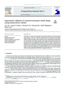
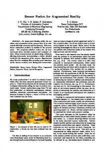
measurements need to be fused to produce a coherent input to the system controller. Experimental results from a simple split and merge maneuver are displayed in Fig. 2 which shows the separation distance over time. The radar sensor had little variance throughout the experiment except for bumps around 4.5m and 9m which have been attributed to a quantization error. The sonar sensor showed the smallest variance throughout its operating region but exhibited outliers which showed up above 4m and increased with distance between the follower vehicle and the lead vehicle. Above 8m no valid readings were found. The optical sensor had the highest variance of all sensors which increased with growing distance between follower and lead vehicle but otherwise show no adverse effects. The fused value filters out the spikes of the sonar sensor, the bumps of the radar sensor, and the noise of all sensors. output measurements, fusion
each sensor through the design of its shape. Measurements further away are discounted. The operative equation of the FUSVAF algorithm is
20 15 10
0
2 FUSVAF used for Automated Vehicles in IVHS The central concept of the IVHS is to increase highway capacity – while maintaining high speeds and safety – through reduced spacing between the vehicles. Using the scenario where vehicles move along the highway under automatic control [4], basic functions such as longitudinal and lateral control and other maneuvering techniques are carried out by the individual vehicle in coordination with other vehicles in its neighborhood. To acquire the information necessary for proper operation, a whole suite of sensors is needed. Redundant individual sensor
sonar sensor radar sensor optical sensor fused value
5
0
200
400
600
800
1000
1200
No of samples
Fig. 2: Fuzzy fusion for split/join maneuver; open loop validation and fusion of three longitudinal sensors
Experiments were also conducted for closed loop systems where the sensor input was used to control the separation distance between vehicles. The fusion performed superior compared to Probabilistic Data Association Filter and Kalman Filter in the presence of non-Gaussian noise (Fig. 3).
0.05
0
10
20
time [sec]
30
-0.05
-0.1
-0.15
Sum Squared Error 0.6693 No Noise Kalman Filter 1.9186 1.3901 PDAF Fuzzy Filter 0.8638 Fuzzy Fusion 0.8454
Fig. 3: Error spacing of follower car for closed loop sensor validation and fusion in the presence of non-Gaussian noise 3 Final Remarks This paper introduced a method for validation and fusion of redundant sensor information which came from several sensors employing different physical principles. Non-coinciding and contradicting measurements were resolved taking into account the properties of the sensors as well as the state of the system. The method is shown to filter out various kinds of Gaussian and non-Gaussian noise. The method can accept virtual measurements, i.e., values that are arrived at through functional redundancy. This feature makes the method stable against sensor failure when failure conditions revolve around spatial or physical conditions which affect several sensors – but not the one that is functionally redundant. The FUSVAF has been applied to other systems such as gas turbine power plants and aircraft engines [5]. As an extension, the
FUSVAF is not restricted to fusion on the data level. It can also be successfully employed at the feature level or decision level [6]. 4 References [1] Agogino, A., Alag, S., and Goebel, K., 1995, “A Framework for Intelligent Sensor Validation, Sensor Fusion, and Supervisory Control of Automated Vehicles in IVHS", Proceedings of the ITS America Annual Meeting, Washington, DC. [2] Goebel, K., and Agogino, A., 1996, "An Architecture for Fuzzy Sensor Validation and Fusion for Vehicle Following in Automated Highways", Proceedings of the 29th ISATA, Florence, Italy. [3] Khedkar, P., and Keshav, S., 1992, “Fuzzy Prediction of Time Series”, Proceedings of the IEEE International Conference on Fuzzy Systems, San Diego. [4] Varaiya, P., 1993, “Smart Cars on Smart Roads: Problems of Control”, IEEE Transactions on Automatic Control, vol.AC38, (no.2). [5] Bonissone, P., Chen, Y., Goebel, K., Khedkar, P., 1999, “Hybrid Soft Computing Systems: Industrial and Commercial Applications”, Proceedings of the IEEE, Sept 1999, Vol 87, No 9,pp. 1641-1667. [6] Goebel, K., Badami, V., and Perera, A., 1999, “Diagnostic Information Fusion for Manufacturing Processes”, Proceedings of the Second International Conference on Information Fusion, Fusion ’99, vol. 1, pp. 331-336.
List of Figures Fig. 1: Validation gate for the assignment of confidence values ....................................................1 Fig. 2: Fuzzy fusion for split/join maneuver; open loop validation and fusion of three longitudinal sensors .................................................................................................................2 Fig. 3: Error spacing of follower car for closed loop sensor validation and fusion in the presence of non-Gaussian noise..............................................................................................................3
List of Symbols ai Width of validation curve α adaptive parameter used for time series prediction σ Confidence value; variance