Sensorless Control of Permanent Magnet Synchronous Motor Using. Luenberger Observer. P. Brandstetter, P. Rech, and P. Simonik. Department of Electronics ...
PIERS Proceedings, Cambridge, USA, July 5–8, 2010
424
Sensorless Control of Permanent Magnet Synchronous Motor Using Luenberger Observer P. Brandstetter, P. Rech, and P. Simonik Department of Electronics, VSB-Technical University of Ostrava, Czech Republic
Abstract— The paper describes sensorless control of the permanent magnet synchronous motor (SMPM). The control method uses a Luenberger state reduced observer for estimation the back electromagnetic force. The speed, direction and position of rotor are calculated from this estimated quantity. The SMPM is controlled by the vector control with estimated signals in the feedback. The block scheme, mathematical description and simulation results are contained in the paper. 1. INTRODUCTION
The electric drives are a source of mechanic energy at various systems. They have a lot of advantages in comparison with the others sources mechanical energy. Especially it is high efficiency, great power density, excellent behavior at dynamic states and wide speed and torque ranges. The synchronous machine with permanent magnets (SMPM) can be considered as the most modern of them. The development of these machines is given by the evolvement of permanent magnets. Don’t forget, that the electric drives consume considerable amount electric energy, which was made. For this reason, it is very important to improve their properties. Present trends at this domain are the sensorless control. This control without speed sensor can be base on a many principles. Some of them are systems working with math model of the motor. The estimators and observers are two essential facilities for processing of them [1]. 2. LUENBERGER STATE REDUCED OBSERVER
The behavior SMPM at dynamic or steady states is based on the equations which describe electric and mechanic dependencies of AC motor quantities. The state reduced order uses similar principle. The Luenberger reduced observer reconstructs the state variables based on the knowledge of inputs and outputs of the system. The outputs of the observer are induced voltages of the motor. Mathematical model of the SMPM in the coordinates α, β and in the matrix form is given by Equation (1). This is a better option for mathematical expression of the Luenberger reduced observer [1]. · S¸ · ¸· S¸ · ¸ · ¸· S ¸ · ¸ d d uSiα uα iα u 0 RS +LS dt 0 −ωe cos θe · iα (1) = S = ω d · iS +KE · ωe · sin θ 0 uSβ u uSiβ 0 RS +LS dt e e dt iβ β Combining these equations and by modifications we the observer: S R iα − LSS 0 − L1S 0 S 0 RS 1 i d − 0 − β S = LS LS dt uiα 0 0 0 −ωe uSiβ 0 0 ωe 0
complete SMPM matrix model designed for 1 iSα L iSβ 0S S + u 0 iα uSiβ 0
0
0 0
1 LS
·
uSα uSβ
¸ (2)
where stator voltages and currents in α, β, coordinates uSα , uSβ , iSα , iSβ S S electrical induced voltages in α, β coordinates uiα , uiβ RS , LS stator resistance and inductance ωe , θe electric angular speed and rotor angle KE voltage constant of SMPM The relations among stator voltages, stator currents and back electromagnetic force are the first two voltage equations. It is possible to derive previous equations from the electric circuit with resistance, inductance and source of induced voltage. The generated voltage is proportional to the angular speed. It describes the second matrix difference equations. There is a precondition of
Progress In Electromagnetics Research Symposium Proceedings, Cambridge, USA, July 5–8, 2010
425
constant angular speed during computing cycle. Short time interval and high mechanical constant are the parameters, which help realize it. A simple reduced order observer named Luenberger observer can be applied for the stable estimation of the back electromagnetic force instead of a complex full order observer. The observer can be constructed according to following relations. We can define the state space and state vector [2]: • x = Ax + Bu where x = £ iS iS uS uS ¤T α iα β iβ y = Cx + Du
(3)
For the case where the state vector contains only two measured variables, reduced form of the Luenberger observer can be used. Therefore, we modify Equation (2) to the following form: · ¸ · S ¸ · ¸ ¸ · d xSn xn A11 A12 B1 · u = + £ ¤T A21 A22 B2 xSu dt xSu xSn = iSα iSβ where (4) ¤T £ · S ¸ xSu = uSiα uSiβ xn y =[ I 0 ]· xSu The Luenberger reduced observer can be made from the classical theory of state observers [2]. State description and meaning of the matrix will be as follows: · S ¸ · S ¸ · S ¸ • uiα iα z1 z = Dz + Fi + Gui where z= ui = i= S _ S u iSβ z2 xu = z + Li iβ (5) · ¸ · ¸ d 0 d ωe D = d [I] = F = [−LA11 + A22 + DL] = (RS + d LS ) 0 d −ωe d · G = [−LB1 + B2 ] = −
d ωe −ωe d
¸
· L = [−D +
A22 ] A−1 22
= LS
d ωe −ωe d
¸
Last mathematical adjustment is necessary due to the implementation of the observer in MatlabSimulink software. It requires state matrices only in traditional form. · S ¸ S iα xα x= • S S i x = Ax + Bu β · xSα ¸ where u= S uiα uiα y = Cx + Du y= uSiβ uSiβ (6) · ¸ · ¸ d (RS + dLS ) −ωe · (RS + dLS ) d −ωe d 0 A= B= 0 d −ωe · (RS + dLS ) d (RS + dLS ) ωe d · ¸ · ¸ d ωe 0 0 1 0 C= D = LS 0 1 −ωe d 0 0 Now we have the final equations that were used in the simulation. The parameter d is used to set the observer, respectively, gives a compromise between speed and accuracy. 3. OBSERVER APLICATION IN VECTOR CONTROL STRUCTURE
From the previous explanation we know the observer mathematic principle. After connection stator currents and voltages at stator frame reference we obtain an induced voltage waveform. But there can be the offset in this signal. Common derivation is one of the easy ways how to diminish it. The math model uses this possibility because the implementation into DSC is easy. Then it is possible to apply the function arctan 2 for calculation the rotor position. The difference with function arctan can be found only in changing the field of values from the interval [−0.5π, 0.5π] to range [−π, π]. It is necessary to add angle 0 or π to actual rotor position according to direction of angular speed. The movement direction is obtained from required speed at the first starting. Then the change of speed is evaluated from moment when the both components pass through the zero. This way
PIERS Proceedings, Cambridge, USA, July 5–8, 2010
426
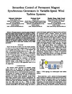
Figure 1: Control structure of PMSM with vector control and observer.
of processing appears as more accuracy in comparison to the speed direction calculated from angle increment. Angular velocity can be obtained by derivative of rotor position angle. A better option is to calculate the speed from actual values of the two components of induced voltage. However, it should be noted that this method can calculate only the size of speed. Its direction is necessary to find another way. As can be seen the direction of the signal speed is very important because it is necessary for the estimation speed and angular position. The first option to get the signal to identify it is from the derivative sign. Another option for obtaining the direction of rotation is that at direction change or stop the components of the induced voltage have to pass zero. The speed calculation is based on similar principle. The speed direction uses same signal as angle estimation. The benefit of this method is that the speed and angle calculation are independent. So the error in position estimation doesn’t affect the magnitude of speed estimation if compare it with calculation from the change of position. The speed is obtained from magnitudes of electrical induced voltages according to following equation: µ ¶ q¡ ¢ ¡ S ¢2 1 dθe est 2 S uiα + uiα sign ωe est = (7) KE dt The permanent magnet synchronous motor is controlled by typical vector control structure (see Figure 1). There is a possibility for change feedback signals by signal switch. The first switch position connects real rotor angle and speed information to feedback. The second switch position connects signals calculated by observer. 4. SIMULATION RESULTS
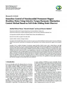
The simulation results are shown on the Figures 2 and 3. The curves of required speed and load torque were chosen so that they covered all operating states. Figure 2 shows waveforms of important quantities of SMPM with control values of incremental sensor in feedback. It is suitable for comparison the estimation precision. We can see from them, that the described method provides high-quality results. Only around zero speed there is an inaccuracy on load. Really it is not possible to obtain the true information from estimation process around zero crossing. Because the input measure voltage values are low and then back electromagnetic force is also near zero. Figure 3 contains all curves as previous figure, but there are the calculated speed and angle values in feedback. As we are allowed to see from them, all curves are almost identical. It means that this estimation structure works and provides good results.
Progress In Electromagnetics Research Symposium Proceedings, Cambridge, USA, July 5–8, 2010
Figure 2: Vector control of PMSM with incremental sensor in feedback.
Figure 3: Sensorless vector control of PMSM without incremental sensor in feedback.
427
428
PIERS Proceedings, Cambridge, USA, July 5–8, 2010
5. CONCLUSIONS
There are many problems at sensorless control of AC motor particularly at the low speed range. Because at this domain there are sluggish changes of signals and offsets, and inaccuracies of sensors are more evidently. The main advantages of sensorless vector control are following. Sensorless vector control brings the cost saving. If the drive doesn’t have the speed sensor there are smaller dimensions and weight. Next they achieve more reliability and noise immunity by elimination the number of sensors. The computing power of digital signal controller (DSC) allows application with complicated math models and their processing in real-time. The paper is one of the possibilities of PMSM sensorless control and shows the basic advantages and disadvantages of the used method. ACKNOWLEDGMENT
Research described in the paper was financially supported by the Czech Grant Agency (grant No. 102/08/0775). REFERENCES
1. Brandstetter, P. A. C., Control Drives — Modern Control Methods, VSB-Technical University of Ostrava, 1999. 2. Kim, J. K. and S. K. Sul, “High performance PMSM drives without rotational position sensors using reduced order observer,” Proceedings of Industry Applications Conference, 75–82, Orlando, USA, 1995. 3. Chlebis, P., P. Moravcik, and P. Simonik, “New method of direct torque control for threelevel voltage inverter,” Proceedings of 13th European Conference on Power Electronics and Applications, Barcelona, Spain, 2009. 4. Osmancik, L., M. Polak, P. Simonik, L. Hrdina, P. Skotnica, and P. Palacky, “Digital signal processor TMS320F2812 and its application in electric drives,” Proceedings of International Conference on Applied Electronics, 129–132, Pilsen, Czech Republic, 2006. 5. Lettl, J., “Matrix converter induction motor drive,” Proceedings of 12th International Power Electronics and Motion Control Conference, 787–792, Maribor, 2006. 6. Perdukova, D. and P. Fedor, “Fuzzy model based control of dynamic system,” Journal of Electrical Engineering, Vol. 7, No. 3, University Polytechnics Romania, 2007.