... Box, David Ehnebuske, Gopal Kakivaya, Andrew Layman, Noah Mendelsohn, ... [RSC+02] Jonathan Rosenberg, Henning Schulzrinne, Gonzalo Camarillo, ...
Service Location and Multiparty Peering for Mobile Ad-hoc Communication Dirk Kutscher and J¨org Ott Technologiezentrum Informatik (TZI), Universit¨at Bremen, Postfach 330440, 28334 Bremen, Germany, {dku|jo}@tzi.uni-bremen.de
Abstract. Flexible personal communications may require dynamically discovering, using, and combining a number of services to support the activities of a mobile user. However, many service discovery and service control protocol frameworks are not designed with requirements for ad-hoc and group communication in a changing environment in mind. In this paper, we motivate the case for personalized group communications based upon a (static) office application scenario featuring simple remote device control and then enhance the scope towards service location and dynamic establishment of group communications for mobile users: ad-hoc multiparty peering. We particularly explore the issues relating to group communication setup and robustness in the presence of changing connectivity and present a framework for mobile multiparty ad-hoc cooperation.
1
Introduction
A variety of mobile personal computing and communication equipment is available today providing a wide range of functions, e.g., to enable rich interactions with other persons or to gain access to a broad spectrum of information resources. Such personal devices are usually optimized for a certain class of tasks and, mostly due to their form factors, none of them is likely to meet all the conflicting user requirements at the same time: e.g., devices are not light and small and offer a comfortable keyboard and a large display. Given the diversity of specializations, it appears sensible to combine the strengths of the individual components dynamically as needed to carry out a certain task – rather than attempting to manufacture them into a single device that would be subject to the aforementioned tradeoffs. Component-based architectures have been used for many years e.g., for flexibly composing sophisticated communication endpoints from independent application entities or devices with well-defined interfaces. Each of these entities focuses on dedicated services; they are combined to form a coherent system by means of a component infrastructure, and different (wireless) personal (e.g., Bluetooth) and local area (e.g., WLAN) networking technologies may provide the basis for communications. A particular set of issues arises when such modular systems comprise more than two entities and operate in mobile and highly dynamic ad-hoc environments and are required to cooperate with an arbitrary number of peers to fulfill a certain task: 1) the individual entities cannot rely on well-identifiable service brokers to locate peers providing desired services; 2) different components may be located in different networks without direct
communication paths between all of them; 3) network attachments and addresses may change; 4) (group) communications between all involved entities needs to be provided; and 5) secure communications without pre-shared configurations is needed. In this paper, we address these issues for the deployment of group communication technologies in mobile ad-hoc communication environments. In section 2, we describe a sample scenario for multiparty peering, followed by a brief discussion of related work in section 3. Section 4 outlines our approaches to group communication (Mbus) and service location and association (DDA) and reviews their present limitations. Section 5 introduces extensions of the DDA approach for accommodating multiparty peering scenarios, and section 6 enhances the Mbus protocol to provide group communication services in dynamically changing network topologies. Finally, section 7 concludes this paper with a summary.
2
Modular Mobile Multimedia Conferencing
Our (non-ad-hoc, non-mobile) starting point for such a scenario is a user’s multimedia conferencing endpoint that is made up of numerous devices and software components available around the user’s desk: an IP telephone for placing and receiving regular phone calls, a workstation with camera, video communication tool, and application sharing software; a laptop with the user’s mail folder and all current documents; and a PDA, containing an address book and a calendar. When the user establishes a call, she may combine any of these entities according to her needs for a particular conversation. Application state (such as the input focus in a distributed editor, the current speaker, etc.) is shared locally so that the application entities can act coherently. This scenario can be extended to include mobile (nomadic) users who do not have an associated desk area environment – at a certain time or permanently. Examples include employees visiting co-workers in other offices or subsidiaries who want to stay connected as well as environments with non-territorial offices. Such users need to dynamically locate the devices or services they want to use in an ad-hoc fashion: in the simplest case they may just require access a single device in a foreign environment, e.g. to place a phone call controlled from a portable device, so that only point-to-point communication needs to be established dynamically, e.g. from a PDA to an IP phone[KO03]. If more application components need to be involved as for multimedia conferencing, group communication sessions need to be set up among a number of components in an ad-hoc fashion. What is needed is an ad-hoc communication environment that allows components to dynamically locate each other based upon the services they offer (service discovery and selection), securely establish bi-lateral or group communication relationships among selected entities (service association), cooperate to carry out the respective task(s) (service control), and, finally, disband the coupling again (service dissociation).
3
Related Work
Ad-hoc communication for the coordination of application components is essentially related to two research domains: 1) coordination-based protocols and architectures for
ad-hoc communication and 2) component-based application development. In addition to ad-hoc communication aspects, there is also the issue of (auto-)configuration, e.g., through mechanisms such as DHCP, IPv6 stateless auto-configuration and zeroconf protocols. Frameworks for ad-hoc communications typically provide a set of functions, i.e., service/peer location, association procedures and the actual communication mechanisms that may comprise different communication patterns such as request/response communication and event notifications. In the following, we briefly describe two prominent solutions in that area: the Service Location Protocol and Universal Plug and Play. Jini and Salutation are additional ad-hoc communication frameworks. We have provided a more detailed discussion of ad-hoc communication solutions in [KO03]. – The Service Location Protocol (SLP, [GPVD99]) is a framework for service discovery and selection, intended for automatically configuring applications that want to use services such as network printers or remote file systems in an administrative domain. SLP was designed to only solve the problem of locating services, not associating to the services themselves. Service association (i.e., allocating a service resource, exchanging confidential access credentials) needs to be done in a second step, with a different protocol so that SLP alone is rather incomplete for our purposes [KO03]. – Universal Plug and Play (UPnP, [Cor00]) is an architecture for device control and provides protocols for discovery, device description, transmission of control commands and event notification. UPnP is intended to provide peer-to-peer communication between different types of devices without manual configuration, e.g., in home networks where devices from different vendors are connected spontaneously. To allow these devices to interwork they must dynamically learn their capabilities and exchange information without knowing each other in advance. For most environments, component-based software development can now be considered an acknowledged design principle. We can distinguish between frameworks for the composition of program binaries such as COM and JavaBeans and distributed component architectures such as DCOM [BK98] and Corba [OMG]. The latter support spreading system components across various devices (e.g. PCs, laptops, stand-alone networked appliances, PDAs, etc.) allowing to employ dedicated pieces of equipment where appropriate or just spread the work load as needed. Many existing protocols rely on point-to-point communication between components and employ classical RPC interactions. Group communication is only used as a rendezvous mechanism for service discovery because multicast connectivity is usually restricted to single links and thus cannot be relied upon. Furthermore, many protocols are designed for static scenarios where service availability and reachability do not change after the discovery process. Such protocols are difficult to deploy in ad-hoc communication scenarios, where services can appear and disappear dynamically and where both service providers and clients may be mobile. However, we argue that group communication is an important element for service coordination because it is a natural solution for many coordination scenarios and may simplify several kinds of interactions. This is especially true for the development of
systems intended for dynamic environments where network addresses are not necessarily persistent for the duration of a session. Group communication in conjunction with, e.g., soft-state protocols help to make these systems more robust against intermittent connectivity and changing service availability. Our approach is significantly simpler than a generic multicast routing protocol for ad hoc networks, e.g., as described in [OT98] and [GLAM99], because we do not have to take large scale ad hoc networks with unconstrained mobility into account. In particular, our approach is driven by application scenarios where a user device coordinates distributed application components in a dynamic, heterogeneous network environment – which typically comprises infrastructure-based components to many of which mobile ad hoc networking (MANET) protocols are not applicable. For example in an office environment, a user’s laptop and wireless IP telephone would be connected using the fixed WLAN infrastructure and would thus rely on the available IP connectivity. In these scenarios, mobility is an issue when users and/or devices enter or leave networks, but it is not issue with respect to node mobility and changing network topologies. In our scenario, where a central user device is connected to a set of personal devices in the environment using different link layer technologies, it would not be helpful to implement a MANET protocol implementation on each device, because the device would not have to participate in MANET routing and packet forwarding anyway. Instead, it is sufficient (and more practical) to have the central user device become aware of the connected network links and the available communication peers.
4
Mbus/DDA-based Ad-hoc Peer-to-Peer Cooperation
In [KO03], we have presented a local coordination environment for mobile users that addresses service discovery and remote control of multimedia communication equipment (such as IP phones) in mobile ad-hoc networks. The Dynamic Device Association (DDA) concept is used to locate, select, get hold of, and release devices and services as described in section 4.1. The actual device interaction takes place using the Mbus we have developed for group communications component-based systems with a particular focus on multimedia conferencing (section 4.2). 4.1
Dynamic Device Association
The DDA framework addresses the discovery of and the secure association with services. It comprises five phases: 1. Service and device discovery Fixed and mobile devices announce their availability in regular intervals; in addition a query mechanism is supported. The announcements include service descriptions and rendezvous URIs to allow other entities to contact them as needed. The Session Announcement Protocol (SAP) [HPW00] is used for the announcements, augmented by a dedicated query message. Device and service descriptions are represented using the Session Description Protocol (SDP) [HJ98].
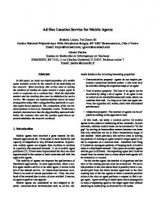
2. Device selection User devices searching for peers with certain functionality scan the announcements for the service sought. Once a set of suitable devices has been found, one or more of them are selected as required by the user or some automated algorithm. 3. Service and device association. The purpose of the association step is to initiate an application protocol session between two entities. For each device and service chosen, an association process is invoked by the user device. The selected device is contacted and, if necessary, an authentication procedure is carried out. Finally, the intended application protocol is bootstrapped. To support all kinds of application protocols (including SIP [RSC+ 02], Mbus [OPK02], HTTP [FGM+ 99], and SOAP [BEK+ 02]), the DDA session description language may contain arbitrary key-value-pairs for protocolspecific information. 4. Application protocol operation The application protocol runs in the context of the established association. This may involve all kinds of interactions between the mobile and the associated device. When no longer needed, the application protocol session is terminated (which may but need not lead to a device dissociation). In our scenario, we invoke Mbus [OPK02] as application protocol running the call and conference control profile [OKM01]. 5. Service and device dissociation Eventually, when the associated device is no longer needed, the user’s mobile device dissociates from the device and potentially makes the device fully available again to the public. In figure 1, a service client (the PDA) receives service announcements from two entities (IP phones), selects one phone and initiates the association process. After authenticating the PDA’s user, the phone answers the association request and provides the application session configuration parameters in an association process. Both parties join the corresponding application session and communicate over the specific session protocol. 4.2
Group Communication with the Mbus
We have developed a group communication environment, the Message Bus (Mbus, [OPK02]) for component-based systems in multicast-capable environments. Mbus is a message-oriented coordination protocol that provides group and point-to-point communication services, employing a network-layer addressing scheme. Each Mbus session member provides a single, unique Mbus address chosen by the application. A fully qualified Mbus address is used for Mbus unicasting, partly qualified and empty addresses for multicasting and broadcasting, respectively. The payload of an Mbus message is a list of Mbus commands with applicationdefined semantics. Commands may represent status updates, event notifications, RPCs and other interaction types. Each may include a list of parameters, such as strings, numbers and lists. Mbus also provides a set of control messages, particularly for dynamic
An n o u n
t Announcemen
cement Filtering, User selection
Association Re
on Association Resp
quest
se
Setup application session
Authenticate user, prepare application session
Application Protocol Session Termination Re Termination Re
quest
sponse
Terminate DDA session
Tear down session
Fig. 1. The DDA process
group membership tracking based upon regular announcements (mbus.hello() messages). Mbus messages may be transmitted as UDP multicast and unicast datagrams. A receiver-driven filtering process delivers those messages to applications that carry a destination address matching the own fully-qualified entity address. Messages that are directed to a single entity only (i.e., providing a sufficiently qualified destination address) can optionally be sent via unicast. The necessary Mbus-to-UDP address mapping can be inferred from the regular membership announcements as each Mbus messages carries the sender’s fully qualified Mbus address. The Mbus provides security services such as authentication and messages integrity based on hashed message authentication codes (HMACs) and confidentiality based on encryption (relying on symmetric cryptography and shared keys). In order to join an Mbus session, an application has to know the Mbus transport address (i.e., multicast address and port number) and security parameters, which are distributed out-of-band, i.e., configured manually or communicated using other protocols. In this particular case, we use the DDA protocol. While DDA and Mbus address the need for secure establishment of ad-hoc cooperation scenarios, the present protocol mechanisms are still not capable of supporting group communications – although Mbus in principle does. This is mainly because of two reasons: Firstly, similar to other approaches, the DDA model relies on the concept of a oneto-one relationship of service providers and users. A service user contacts exactly one
DDA service provider and requests the necessary configuration data to establish a pointto-point communication session. For multiparty peering, the same user device needs to contact multiple service providers (aiming at setting up a group). But applying a series of DDA association steps will usually result in disjoint configuration settings so that the user device ends up with multiple point-to-point sessions instead of a single group session, even if each individual set of application protocol parameters is suitable for group communications. Secondly, the current Mbus transport specification [OPK02] relies on native multicast connectivity. If multicast does not work, the Mbus entities may not be able to communicate, even if an enhanced DDA mechanism is able to configure them properly for a single Mbus session. This aspect is addressed in section 6.
5
Multiparty Peering for DDA
The main requirement for a generalized DDA concept is the usability for both clientserver and multiparty association. This mainly pertains to the association phase that needs to allow for a common transport configuration to be established among all devices. Multiparty considerations may also affect renewing leases for individual devices – in which case it must be ensured that the configuration settings do not change. Using DDA to initiate an Mbus session, we need to provide an explicit address binding for each entity between the two protocols: If a user device A invites devices B and C via DDA to an Mbus session, it must be able to unambiguously recognize their respective entities in order to exclude address clashes. Finally, if a user device has multiple network interfaces to receive service announcements and to communicate with its peers, it needs to coordinate the use of multicast addresses and choose the same for Mbus communications across all interfaces. This is needed to avoid reconfiguration in case of network topology changes, e.g., if peers move from one network to another. A user device may need to allocate multicast addresses and ensure that the same address is available on all locally connected links prior to initiating the first association. The basic extension to the DDA process is to generalize the association and to enable DDA clients to not only request a configuration from a DDA service but to optionally invite a service into a session by providing it with the required session parameters. Where applicable, service entities should allow for both forms of association, i.e., be able to offer a session configuration and to be invited into a session. Service entities that are restricted to either mode indicate their preferred association mode in their service announcement to avoid unnecessary requests/response cycles. For the HTTP-based DDA protocol we have implemented the “invitation” mode with an HTTP POST [FGM+ 99] request. Note that the authentication requirements do not change for association invitations: for digest authentication, the DDA client would still provide the credentials in the request message. For DDA for Mbus sessions, we have defined additional attributes for the session description that allow both parties to express their Mbus and corresponding UDP/IP endpoint addresses. Because both parties have to know each other’s addresses in advance, we allow for both the request and the response in every DDA HTTP request (GET and POST) to contain a message body. For
example, when a DDA service is invited and has received a corresponding association invitation, it will send a session description fragment responding to the request and thus provide the required address information.
A
B
C
Announcemen t
t Announcemen Filtering, User selection
Association Re
quest Association Re
quest
Mbus configurat ion A’s Mbus and UD P/IP address
uration Mbus config dress d UDP/IP ad A’s Mbus an
on Association Resp
se
d UDP/IP ad C’s Mbus an B’s Mbus and UDP/IP addres s
dress
Setup application session
Application Protocol Session
Application Protocol Session
Fig. 2. DDA in invitation mode
Figure 2 depicts the message exchange for the DDA invitation mode. A chooses an application session configuration and conveys this information to both B and C. After the two DDA associations have been completed, all three entities can join the Mbus session and check for the availability of the other sides, using the Mbus address information that has been exchanged in the DDA process. For scenarios where IP multicast connectivity is not available we have defined a probing process that helps to determine the optimal communication mode (e.g., multicast or direct unicast) between the initiator (the user device) and the invited service entity. The probing process is described in section 6.2.
6
Multiparty-Peering for Mbus
The initial scenario described in section 2 has implicitly assumed full multicast connectivity between all application entities – a safe assumption for an environment built around a single link of a local area network with today’s operating systems. However, this assumption is unlikely to hold as soon as mobile devices (such as PDAs or laptop computers) become involved making use of WLAN infrastructure or even engage into
ad-hoc communications with other devices using dedicated Bluetooth or infrared links, in addition to their connection to the (W)LAN. For security reasons, WLANs are usually connected via access routers or firewalls which may prevent multicast forwarding (deliberately or accidentally), WLAN access points may have multicast forwarding disabled to protect the bandwidth constrained wireless network. If different subnetworks are involved, any regular router (even if multicast-enabled) prevents Mbus messages from propagating as they are constrained to link-local communications. As Mbus-based applications rely on Mbus session-wide multicast connectivity, Mbus extensions are necessary that preserve this communication property despite the limitations listed above. We have chosen to keep Mbus simple and straightforward and have devised minimal enhancements to support non-uniformly connected Mbus entities based upon our target application scenario (rather than designing a sophisticated application-layer message routing and forwarding overlay). This section presents the Mbus enhancements designed and implemented to enable robust ad-hoc multiparty peering using Mbus. Key to the Mbus enhancements is the concept of a coordinator entity (6.1), represented by the same device that has also initiated the DDA process and brought together all the Mbus entities. The coordinator probes the connectivity to all the associated Mbus entities (6.2). All entities report the peers visible to them (6.3) and, based upon this information the coordinator determines when to forward messages between links (6.4). The proposed enhancements also deal with topology changes and failures (6.5) and require minimal changes to our existing Mbus implementation. 6.1
Coordinator Concept
As discussed in the previous section, the Mbus session is created dynamically in the context of a particular application scenario: after a service discovery phase, all the services are contacted by the initiating entity. Obviously, this very entity – the coordinator – has a complete overview of the components it has sought to carry out the intended task. Furthermore, the coordinator may have used different link layer technologies to contact the various peers so that it is the only one in a position to take up the responsibility of initially establishing reachability between all involved parties and also act as a hub if native multicast connectivity is not available. Finally, the coordinator is the only entity capable of re-invoking the DDA procedures, e.g., to update Mbus configuration parameters or to prolong service leases. Usually centralized architectures are considered risky as they introduce a potential bottleneck and a single point of failure. With the DDA scenario in mind, however, there may be no other way to establish connectivity between the entities in the first place. And, as the Mbus is used to communicate control messages only (rather than large data volumes), processing power and communication bandwidth are not considered to be problematic. While the coordinator could obviously be a single point of failure, we achieve fate-sharing with the intended application as the coordinator is also in control of the other devices; hence, its failure will likely cause the application to fail anyway. Nevertheless, we consider enhanced robustness here an important subject of further work.
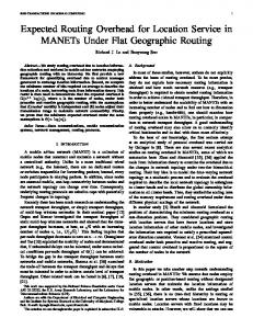
Figure 3 shows three conceivable settings with a coordinator A and three devices B, C, and D. In setting a), full multicast connectivity is available so that there is no need for the coordinator to perform any kind of message forwarding. Setting b) shows device B being on a separate link: A and B can communicate via unicast and multicast, and so can A, C, and D. But B has no way to talk to C and D and vice versa, neither with unicast nor with multicast. Setting c) depicts a scenario with B on a separate link again, with C and D sharing the same link while A is connected via a router (or some other entity blocking link-local multicast). As a result, A and B can talk via unicast and multicast and so can C and D. A and C as well as A and D can only communicate via unicast. B
C
D
A
a)
B
b)
Multicast connectivity
C
A
D
B
c)
C
D
A
Unicast link
Fig. 3. Three multiparty peering scenarios
Those three settings can be taken representatively for most connectivity variants that one may experience in local ad-hoc communications. Note also that even though we do not explicitly discuss asymmetric connectivity in this paper, we have verified that the algorithms presented below will work in those cases, too. 6.2
Connectivity Discovery
As outlined above, the coordinator needs to determine what kind of connectivity is available to its peers. As it was able to initially contact them and create an association, plain IP connectivity is obviously available. The next step is to determine whether the respective entities are also reachable via multicast or only via unicast. For this purpose, we introduce mbus.probe(m|u seq-no) messages that are parameterized with a flag indicating whether this message is sent, at the IP layer, via unicast (“u”) or multicast (“m”) and with a sequence number (for matching probes and their responses). The coordinator starts sending mbus.probe messages to each of the newly associated entities using their Mbus unicast addresses (learned from the DDA association messages). These messages are sent once via IP unicast (using the “u” flag) and once via IP multicast. (using the “m” flag). For each message sent, regardless whether unicast or multicast, the sequence number is incremented by one. The coordinator retransmits the messages up to three times to deal with possible packet loss. A receiver of such a message responds to each of the messages, again once by unicast and once by multicast – so that up to six messages are exchanged in total. Each response message – mbus.probe.ack (m|u seq-no*) – again contains a flag
indicating whether the message was sent via unicast or multicast and contains a list of mbus.probe sequence numbers received from the coordinator for the last few seconds. If the coordinator receives mbus.probe responses via unicast and multicast, acknowledging both unicast and multicast probes, full unicast and multicast connectivity is available. Otherwise, the combination of response messages received (via unicast and/or multicast) and their acknowledged sequence numbers reveal in which direction multicast connectivity is available, if at all. For simplicity, in all cases but the first, the communication between the coordinator and the probed Mbus entity will only use unicast communication. The result of this process is used to configure the message routing for both the coordinator and the Mbus entity. Connectivity probing may be repeated when topology changes are suspected, e.g., when an entity has become invisible on a link.
6.3
Visibility Reporting
Mbus entities announce their presence in regular intervals by means of mbus.hello() messages to become aware of each other. In a setting with potentially disjoint communication links, the coordinator needs to determine which Mbus entities can talk directly to each other and which require its help to forward messages. To establish this view, each Mbus entity transmits periodic visibility reports, i.e., Mbus messages containing a list of other Mbus entities it is aware of. We distinguish two kinds of visibility: native visibility refers to Mbus entities whose mbus.hello() messages were received directly, i.e., without the help of the forwarding coordinator; effective visibility refers to all Mbus entities from which mbus.hello() messages have been received recently. An Mbus visibility report is defined as mbus.visible (( [native])*), i.e., it provides a list of peers, each indicating the Mbus address being reported and a “native” flag showing whether the message has been received directly from the respective entity. If both native and relayed messages are received from another entity, the native reporting takes precedence. When all Mbus entities start communicating, only native visibility reports are possible. If the coordinator observes that all entities can see all others natively no further actions are necessary on its part. Otherwise, the coordinator can determine from the visibility reports how the Mbus session is partitioned and start forwarding messages between those partitions. All Mbus messages except for mbus.hello() are forwarded unchanged. mbus.hello() needs to receive special processing to allow distingushing native messages from relayed ones: a single parameter peer (via ) is inserted into the message yielding mbus.hello ((via )). As soon as the coordinator starts forwarding messages, Mbus entities will add also those peers to their visibility reports whose messages have been forwarded. The coordinator uses the effective visibility to determine when full connectivity of the Mbus session has been achieved. It continues to use the native visibility to constantly monitor the overall connectivity and adapt its forwarding behavior when necessary.
6.4
Message Transmission and Forwarding
Mbus message transmission is conceptually extended to support multiple interfaces per Mbus entity. A regular Mbus entity (i.e., not the coordinator) provides a multicast interface and may provide one or more unicast interfaces and uses only a single link. Each interface is basically similar to a link layer interface with routing table entries (based on Mbus addresses) pointing to this interface. The original Mbus design has a default route for all traffic pointing to the multicast interface and may have one unicast interface per known Mbus entity for the unicast optimization. For Mbus sessions with partial multicast connectivity and a coordinator acting as a “hub”, the transmission behavior of Mbus entities needs to be adapted only slightly. Mbus entities that have full multicast connectivity with their coordinator do not need to change; the above rules just work. Mbus entities that have only unicast connectivity to their coordinator and no multicast connectivity to other entities (i.e., do not see any native visibility reports except from the coordinator) use their unicast interface to the coordinator as default interface. Mbus entities that have directly reachable multicast peers but only a unicast interface to the coordinator, create two default routes and thus duplicate their outgoing Mbus messages (except for those using the unicast optimization) transmitting them via multicast and sending them to the coordinator. The coordinator is responsible for relaying Mbus messages and modifying mbus.hello messages in transit. Its forwarding functions are configured based on the visibility reporting and the connectivity discovery. It may have any number of unicast and multicast interfaces on different links. Each incoming Mbus message is examined with respect to its target Mbus address. If this is a multicast address, the coordinator forwards the message to all interfaces (except for the one it has been received on) and forwards a local copy to its own application. Otherwise, the coordinator examines – based upon native visibility reports – to which interface the message needs to be forwarded or hands the message to its local application. 6.5
Change and Failure Handling
The coordinator permanently monitors effective and native visibility as reported from each endpoint. In case multicast connectivity improves, the coordinator will notice further entities reporting native visibility of each other and so the coordinator can reduce forwarding. If multicast connectivity is lost, incomplete effective visibility reports indicates that additional forwarding needs to be installed. If the coordinator looses contact to an entity, (e.g. by missing mbus.hello() messages), it may need to re-enter the connectivity discovery again. If this does not reveal ways to re-establish connectivity (e.g. because the entity is not longer reachable), the coordinator may attempt a DDA re-association or go through the entire service location procedure again to look for a different device offering the same services.
7
Conclusions
We have described scenarios and solutions for multiparty peering of service entities, considering the aspects service discovery and group communication and the special issues for ad-hoc communication scenarios, such as changing network topologies and
peer mobility. The discussion of these scenarios has shown that group communication is a desirable feature for many component-based services in local networks. However, it has also been evident that its implementation is not always trivial, because general multicast connectivity cannot be assumed and because dynamic communication scenarios require concepts that address potential changes in network topology while maintaining a continuous group communication session at the application layer. The service discovery approach that we have presented addresses the requirements for ad-hoc communication by employing a service announcement scheme based on soft-state communication that has been designed with respect to scalability and efficiency. We have extended the DDA service association protocol to support multiparty peering and have discussed the use of these extensions for establishing Mbus sessions. Using the Mbus as a basis, we have developed a group communication model that provides the concept of a group communication session that can encompass multiple underlying multicast and unicast sessions. One key aspect of this model is a central coordinating entity that manages the individual sessions, monitors entity visibility and provide message relay functions where appropriate. By adding some minimal changes to the Mbus protocol (adding new membership information messages) and by extending the Mbus implementation requirements slightly, Mbus entities can accommodate changing multicast connectivity, dynamic changes to the group membership and mixed multicast/unicast environments – characteristics that are typical for in dynamic communication scenarios. The central role of the coordinator is not considered an issue for most cases because the fate of the coordinator is coupled to the user’s application anyway. The link-state monitoring and forwarding functions that we have described are not to be misinterpreted as elements of a general layer 3 ad-hoc networking routing protocol such as AODV [PBRD03]. While routing protocols for ad-hoc networks provide multihop routing between potentially mobile hosts in order to establish and maintain an ad-hoc IP network, our approach is much simpler and highly efficient: The main goal is to provide group communication in scenarios where no comprehensive multicast connectivity between the intended group member can be established, and the forwarding is restricted to specific messages of a selected application protocol (Mbus). Moreover, we rely on a special case, where there is always a central entity (the coordinator) that has a direct link to each of the session members. In summary, the DDA framework peered with Mbus provides a lightweight yet powerful infrastructure for ad-hoc group cooperation in dynamic mobile environments. Our approach largely builds upon existing and well-established protocols simplifying integration with all kinds of personal devices.
References [BEK+ 02] Don Box, David Ehnebuske, Gopal Kakivaya, Andrew Layman, Noah Mendelsohn, Henrik Frystyk Nielsen, Satish Thatte, and Dave Winer. Simple Object Access Protocol (SOAP) 1.1. W3C Note 08, May 2002. [BK98] N. Brown and C. Kindel. Distributed Component Object Model Protocol – DCOM/1.0, January 1998. draft-brown-dcom-v1-spec-03.txt.
[Cor00]
Microsoft Corporation. Universal Plug and Play Device Architecture. available online at http://www.upnp.org/, June 2000. [FGM+ 99] Roy T. Fielding, Jim Gettys, Jeffrey C. Mogul, Henry Frystyk Nielsen, Larry Masinter, Paul Leach, and Tim Berners-Lee. Hypertext Transfer Protocol – HTTP/1.1. RFC 2616, June 1999. [GLAM99] J. J. Garcia-Luna-Aceves and Ewerton L. Madruga. A multicast routing protocol for ad-hoc networks. In INFOCOM, pages 784–792, 1999. [GPVD99] Erik Guttmann, Charles Perkins, John Veizades, and Michael Day. Service Location Protocol, Version 2. RFC 2608, June 1999. [HJ98] Mark Handley and Van Jacobsen. Session Description Protocol. RFC 2327, April 1998. [HPW00] Mark Handley, Colin Perkins, and Edmung Whelan. Session Announcement Protocol. RFC 2974, October 2000. [KO03] Dirk Kutscher and J¨org Ott. Dynamic Device Access for Mobile Users. In Proceedings of the 8th Conference on Personal Wireless Communications, 2003. [OKM01] J¨org Ott, Dirk Kutscher, and Dirk Meyer. An Mbus Profile for Call Control. available online at http://www.mbus.org/, February 2001. Internet Draft draft-ietf-mmusicmbus-call-control-00.txt, Work in Progress. [OMG] OMG. CORBA/IIOP Specification. available online at http://www.omg.org/docs/formal/02-12-06.pdf. [OPK02] J¨org Ott, Colin Perkins, and Dirk Kutscher. A Message Bus for Local Coordination. RFC 3259, April 2002. [OT98] K. Obraczka and G. Tsudik. Multicast routing issues in ad hoc networks, 1998. [PBRD03] Charles E. Perkins, Elizabeth M. Belding-Royer, and Samir R. Das. Ad hoc OnDemand Distance Vector (AODV) Routing, February 2003. Internet Draft draft-ietfmanet-aodv-13.txt, Work in Progress. [RSC+ 02] Jonathan Rosenberg, Henning Schulzrinne, Gonzalo Camarillo, Alan Johnston, Jon Peterson, Robert Sparks, Mark Handley, and Eve Schooler. SIP: Session Initiation Protocol. RFC 3261, June 2002.