Design of a Generic, Interactive, Virtual and Remote Electrical Engineering. Laboratory. H. H. Saliah. Centre de Recherche LICEF, Télé-Université du Québec.
Session 12c6 Design of a Generic, Interactive, Virtual and Remote Electrical Engineering Laboratory H. H. Saliah Centre de Recherche LICEF, Télé-Université du Québec Montreal, Quebec, CANADA E. Nurse École de Technologie Supérieure, Montreal, Quebec Abstract- This paper presents a work-in progress concept of a generic interactive virtual and remote engineering laboratory. The laboratory, accessible over heterogeneous computer networks (LAN/WAN), is a collaborative learning environment where teachers and students can interact and perform laboratory experiments. To demonstrate its usefulness, feasibility, performance and challenges, we will incorporate a stepper motor data acquisition system so that students will be able to command it via the Internet instead of attending a regular laboratory session. This stepper motor system set-up will give students the ability to experiment from any personal computer and to do so as much as they wish. As well, a concrete learning scenario design permits us to carefully develop software and hardware components that will complement the overall laboratory concept, and make it more student-friendly and accessible. Index terms- Laboratory innovations, Teamwork, Learning Environment, Computer aided data acquisition.
Introduction A Virtual and Remote Electrical Engineering Laboratory is an Internet-based Virtual Learning and Training Environment (VLTE) where learners and teachers can interact with one another as well as with computer-based simulators or with lab equipment, regardless of temporal or geographical constraints. The electrical engineering virtual laboratory permits users the following functionalities: 1. 2. 3.
4.
running experiments by interacting with instruments and remote mechanisms; achieving experimental simulations using numerical models; accomplishing only those tasks that are used for measurement or for local/distant commands sent across simple interfaces, i.e. interactive software; benefiting from a computer network using the functionalities of a central resource, as well as from pedagogical and technical assistance.
A. Abecassis École Polytechnique, Montreal, Quebec This work is, in part, funded by CANARIE, an innovative, not-for-profit, industry-led and managed consortium whereby the Canadian federal government, the research community and the private sector can collaborate in encouraging the development of the Information Highway. As well, the present paper demonstrates the work carried out in the framework of a LVEST project at TéléUniversité du Québec. The objective is to develop a remote access, generic virtual laboratory concept incorporating a variety of functions that support typical science and technology laboratory activities. The remote experimentation and measurement features constitute an important element in the future of engineering laboratories. Fig.1 illustrates the concept of a virtual engineering laboratory on a network that can be easily integrated into the Virtual Campus Architecture [1] and Explora software [2] developed here at our research centre. Fig.1 demonstrates, by using an appropriate framework processing, a dedicated management system and a certain number of software interfaces and materials, that it is possible for geographically separated users to have access to real devices at different sites. It is therefore possible to share distributed material and human resources in order to achieve an otherwise unrealisable task in a local context. Due to this ability of sharing means and experiences among the actors, this attractive and interactive teaching and learning environment definitely helps reduce the costs of purchasing and maintaining expensive equipment needed both for training and research in scientific or technical teaching institutions [3, 4]. The Generic Virtual and Remote Electrical Engineering Laboratory Architecture As shown in Fig.1 for example, the graphical table shown can permit a user to communicate with remote learners by writing or drawing naturally. It is also possible, from the videoconference and remote command (A1), across the Internet network, the GPIB telecommunication bridge (protocol IEEE 488.2) from Site B, to manipulate remotely the articulated robot arm. Other operational parts such as elevators or flexible workshops can be envisaged for the
0-7803-5643-8/99/$10.00 © 1999 IEEE November 10 - 13, 1999 San Juan, Puerto Rico 29th ASEE/IEEE Frontiers in Education Conference 12c6-18
Session 12c6 future. In the same way, it is possible to have access to an electronic circuit from Site A via the videoconference
station B, in this case, the real oscilloscope connected to the electronic circuit at Site B.
Internet
Video
Router
Router é A R
M CA P
A R
(A RA (R
Video Video
Videoconference (A1) and remote control station
Graphical table
Videoconference (B) and remote measurement station
GPIB-bridge on local network
Multimedia Server
Video
Videoconference (A2) and remote measurement station
Electronic Circuit Board GPIB- bridge (IEEE488.2)- on local network
Modular measurement instruments and data acquisition inter face
Oscilloscope
Sensors and actuators
é A R A
M CA P
A R
Multimeter
(RA (R
Remote control robot arm Sample
Site A
Spectrum Analyser
Site B
Fig.1 The Virtual and Remote Electrical Engineering Laboratory Concept Based on simple experiments, we have proved the feasibility of a true, complete and interactive virtual electrical engineering lab. Other commercial collaborative tools can be used within the environment. For example, at any step in the learning process, the user can request the help of a supervisor via a video conferencing tool. We will also present the challenges connected with the computer network, operating systems and signal processing as well as current trends in the ever-expanding area of virtually simulating a rich learning and working environment. To manage the activities described in the flow diagram shown in Fig.2, four major complementary components must be integrated into the generic electrical engineering virtual laboratory Fig. 3: 1.
2.
a theoretical tutorial presentation developed using a multimedia programming language accessible either from a local machine or via a Web browser with a plugin component; a mathematical simulation developed using both Matlab [5], a computational tool well known to electrical engineering students, and Toolbook [6], a multimedia programming language named Openscript;
3.
a data acquisition and control system built using the G language [7], an emerging graphical computing paradigm that allows for modular programming, easy code reuse and the appropriate hardware. This module enables the quick setting of TCP/IP client-server architecture for remote control, remote data acquisition and remote use of lab apparatus. Session Authorization
Theoretical Teaching Data
Theoretical Teaching Data
1 Manage Theoretical Teaching Data from Drill and Practice Exercise
Drill and Practice Exercise
2 Manage Drill and Practice Information
Data from Laboratory Work
3 Manage Lab Work Information
Laboratory Work
Human Expert + System
Fig. 2 Structured Analysis and Design Technique Flow Chart of Laboratory Activities
0-7803-5643-8/99/$10.00 © 1999 IEEE November 10 - 13, 1999 San Juan, Puerto Rico 29th ASEE/IEEE Frontiers in Education Conference 12c6-19
Session 12c6 4.
a lab management interface, where students and teachers can request and determine hardware and software resources, along with the tools required to perform a given experiment.
critical input and output points in the stepper motor electronic interface using virtual oscilloscopes. Since this system is in real time mode, the learner will observe changes in position, direction, and velocity as the motor rotates after being stepped through with various frequencies corresponding to increasing or decreasing variations of steps/sec. as shown in Fig. 4.
MATLAB SIMULATIONS (LabVIEW and CLIPS)
The Hardware and User Interface
Fig. 3 The Major Complementary Components of the Generic Electrical Engineering Virtual Laboratory Learning by Doing Experiments In order to introduce an electrical or automation engineering student to motor command, the stepper motor remote data acquisition laboratory will provide the opportunity to learn about these motors without ever attending a laboratory session at their institution. Since most engineering students cannot procure expensive electronic instruments such as oscilloscopes, voltmeters etc., and since the majority of students do not have prior technical experience, this remote set-up is very economical and offers students a great tool for learning about the functionality of servomechanisms and data acquisition systems. Basically the student will learn about the parameters of the stepper motor, by changing modes and input settings to make the motor execute the operations as illustrated in Fig.3: change the rotation direction, position and speed, i.e. accelerate and decelerate the motor. Also during the experiment, the student will visualise wave propagation and
STEPPER MOTOR
DIRECTION AND SPEED ENCODER
ANALOG
DATA INTERNAL ACQUISITION CARD
POWER STAGE
ANALOG
STEPPER CONTROL
MOTION CONTROL CARD
CONTROL SIGNALS
STEP
STEPPER MOTOR CONTROL (VALUE MOTION)
calibrating a stepper motor system controlling the rotation direction of the stepper motor enabling the motor and resetting the control system understanding the relationship between a step and the number of steps required to make one complete 360 degree revolution • moving the motor shaft from one arbitrary position to another • accelerating the motor and maintaining a constant velocity as well as decelerating and bringing it to a complete stop • visualising intermediate motor control and encoder signals
DIRECTION
REMOTE EXPERIMENTATIONS (LabVIEW)
• • • •
Axis 1 Axis 2
PCI BUS
ILLUSTRATIONSMULTIMEDIA LESSONS (Toolbook)
ANALOG SIGNALS
INTERACTION WITH OTHER STUDENTS (NetMeeting)
The hardware consists of two PCI bus cards, namely the U.M.I. 4A (Motion Accessory) and the PCI-4OX-STEP (Motion Axis Control), as well as an add-on accessory, i.e. the PCI-16E-10 (Data Acquisition Card) from National Instruments [7]. Other interface cards such as the one described in reference [8] or more simple ones can be used as well. The user interface helps the students acquire the following abilities:
SHAFT
HiQ
DIGITAL OUT
MAIN PLATFORM (LabVIEW)
PCI BUS
COMPUTER
Axis 3 Axis 4 UNIVERSAL MOTION ACCESSORY
Fig. 4 Functional Stepper Motor and Data Acquisition System
0-7803-5643-8/99/$10.00 © 1999 IEEE November 10 - 13, 1999 San Juan, Puerto Rico 29th ASEE/IEEE Frontiers in Education Conference 12c6-20
Session 12c6 The Data Acquisition The PCI data acquisition system is used to acquire analogic and digital signals that are critical for the operation of the stepper controller system. When appropriate generic data acquisition program is written, so that each control signal can be visualised both from local and remote site, the student is able to distinguish between different modes of operation. The DAQ, short for data acquisition system, is also able to send output signals to other devices, receive and output digital signals and can be configured for measurement of frequency, duty cycle, digital low to high transitions, and finally digital high to low transitions
the global variable will be unbundled and sent to the hardware. Stepper Motor Multimedia Tutorial Module To help learners better perform collaborative laboratory sessions, we have developed a hybrid (CD-ROM or Webhosted) multimedia module that can be launched from the Virtual Laboratory. The module can be used to make a prelab work. The following Fig. 5 shows a typical screen. To make this learning unit more flexible, our future goal is to integrate it with our user-oriented expert system device simulator described in the next section.
The Motion Control For the purposes of commanding the stepper motor controller interface a motion control board, the ValueMotion board, made by National Instruments is used. In the experiment which the user performs, the later is able to change the direction of rotation, to enable or disable, to change modes Half /Full step, and control the way output signals are treated. The System Parameters In this experiment, an open loop stepper motor’s parameters are expressed in terms of steps, step count, and steps/sec. Also, its position is expressed as a signed number. It must be noted that the number of step counts per revolution (360 degrees) depends on the type of stepper driver used and the motor’s characteristics. The stepper board used in our experiments supports full, half, and microstep applications [9]. The Encoder Circuitry A slotted encoder is used as an indicator of the direction and velocity. The position can then be deduced from the velocity by creating a LabVIEW virtual instrument. These two signals are then converted into two digital I/O inputs or two analogic inputs. It should be noted that there are many other methods of treating encoder signals in the experimental environment. Each machine on a configured network acts as a server or as a client, depending on the learning scenario. Correspondingly, a client and user interface will be developed so as to allow the client to directly connect to the server. In this configuration, the client and server share the same data and whenever a client requests, for example, data for low level controls, the data being sent from the server to
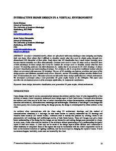
Fig. 5 A Screen Shot of the Interactive Stepper Motor Multimedia Learning Unit A Flexible User Oriented Simulated Devices In the previous section, the selected power stage shown in Fig. 6 is the well-known L297-L296 circuitry [9]. It is used in this work to demonstrate stepper motor command principles. Learners will be asked to perform the tasks presented in Appendix 1. In order to help learners better understand the functional relationships among the components, an Expert System program based on CLIPS programming language [10] is provided as a simulation tool. This section summarises the work done for this purpose. The two major parts of the system are the translator L297 and the dual full-bridge drive L298.These integrated circuits are fabricated by SGS-Thomson Microelectronics [9] . The control signals coming from either a microcomputer or a microprocessor (block A) are processed by the translator (block B) that generates the motor phase sequences received by the chopper circuits L298 (block C). The stepper motor windings (block D) are protected by a set of diodes (block E) used to overcome inductive load
0-7803-5643-8/99/$10.00 © 1999 IEEE November 10 - 13, 1999 San Juan, Puerto Rico 29th ASEE/IEEE Frontiers in Education Conference 12c6-21
Session 12c6 switching and feedback problems. Circuit overloading is controlled by a feedback (block F) to the translator and depends on the referenced voltage setting vref. The translator enables three different outputs selected by the HALF/FULL signal; changing the rotation direction, clockwise or counterclockwise, is possible via the CW/CCW input. A synchronisation signal allows the given network to work in conjunction with other circuits and this offers the possibility of controlling devices such as plotters, robots etc.
Fig. 6 Block Diagram of Dual Full-Bridge Controllers The key concept used to formalise the problem is based on Genesereth's work [11]. In fact, DART uses a deviceindependent language for describing devices and a deviceindependent inference procedure for diagnosis. The program contains only information about intended structure that is formed by the device's parts, their interconnections and expected behaviours (design description). The behaviours are expressed in terms of rules or procedures that relate the inputs, outputs and states (type and level of signals at a port at a given time). The theory allows for an implementation on non-digital or non-electronic devices with multiple levels of abstraction. The detailed conceptualisation, formalisation and implementation of this Expert System Program are beyond the scope of this paper.
3.
The system should be able to cope with the evolution of standardised communication protocols and computer languages [14]. 4. A user should be able to perform cross-platform tasks. As we have stated in a previous paper [3], virtual learning and training environments are now a reality since most of the constraints mentioned above are being removed by the expanding research on virtual laboratories. For example, Bertocco et al [15] suggests a message-based protocol instead of the Remote Procedure Call (RPC) proposed in [14] to alleviate the burden imposed by multi-user, multiinstrument requirements. High-speed telecommunication networks along with the newly developed real time Java language, permit real time measurements and control. Manufacturers are willing to adhere to the new wave of Interchangeable Virtual Instruments Foundation (IVF) which benefits from the whole VXI Consortium's experience. Cross-platform tasks can be realised through A CORBA ring regardless of the type of computer and operating systems being used. We are now considering the use of a neural networkbased filtering approach [16] to compensate for signal distortion occurring when using telecommunication networks. However, getting students to learn more about digital signal filtering is one our teaching goals. We are attempting to perform additional experiments on high-speed ATM, ADSL and ISDN networks. This project involves four educational institutions here in Montreal, as well as Bell Canada and RISQ. Conclusion This paper focuses on the use of a virtual laboratory concept to show that it is now possible to bring remote access instrumentation and control techniques within an educational framework. Thus, the virtual laboratory is not only an electrical engineering application, but can be easily extended to a broad range of activities, including the first scientific domain, i.e. medical science as well as the newly developing engineering field called mechanotronics.
The Challenges and Future Works
Appendix 1
In order to fulfil the Virtual and Remote Engineering Laboratory objectives mentioned above, the following technological considerations should be taken into account: 1. A remote controlled device should be able to react in real-time [13]. 2. The environment should be able to allow multiusers to interact with a number of real devices across the networks.
Sample of an Experimental Learning Scenario 1. 2.
Briefly present the principles of stepper motor control using help files and a tutorial. Examine the schematic in the Appendix so as to better understand the role of each of the modules in the entire circuit.
0-7803-5643-8/99/$10.00 © 1999 IEEE November 10 - 13, 1999 San Juan, Puerto Rico 29th ASEE/IEEE Frontiers in Education Conference 12c6-22
Session 12c6 3.
The clock signal is delivered by the Universal Motion Accessory at a frequency desired by the user by entering the number of step/s desired, for example 1 step/sec corresponds to 1 Hz at an amplitude of 5 Volts. 4. Set the CW/CCW input to logic 0 and 1 and each time, observe the stepper motor behaviour. 5. Set the HALF/FULL input to logic 0 and 1 and each time, observe the stepper motor behaviour. 6. Set the HALF/FULL to logic 1 and visualise with the aid of an oscilloscope the following waveforms: (A,B); (C,D); (/INH1,/INH2). 7. Set the HALF/FULL to logic 0 and visualise the following waveforms: (A,B); (C,D); (/INH1,/INH2). 8. Did you obtain the three modes of stepper motor operations? Explain the steps to be taken to obtain the operation modes. 9. How will the system be able to handle a possible overcharging of the motor? 10. Disconnect the motor from the control system and observe the corresponding signals at the points where the phase conductors of the motor were connected. 11. Propose a complementary electronic system for measurement and control of the motor shaft position and speed. 1
2
3
4
5
6
7
8
Time
Phase A Phase B Phase B Phase D
INH1 INH2
Fig. 7 Typical Signals to Observe for Half-Step Mode
References [1] G. Paquette, C. Ricciardi-Rigault, C. Paquin, S. Liégeois, E. Bleicher, "Developing the Virtual Campus Environment", Proceedings of Ed-Media 96 World Conference on Educational Telecommunication, pp. 244-249, Boston, USA, June 17-22, 1996. [2] Explora™ , LICEF Research Centre, Montreal, Canada,
[3] H. H. Saliah, M. Saad, G. A. Jamous, C. Nerguizian, D. Kodjo, "Environnements virtuels de formation et d’apprentissage sur le réseau Internet, du rêve à la réalité" Initiatives 97, Hanoi, 25 et 26 octobre 1997, http://www.refer.org/hanoi97/initiat/colloque/hassane.htm
[4] H. H. Saliah, "Formation, coopération et assistance technique à distance médiatisées", Les nouveaux défis des Écoles d’ingénieurs, pp. 111-126, Éditions AUPELF-UREF, 1996. [5] T. P. Krauss, L. Shure, J. N. Little, Signal Processing Toolbox, Mathworks, Natick, 1995. [6] Toolbook User Manual, Asymetrix, 1998. [7] Labview Basics 1 Hands-on Course, National Instruments, Austin, 1998. [8] M. Mazo, J. Urena, F. J. Rodriguez, J. J. Garcia, J. L. Lazaro, E. Santiso, F. Espinosa, R. Garcia, P. Revenga, J. C. Garcia, E. Bueno, R. Mateos, "Teaching Equipment for Training in the Control of DC, Brusless and Stepper Servomotors", IEEE Trans. on Education. Vol. 41, No. 2, pp. 146-157, May 1998. [9] Designer's Guide to Power Products. Application Manual, SGS-Thomson Microelectronics, 1992. [10] CLIPS Basic Programming Guide, Lyndon B. Johnson Space Center, U.S., 1993. [11] M. R. Genesereth, "The Use of Design Descriptions in Automated Diagnosis", Artificial Intelligence, Vol. 24, No. 1-3, pp. 411-36, 1984. [12] F. A. Kramer, G. J. Kirk, "Monitoring process data-a practical design approach", Control Engineering, Vol. 15, No.10, pp. 105-110, 1968. [13] D. J. Ramsley, D. M. Hummels, B. E. Segee, "A Virtual Instrument Bus Using Network Programming", IEEE Instrumentation and Measurement Technology Conference, pp. 694-697, May 19-21, 1997, Ottawa, Canada. [14] H. Spoelder et al., "Virtual Instrumentation: A Survey of Standards and their Interrelation", IEEE Instrumentation and Measurement Technology Conference, pp. 676-681, May 19-21, 1997, Ottawa, Canada. [15] M. Bertocco, F. Ferraris, C. Offelli, M. Parvis, "A Client-Server Architecture for Distributed Measurement Systems", IEEE Transactions. on Instrumentation and Measurement, Vol. 47, No. 5, pp. 1143-1148, 1998. [16] S. Haykins, Neural Networks: A Comprehensive Foundation, Macmillan, Toronto, 1994
http://www.licef.teluq.uquebec.ca/gp/htmlang/prodexpl.htm
0-7803-5643-8/99/$10.00 © 1999 IEEE November 10 - 13, 1999 San Juan, Puerto Rico 29th ASEE/IEEE Frontiers in Education Conference 12c6-23