Sharing Memory in Banyan-based ATM Switches. Stream. Total Cell Loss Probability. ID. First. NC PO BP RBP DPO. Order. S1 .9 .000 .617 .000 .630 .536 .000.
Sharing Memory in Banyan-based ATM Switches Debashis Basak
Abhijit K. Choudhury
Ellen L. Hahne
Fore Systems Warrendale, PA, USA
Bell Laboratories Holmdel, NJ, USA
Bell Laboratories Holmdel, NJ, USA
Abstract
We study a multistage ATM switch in which shared-memory switching elements are arranged in a banyan topology. By \shared-memory", we mean that each switching element uses output queueing and shares its local cell bu�er memory among all its output ports. We apply a bu�er management technique called Delayed Pushout that was originally designed for multistage ATM switches with hierarchical topologies. Delayed Pushout combines a pushout mechanism, for sharing memory e�ciently among queues within the same switching element, and a backpressure mechanism, for sharing memory across switch stages. The backpressure component has a threshold to restrict the amount of sharing between stages. A synergy emerges when pushout, backpressure, and this threshold are all employed together. Using a computer simulation of the switch under bursty tra�c, we study Delayed Pushout as well as several simpler pushout and backpressure schemes under a variety of tra�c conditions. Of the ve schemes we simulate, Delayed Pushout is the only one that performs well under all load conditions.
This paper appears in IEEE Journal on Selected Areas in Communications, Vol. 15, No. 5, June 1997, pp. 881-891.
Sharing Memory in Banyan-based ATM Switches
1 Introduction Asynchronous Transfer Mode (ATM) has recently been standardized as the multiplexing and switching technique for the Broadband Integrated Services Digital Network (B-ISDN). The challenge now is to build large ATM switches that can operate at the high data transfer rates of B-ISDN and meet its performance requirements. Bu�ering is an important concern in these switches. When multiple cells arriving on di�erent input ports of a switch contend for the same output port, they need to be bu�ered within the switch. The location of the queues and the bu�er management policy can have a dramatic e�ect on the performance of the switch. Research has shown that output queueing with completely shared bu�ering achieves optimal throughput-delay performance for a single-stage switch [1]. Although an ideal shared-memory switch would have a single-stage design with the memory shared across all input and output ports, in practice it is di�cult to build a large singlestage shared-memory switch. The limitation on size comes from the increasing complexity of the memory control logic and the constraints on memory bandwidth [2]. In an N �N switch, the memory control logic needs to handle N incoming and N outgoing cells in each slot time. If the input lines of the switch have rate R bits/sec, and if the cells have the standard length C = 424 bits, then for a single-ported memory with access time � sec, the switch size N is limited by the following relation: N � C=(2 � R � � ). For example, a switch with 155 Mbps lines and a single-ported memory with access time of 21.3 ns cannot be larger than 64�64. If more lines than this must be switched, larger switches can be built by using small shared-memory switches as switching elements and arranging them in a multistage interconnection network (MIN) architecture. An important consequence is that there is less sharing of the overall bu�ering capacity. Also, since switching is performed in several stages, additional queueing delays are incurred. In this paper we study bu�er management schemes that increase the degree of bu�er sharing throughout the multistage switch. Multistage interconnection networks can be broadly classi ed into two main categories, viz., internally blocking or internally non-blocking. In an internally non-blocking switch two or more cells at di�erent input ports can be simultaneously forwarded to the desired output ports as long as all the output ports are distinct. In an internally blocking switch, it may not be possible to transfer two or more incoming cells with distinct output port destinations to
2
Basak, Choudhury and Hahne
Sharing Memory in Banyan-based ATM Switches the output ports due to contention within the switching fabric. In this study we shall focus only on a speci c class of internally blocking architectures called banyan networks . Banyan networks possess a number of desirable properties. They have a regular structure which makes them suitable for VLSI implementation. They also possess path uniqueness, i.e., there exists exactly one path connecting any input to any output in a banyan network. The establishment of such a path can be accomplished in a distributed fashion, using a simple self-routing procedure whereby the routing information at each stage is extracted directly from the destination address. The path uniqueness property ensures that when a banyan network is used as a fast packet switch, all the cells of a particular connection follow the same route. Consequently, out-of-sequence packet delivery is prevented and delay variability between cells is less, leading to simpler synchronization protocols for real-time services such as voice and video. In this paper we investigate the performance of multistage switches with output-queued, shared-memory switching elements arranged in the banyan topology. We look at simple bu�er management controls that may enhance performance, in particular, that may reduce cell loss. For example, we study a well-known technique, called Pushout , that regulates the lengths of individual queues in individual switching elements. We investigate another popular mechanism, called Backpressure , in which switching elements hold on to cells destined for downstream switching elements with full bu�ers. We also apply two other related bu�er management techniques, called Restricted Backpressure and Delayed Pushout , to sharedmemory switches with MIN topologies. (We proposed these two techniques in an earlier paper [3] for multistage shared-memory switches with hierarchical topologies [4].) This paper is organized as follows. The switch architecture and bu�er management schemes are described in detail in Sections 2 and 3, respectively. Section 4 describes the performance studies we conducted via computer simulation. Conclusions appear in Section 5. Our primary nding is that of the ve schemes we studied, the Delayed Pushout bu�er management scheme is the only one that performs very well under all the load conditions we tested.
2 Switch Architecture In this paper we use an N �N ATM switch with a MIN architecture in which each individual switching element (SE) is a b � b shared-memory module. The switch has logb N stages with
3
Basak, Choudhury and Hahne
Sharing Memory in Banyan-based ATM Switches 0
0
4
4
8
8
12
12
16
16
20
20
24
24
28
28
32
32
36
36
40
40
44
44
48
48
52
52
56
56
60
60
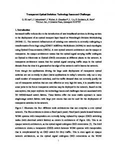
Figure 1: A 64 � 64 Omega Network. N=b SEs in each stage. Several architectures in the banyan class of networks can be used for
this switch; however, these structures have been shown to be functionally equivalent [5]. So for this study we choose the Omega network as a representative architecture of the banyan class (Fig. 1). Henceforth we shall simply refer to it as a banyan network. Cells arriving to the inputs of the switch are routed to their destinations in multiple switching stages. At each switching stage, the self-routing property of banyan networks is used to route the cell to the correct input in the next stage. Each b�b SE has its own local cell bu�er memory that can hold M cells. The SE is output-queued, and each output port of the SE has its own logical queue, but these queues share the SE's cell bu�er memory in common. Speci cally, a cell arriving at an SE is stored in a shared random access memory (RAM), and the storage location (RAM address) is recorded in a separate FIFO bu�er associated with the destination port of that particular cell. In this way a logical output queue is maintained
4
Basak, Choudhury and Hahne
Sharing Memory in Banyan-based ATM Switches for each SE output port. For each output port, periodically an address is extracted from the associated address FIFO, and the corresponding cell is sent to the output port. Our simulations assume a 64 � 64 banyan network with 4 � 4 shared-memory switching elements (Fig. 1), i.e., there are 3 stages with 16 SEs in each stage. The input lines at Stage 0 and the output lines at Stage 2 as well as all the internal lines are assumed to run at the same rate R.
3 Bu�er Management Schemes When all the tra�c is of a single loss priority, the main purpose of bu�er management schemes in a single-stage shared-memory switch is to allow the common memory within the switch to be e�ciently shared among the output ports of that switch. If all the output ports have unrestricted access to the shared memory, it is possible for one output queue to dominate the usage of the memory and starve the other queues, thereby degrading performance. When the switch is congested, it is also desirable to distribute the cell losses over the di�erent tra�c streams in some fair manner. When large multistage switches are designed using small output-queued shared-memory Switch Elements (SEs), bu�er management schemes are still used to manage the sharing of the common memory within each SE among the output ports of that SE. Moreover, multistage switches can also use bu�er management schemes to share memory across SEs. By providing controlled access to memory in other SEs, it is possible to increase the e�ective bu�er size seen by each SE and hence, improve loss performance of the switch. This paper considers ve di�erent bu�er management schemes, which we shall now describe. Consider a multistage switch, like the one in Fig. 1, without any bu�er management schemes. In this switch that is operating under No Controls (NC ), each SE only has access to its own M cells of memory which it shares among its b output ports. Each output queue in an SE has unrestricted access to the entire shared memory in the SE. Cell losses due to congestion can occur at any SE. The loss performance at each SE can be improved by an e�cient sharing of the common memory among output queues through the use of Pushout (P O) [3, 6{11]. Pushout can also be used to share memory among tra�c classes with di�erent space priorities [12,13]; in this study, however, we shall focus only on a single-priority tra�c environment. In Scheme
5
Basak, Choudhury and Hahne
Sharing Memory in Banyan-based ATM Switches P O, cells arriving to a shared memory are allowed to enter the bu�er as long as there is
space, and when the bu�er lls up, an incoming cell is allowed to enter by pushing out (i.e., overwriting) another cell that is already in the bu�er. In this paper we consider a version of Pushout in which a cell that arrives to nd the bu�er full pushes out the cell at the head of the longest queue. Although the physical space of the discarded cell is usurped, the incoming cell does not take over the discarded cell's position in its logical output port queue. Indeed, the pushing and pushed cells may belong to di�erent output port queues. Rather, the arriving cell joins its own logical queue. The Pushout approach has many performance bene ts. Pushout is fair: it allows smaller queues to increase in length at the expense of longer queues. Pushout is e�cient: no output queue is ever starved for space, and no space is ever held idle while some queue desires more; thus overall system throughput should be high. Pushout is naturally adaptive: when lots of queues are active, their rivalry keeps their queue lengths short; when only one queue is active, it is allowed to become long. Using Pushout in a multistage switch allows better sharing of the memory within an SE, but still does not allow sharing of memory among SEs. One technique for sharing among SEs is the conventional Backpressure (BP ) scheme [14{17], in which a full SE in stage l sends a backpressure signal to its upstream neighbors in stage (l?1), which causes the latter to stop sending cells downstream until the backpressure signal is removed. In this way, the memory in the upstream SEs is used to temporarily store the cells until the congestion in the downstream SE goes away. By providing access to additional bu�ering, this scheme is able to greatly improve loss performance under low to moderate load conditions. One big disadvantage of Scheme BP is that under high uniform loading and under certain non-uniform tra�c scenarios, it can lead to a phenomenon known as tree saturation [18]. Once an SE gets congested, it sends a backpressure signal to the b upstream SEs that feed it, causing them to also ll up. Then the same thing happens to the b2 SEs that are two stages upstream of the congested SE. If the overload situation persists long enough, a tree of SEs rooted at the originally congested SE can get congested, degrading the performance of the whole switch. Note that in a switch using Scheme BP , all the cell losses occur in the rst switching stage. The reason why Backpressure performs poorly under high load is that the e�ect of congestion at an SE is allowed to spread to a large number of SEs over multiple upstream stages. One solution [19] is to target only the o�ending streams by using ne-grained queueing and
6
Basak, Choudhury and Hahne
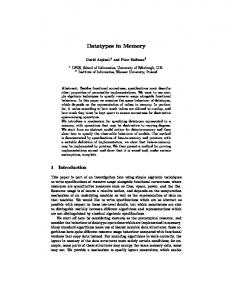
Sharing Memory in Banyan-based ATM Switches ne-grained backpressure. However, the complexity of this technique increases dramatically with switch size. A simpler scheme, called Restricted Backpressure (RBP ) [3], works by limiting the amount of memory in upstream SEs that is available to a congested SE. In contrast to Scheme BP , which allows uncontrolled access to memory in upstream SEs, Scheme RBP allows a congested SE access to only a part of the memory in SEs that are only one stage upstream. A backpressure threshold T in each SE controls the amount of local memory that can be used to temporarily store cells destined to a congested SE immediately downstream. In Fig. 2, the downstream SE D in stage l can temporarily store cells in the upstream SEs U1-U4 in stage (l ?1). As long as the total number of cells in an upstream SE is less than T , any output port of that SE that receives a backpressure signal from a downstream SE will stop sending cells to that downstream SE. Once the total number of cells in an upstream SE exceeds T , the output ports of that SE will ignore any backpressure signals they may receive and will serve their queues at full rate, until the total number of cells in the SE falls below T again. The backpressure threshold allows an SE to store cells temporarily for downstream SEs only when there is enough room for them. If the bu�er occupancy rises too high, the output ports ignore their backpressure signals and start serving their queues at full rate. This allows cells of a stream to be dropped closer to the point of congestion for that stream. Meanwhile, if some of the upstream SEs ll up completely, they in turn send backpressure signals upstream. Note that unlike Scheme BP , which dropped cells only at the switch input, i.e., the rst stage, Scheme RBP may drop cells at every stage. Pushout can be combined with the Restricted Backpressure scheme to create a new bu�er sharing strategy called Delayed Pushout (DP O) [3]. The pushout component of Scheme DP O allows memory to be shared e�ciently among queues within an SE, while the restricted backpressure component manages bu�er sharing between switch stages. In Scheme DP O, when an SE is full, it sends backpressure signals to the SEs immediately upstream so that the corresponding output ports in those SEs stop sending cells to the congested SE. The signals are withdrawn when the downstream SE ceases to be full. The backpressure signals cause the corresponding output queues in the upstream SEs to build up. When the total number of cells in an upstream SE exceeds the backpressure threshold, the output port in that SE ignores the backpressure signal and resumes serving cells from its output queue. However, instead of dropping these cells at the input of the full downstream SE, as Scheme RBP would,
7
Basak, Choudhury and Hahne
Sharing Memory in Banyan-based ATM Switches Stage l−1
Stage l
T U1 u T U2
T v D
T
w U3
T U4
Figure 2: Restricted Backpressure. DP O allows these cells to enter the downstream SE by using pushout. Meanwhile, if some
of the upstream SEs ll up completely, they in turn send backpressure signals upstream. The pushout component of Scheme DP O allows the cells destined to lightly loaded outputs to nd their way to their destinations at the expense of the cells in the longer queues. This increases the throughput and brings a degree of fairness to the allocation of space among output queues. Also, unlike the conventional backpressure scheme in which cells would have been dropped only at the rst stage of the switch, the restricted backpressure component of Scheme DP O makes it possible to shift most of the cell loss back to the input of the originally congested SE. Losses can be managed more intelligently at the input of the downstream SE than in the upstream SEs, as we shall now explain using Fig. 2. Imagine a somewhat simpli ed example where SE D is congested because of one overloaded output line v whose queue occupies the entire SE bu�er. Backpressure then causes the cells destined for SE D to back up into the upstream SEs, say U1 and U3. Suppose some cells arrive at SE U1 destined for port w in SE D. When cells must be dropped, we would like to selectively drop cells destined to the overloaded output line v. In the upstream SE U1, however, all cells for SE D are queued in a single FIFO queue at output port u, and the system does not keep track of the cells' ultimate destinations, v or w, within SE D. Therefore, if cells were dropped in the upstream SE, it would not be possible to distinguish between cells destined to the overloaded
8
Basak, Choudhury and Hahne
Sharing Memory in Banyan-based ATM Switches output line v and cells destined for the lightly loaded output line w. In contrast, when cells are dropped in SE D, the pushout mechanism there automatically discriminates against those output lines with long queues. This gives better treatment to cells destined for more lightly loaded lines, and improves the overall throughput of the switch. Although we are counting on our backpressure threshold to shift most of the loss from the input of the upstream SE to that of the downstream SE, there will still be occasional congestion of the upstream SE itself, resulting in some loss at the input to the upstream SE. Pushout within the upstream SE also prevents congested output ports in that SE from a�ecting the performance of other output ports.
4 Performance 4.1 Tra�c Model ATM switches are expected to carry many di�erent kinds of tra�c. For our performance study, however, we concentrate on bursty data tra�c; it is because of this troublesome tra�c class that ATM switches require a lot of cell bu�ering. Each input line to the switch is assumed to be connected to a single bursty data source which alternates between active and idle periods. The durations of the active and idle periods are both geometrically distributed with parameters � and respectively. Cells arrive in consecutive time slots for the duration of the active period. We assume that there is at least one cell in each active burst, but the duration of an idle period can be zero. The burst lengths are assumed to be statistically independent. Given � and , then the mean burst length Lb , the mean idle time Lidle , and the o�ered load � are given as: Lb = Lidle = � =
X1 k � � � (1 ? �) ? = 1 � X1 k � � (1 ? ) = 1 ? k 1
k =1
k
k =0
Lb
Lidle + Lb
For a given mean burst length Lb , the o�ered load � is varied by changing the mean idle duration between bursts. For the simulation results presented in this paper, Lb = 10 cells.
9
Basak, Choudhury and Hahne
Sharing Memory in Banyan-based ATM Switches Each SE has a bu�er of size M = 60 cells. For the simulations of schemes RBP and DP O, the Backpressure Threshold T = 55 cells. In this paper we look at both balanced and imbalanced tra�c patterns. Under balanced tra�c, every input line has the same o�ered load �, and each burst on an input line chooses one of the N output lines as its destination with equal probability. In the imbalanced tra�c scenarios that we study, di�erent input lines can have di�erent o�ered loads �, and the sources on di�erent input lines can favor di�erent destination output lines. More speci cally, in our imbalanced scenarios, many of the input lines are silent, and each active input line sends tra�c to only one output line.
4.2 Performance under Imbalanced Tra�c To illustrate the advantages and disadvantages of the various control schemes, we explore three examples in which the 64 � 64 banyan network of Fig. 1 experiences very imbalanced, heavy loads. Example 1 considers the eight active tra�c streams S1-S8 shown as dark lines in Fig. 3. Notice that Streams S2-S4 converge in Stage 2 on their common destination output line 3. Similarly Streams S7 and S8 converge in Stage 2 on output line 63. Streams S5 and S6 converge in Stage 1 as they head toward their common destination output line 8. The load values for our rst example are shown in Table 1. Streams S1-S4 each have o�ered load � = 0:9, and Streams S5-S8 each have � = 0:5. The table shows the cell loss probabilities for each of the ve control schemes NC , P O, BP , RBP , and DP O. The top tier of the table gives the total cell loss over all three switching stages. This loss is broken down by switching stage in the lower tiers of the table. The cell loss probability for each stage is computed relative to the cell arrival rate for that stage. For instance, RBP 's cell loss probability of 76.0% for Stream S3 at Stage 2 is computed based on the arrival rate at Stage 2, which is 23.5% lower than � = 0:9 due to losses in the preceding stage. The 95% con dence intervals for the data points in this table are all narrower than �0.002. Before consulting the actual cell loss data, let us do a crude rst-order analysis of this load pattern. Imagine that the eight streams are smooth, rather than bursty, but with the same ow rates given in Table 1. For these smooth ows, let us de ne fair loss performance as follows. For a given output port of a given switching element, the fair cell loss probability at that SE for every stream using that output port is max[(� ? 1); 0]=�, where � is the sum of
10
Basak, Choudhury and Hahne
Sharing Memory in Banyan-based ATM Switches Stage 0
Stage 1
Stage 2
S1 0
0
S2 4
4
S3 8
8
S4 12
12
16
16
20
20
S5 24
24
28
28
32
32
36
36
S6 40
40
44
44
48
48
52
52
56
56
60
60
S7 S8
Figure 3: Stream routes for Example 1. the arrival rates of those streams at that SE. The term \1" in the formula refers to the service rate of the output port. The third column of Table 1 gives this idealized fair performance for the load pattern of Example 1. Stream S1 has a load of 0.9 and shares its path with no other stream, so if it were smooth, it should experience no cell loss. Streams S5-S8 follow paths whose bottleneck links are 100% loaded, so they should also have no loss under these idealized conditions. Streams S2, S3, and S4 all go to output line 3, and the sum of their o�ered loads is 2.7, of which only 1.0 can be served. This means the cell loss probability for each of these three streams would be (2:7 ? 1:0)=2:7 = 0:630, to rst order, with a fair scheme. Now let us consult the actual cell loss data in Table 1. Notice how di�erent schemes exhibit their cell loss in di�erent switching stages. Schemes NC and P O, which do not use backpressure, have no choice but to drop cells right at the bottlenecks. For example, Streams
11
Basak, Choudhury and Hahne
Sharing Memory in Banyan-based ATM Switches Stream ID � S1 S2 S3 S4 S5 S6 S7 S8
.9 .9 .9 .9 .5 .5 .5 .5
First Order .000 .630 .630 .630 .000 .000 .000 .000
Total Cell Loss Probability NC
PO
BP
RBP DP O
.617 .626 .637 .626 .037 .037 .036 .036
.000 .630 .630 .630 .037 .037 .036 .036
.630 .630 .630 .630 .334 .334 .010 .010
.536 .536 .817 .536 .017 .016 .017 .016
Stream ID � S1 .9 S2 .9 S3 .9 S4 .9 S5 .5 S6 .5 S7 .5 S8 .5
Stage 0 Cell Loss Probability
Stream ID � S1 .9 S2 .9 S3 .9 S4 .9 S5 .5 S6 .5 S7 .5 S8 .5
Stage 1 Cell Loss Probability
Stream ID � S1 .9 S2 .9 S3 .9 S4 .9 S5 .5 S6 .5 S7 .5 S8 .5
Stage 2 Cell Loss Probability
NC
.000 .000 .000 .000 .000 .000 .000 .000 NC
.000 .000 .021 .000 .037 .037 .000 .000 NC
.617 .626 .629 .626 .000 .000 .036 .036
PO
.000 .000 .000 .000 .000 .000 .000 .000 PO
.000 .000 .000 .000 .037 .037 .000 .000 PO
.000 .630 .630 .630 .000 .000 .036 .036
BP
.630 .630 .630 .630 .334 .334 .010 .010 BP
.000 .000 .000 .000 .000 .000 .000 .000 BP
.000 .000 .000 .000 .000 .000 .000 .000
.000 .628 .632 .628 .038 .038 .017 .017
RBP DP O
.000 .000 .000 .000 .000 .000 .000 .000
.000 .000 .000 .000 .000 .000 .000 .000
RBP DP O
.000 .000 .235 .000 .017 .016 .000 .000
.000 .000 .007 .000 .038 .038 .000 .000
RBP DP O
.536 .536 .760 .536 .000 .000 .017 .016
.000 .628 .629 .628 .000 .000 .017 .017
Table 1: Cell loss probabilities for Example 1. 12 Basak, Choudhury and Hahne
Sharing Memory in Banyan-based ATM Switches and S6 see cell loss where they rst collide, in Stage 1. Streams S7 and S8 see cell loss where they rst collide, in Stage 2. In contrast, the backpressure scheme BP moves all cell loss to Stage 0. Schemes RBP and DP O do use backpressure to try to ease congestion, but if it becomes necessary to drop cells, these schemes force most of the cell loss to happen in the SE where the problem originated, as designed. First let us examine the performance of Stream S1. With Scheme NC , all the streams have roughly the same loss performance as our smooth fair model, except for Stream S1. This stream su�ers unfairly from the congestion in Stage 2 caused by Streams S2-S4. In general, when at least one output port of a switching element is overloaded causing the shared memory to be full, Scheme NC gives all streams using that SE roughly the same cell loss probability there, viz., the percentage by which the most congested output port is overloaded. In the case at hand, the unavoidable 63% loss of Streams S2-S4 is shared almost completely by Stream S1. The reason for this behavior is that whenever the SE's shared memory is nearly full, Scheme NC gives all input ports an equal chance to insert an arriving cell into the shared memory. Stream S1 su�ers unfairly under all of the schemes without pushout: NC , BP and RBP . Like NC , BP spreads the unavoidable 63% loss of Streams S2-S4 to the innocent bystander Stream S1. In general, when at least one output port of a switching element is overloaded, so that the shared memory is always nearly full, Scheme BP allows each input port to insert arriving cells into the shared memory at an equal rate � (measured in cells per cell transmission time); this rate is the fraction of time that the backpressure signal is o�. In Fig. 3, in Stage 2's top SE, there are 3 input ports feeding congested output line 3. Therefore the backpressure signal will be o� 31 of the time, and all input ports, including the one on which Stream S1 arrives, will be served at an average rate � = 13 . The excess load for each stream will back up all the way to Stage 0 and be dropped there. Thus Streams S1-S4 each see a loss probability of (0:9 ? 0:333)=0:9 = 0:630. (The di�erence between NC 's and BP 's loss mechanisms will be clearer in later examples with asymmetric loads.) We do not have a good rst-order model to predict the performance of Scheme RBP under these conditions, but it is clear from the data in Table 1 that an e�ect similar to NC 's and BP 's is at work in Scheme RBP . S5
13
Basak, Choudhury and Hahne
Sharing Memory in Banyan-based ATM Switches Fortunately, both schemes with pushout, P O and DP O, treat Stream S1 fairly, because output line 0 can use pushout to make space for an arriving cell whenever necessary. Streams S2-S4 each see the same loss of 63%, because new arrivals for output line 3 push out cells already queued at output line 3, without regard for the particular stream a cell belongs to. Next consider whether backpressure can be used to improve performance by making extra bu�ering available upstream of congestion points. Stream S1 does not need such help, and Streams S2-S4 are beyond hope, but perhaps Streams S5-S8 could bene t. Unfortunately, the plain backpressure Scheme BP makes Streams S5 and S6 much worse, raising their losses from 0.037 (with NC ) to 0.334. The problem is that BP allows Stream S3 to spread the congestion it experiences in Stage 2 back into the Stage 1 SE that S3 shares with Streams S5 and S6. Speci cally, recall that BP causes Stream S3's input port at Stage 2 to be served at rate � = 31 . This means that S3's output port at Stage 1 is only being served at rate 1 , and this creates an overload in the Stage 1 SE. Backpressure then regulates every input 3 port of that Stage 1 SE to an equal service rate of 13 . Since Streams S5 and S6 have o�ered loads of 0.5 each, their loss probabilities are each (0:5 ? 0:333)=0:5 = 0:334. As shown in Table 1, this excess is backed up into Stage 0 and dropped. The Restricted Backpressure Scheme RBP xes this problem for S5 and S6, but goes too far in the opposite direction: RBP causes such heavy losses for Stream S3 in both Stages 1 and 2 that S3's total loss substantially exceeds that of rival Streams S2 and S4. The Delayed Pushout scheme DP O gets the balance almost exactly right, causing Stream S3 to pass through Stage 1 without su�ering much loss there and without causing much loss for Streams S5 and S6. Now consider Streams S7 and S8, which collide in Stage 2. Schemes NC and P O only allow these streams to use the memory in their Stage 2 SE to manage their congestion, resulting in a cell loss probability of 0.036. Schemes RBP and DP O allow S7 and S8 to use Stage 1 memory also, which reduces their cell loss to about 0.017. Scheme BP allows S7 and S8 to bu�er their cells all the way back through Stage 0, reducing their cell loss even further to 0.010. (With this in mind, we explored several variants of DP O that allow queues to back up through multiple switch stages. However, it turned out to be di�cult to design such a scheme that behaves well in all circumstances. We explore this issue further in the next subsection on balanced loads.)
14
Basak, Choudhury and Hahne
Sharing Memory in Banyan-based ATM Switches Stage 0
Stage 1
Stage 2
S1 0
0
S2 4
4
S3 8
8
S4 12
12
16
16
20
20
S5 24
24
28
28
32
32
36
36
S6 40
40
44
44
48
48
52
52
56
56
60
60
S7 S8
Figure 4: Stream routes for Examples 2 and 3. The second and third examples use the eight active tra�c streams S1-S8 shown as dark lines in Fig. 4. The only di�erence between this routing pattern and the previous one is that Stream S2 has changed its destination from output line 3 to output line 0, which it now shares with Stream S1. We shall use the same eight streams in both Examples 2 and 3, but with di�erent stream loads in the two cases. The load values for Example 2 are shown in Table 2. As in Example 1, Streams S3 and S4 each have o�ered load � = 0:9, and Streams S5-S8 each have � = 0:5. Stream S1 now has � = 0:3, and the redirected Stream S2 now has � = 0:6. The table shows the total cell loss probability for each of the ve control schemes NC , P O, BP , RBP , and DP O. The 95% con dence intervals for the data points in this table are all narrower than �0.001. Let us again do a rst-order analysis of this load pattern. If the ows were smooth, then the only streams that should fairly experience any loss are Streams S3 and S4, because all
15
Basak, Choudhury and Hahne
Sharing Memory in Banyan-based ATM Switches Stream ID � S1 S2 S3 S4 S5 S6 S7 S8
.3 .6 .9 .9 .5 .5 .5 .5
First Order .000 .000 .444 .444 .000 .000 .000 .000
Total Cell Loss Probability NC
PO
BP
RBP DP O
.463 .441 .453 .435 .037 .037 .036 .036
.039 .023 .444 .444 .037 .037 .036 .036
.000 .167 .445 .444 .040 .041 .011 .010
.000 .162 .447 .441 .017 .017 .017 .017
.013 .009 .446 .442 .037 .037 .017 .017
Table 2: Cell loss probabilities for Example 2. the other streams follow links that are loaded to 100% or less. Streams S3 and S4 have a combined o�ered load of 1.8, so the fair cell loss probability for each of these streams is (1:8 ? 1)=1:8 = 0:444, to rst order. The third column of Table 2 shows this idealized fair performance. As in Example 1, Scheme NC gives all of Streams S1-S4 roughly the same poor performance that only S3 and S4 deserve. Scheme BP , however, treats these streams quite di�erently. To see why, note that in Fig. 4, in Stage 2's top switching element, there are now only two input ports feeding congested output line 3. Therefore the backpressure signal will be o� 21 of the time, and all input ports, including the ones on which Streams S1 and S2 arrive, will be served at an average rate � = 21 . This service rate is su�cient for S1, whose o�ered load is only 0.3, so that stream sees no loss. However, the service rate is insu�cient for Stream S2, and, of course, Streams S3 and S4. The excess load for these streams will back up all the way to Stage 0 and be dropped there. Stream S2 sees a loss probability of about (0:6 ? 0:5)=0:6 = 0:167, and Streams S3 and S4 each experience a loss probability of about (0:9 ? 0:5)=0:9 = 0:444. In this example, scheme BP does not cause Stream S3 to wreak havoc on Streams S5 and 1 at the input port in Stage 2, this means S6. Since BP regulates Stream S3's rate to � = 2 that S3's output port at Stage 1 is also being served at rate 21 . This creates an overload again 16
Basak, Choudhury and Hahne
Sharing Memory in Banyan-based ATM Switches in the Stage 1 SE. Backpressure then regulates every input port of that Stage 1 SE to an equal service rate of 21 . Fortunately this service rate is barely su�cient for Streams S5 and S6. As in Example 1, some form of pushout, either scheme P O or DP O, is essential to protect the unsaturated output line 0 from the overloaded output line 3. With P O and DP O, Streams S1 and S2 see low loss, while Streams S3 and S4 experience their unavoidable loss of about 0.444. Notice that Streams S1 and S2 bene t from the backpressure feature of DP O; their losses are even less with DP O than with P O. Stream ID � S1 S2 S3 S4 S5 S6 S7 S8
.4 .8 .9 .8 .3 .7 .2 .8
First Order .167 .167 .412 .412 .000 .000 .000 .000
Total Cell Loss Probability NC
PO
BP
RBP DP O
.440 .392 .404 .421 .051 .022 .058 .014
.193 .156 .412 .412 .039 .027 .037 .020
.000 .375 .444 .375 .000 .286 .000 .011
.004 .369 .450 .369 .000 .023 .000 .016
.194 .153 .410 .414 .035 .024 .021 .011
Table 3: Cell loss probabilities for Example 3. Our third example further explores fairness issues when streams of di�erent intensities collide. The load values for Example 3 are shown in Table 3. Note that both output lines 0 and 3 are overloaded in this case. The table shows the total cell loss probability for each of the ve control schemes NC , P O, BP , RBP , and DP O. The 95% con dence intervals for the data points in this table are all narrower than �0.001. Let us do a rst-order analysis of this load pattern. If the ows were smooth, then the only streams that should fairly experience any loss are Streams S1-S4. Streams S1 and S2 both go to output line 0, and the sum of their o�ered loads is 1.2, so the fair cell loss probability for each of these streams is (1:2 ? 1)=1:2 = 0:167, to rst order. Streams S3 and S4 both go to output line 3, and the sum of their o�ered loads is 1.7, so the fair cell loss probability for
17
Basak, Choudhury and Hahne
Sharing Memory in Banyan-based ATM Switches each of these streams is (1:7 ? 1)=1:7 = 0:412, to rst order. The third column of Table 3 shows this idealized fair performance. As in Examples 1 and 2, Scheme NC makes Streams S1 and S2 su�er as intensely as Streams S3 and S4. As in Example 2, Scheme BP treats these streams di�erently, because it o�ers the same service rate � to all four input ports of the congested SE. Recall that � is the fraction of time that the backpressure signal is o�. To rst order, � equals the largest rate such that, when each stream is throttled to the minimum of its demand rate and �, no output ports are overloaded anymore. In this example, � = 0:5, and the throttled rates of Streams S1-S4 are 0.4, 0.5, 0.5, 0.5, respectively, which leaves output line 0 with a ow of 0.9 and just barely saturates output line 3. Because the service rate is su�cient for Stream S1, that stream sees no loss. However, the service rate is insu�cient for Stream S2-S4. Streams S2 and S4 each see a loss probability of (0:8 ? 0:5)=0:8 = 0:375, and Stream S3 experiences a loss probability of (0:9 ? 0:5)=0:9 = 0:444. This excess backs up all the way to Stage 0, where it is dropped. Also, as in Example 1, Stream S3 causes the service rate � to propagate back into Stage 1, where it is interferes with Stream S6. Stream S6 sees a cell loss probability of (0:7 ? 0:5)=0:7 = 0:286. Stream S5 has such low demand that it is not a�ected. As in Example 1, using Scheme RBP instead of BP will x Stream S6's problem. Now let us consider how Scheme P O treats Streams S1-S4. (Scheme DP O is similar.) Pushout tends to equalize the queues at output lines 0 and 3. Since neither queue is ever starved for space, to rst order this should make the loss probabilities for the two queues independent. Output line 3's overall loss probability should be: (0:9 + 0:8 ? 1)=(0:9 + 0:8) = 0:412. Streams S3 and S4 should each see this same 41% loss, because cells get pushed out of output line 3's queue without regard for their particular streams. The loss data for Streams S3 and S4 in Table 3 closely match this projection. Output line 0's overall loss probability should be: (0:4 + 0:8 ? 1)=(0:4 + 0:8) = 0:167. One might expect that the individual Streams S1 and S2 would each experience this same loss probability. The simulation data in the table are reasonably close to this projection, but are not dead on: S1 sees 19.3% loss, somewhat more than its due, while S2 sees 15.6%, slightly less than its due. Such discrepancies can arise because the discrete, bursty system we simulated is more complex than a smooth uid model can capture. We will show a dramatic example of this complexity in the next paragraph.
18
Basak, Choudhury and Hahne
Sharing Memory in Banyan-based ATM Switches Another thing to notice in Example 3 is the relative performance of Streams S7 and S8, which together still barely saturate output line 63, but which now have di�erent o�ered loads. Schemes BP dramatically favors the more lightly loaded Stream S7, for reasons that should be apparent after our earlier discussion of BP 's uniform service rate �. On the other hand, Scheme NC gives better performance to the more heavily loaded Stream S8. Actually, if we convert the loss data for Streams S7 and S8 from cells-lost-per-cell-arrival to cells-lostper-cell-transmission-time, we discover that these two streams have identical loss rates of 0.0116 cells per unit time. The reason is this: the Stage 2 switching element they share has only those two streams running through it. The only time a cell can be lost is when both streams have a cell arrival at that SE, and there is only room for one new arrival in the shared memory. Suppose this happens at a rate of occurrences per unit time. Whenever it happens, each stream gets an equal chance to insert its arrival. Hence the cell loss per unit time for each stream is =2. Translating these equal rates back to cell losses per cell arrival results in a lower cell loss probability for the heavier stream. This tight correlation between the dropped cells of the two streams breaks down as more and more streams are introduced. While Scheme P O gives Streams S7 and S8 more nearly equal loss probabilities than do Schemes BP and NC , P O does favor the heavier stream S8. The reason for this is that pushouts occur only when the bu�er is full, which is correlated with recent simultaneous bursting of the two streams, which would have inserted a 50%/50% mix of cells from the two streams into the shared memory. Consider that pushout attacks cells of the two streams in proportion to their bu�er occupancies at the time. Hence the cell loss rate per unit time for the streams may not be exactly proportional to their o�ered loads �, but may be skewed in the direction of equality. Translating cell losses per unit time back to cell losses per cell arrival , this corresponds to a skew in favor of the heavier stream. This skew should shrink as more and more streams are introduced or as the o�ered loads grow (cf. S1 vs. S2 and S3 vs. S4). In summary, these three imbalanced tra�c examples suggest that pushout within each switching element is essential, so that overloaded output ports do not interfere with lightly loaded output ports. At each overloaded output port, pushout treats all streams contributing to the congestion reasonably fairly. Of the two schemes with pushout, Scheme DP O appears
19
Basak, Choudhury and Hahne
Sharing Memory in Banyan-based ATM Switches to be somewhat better than the plain P O scheme, because DP O's backpressure component makes more bu�ering available for streams that can use it.
4.3 Performance under Balanced Tra�c Now we switch to the balanced tra�c model, where each input line has the same o�ered load �, and each burst chooses its destination output line randomly and uniformly. 4.3.1
Total Loss
Fig. 5 shows the total cell loss probability as a function of o�ered load for the ve schemes NC , P O, BP , RBP , and DP O. The schemes with backpressure are shown with solid lines, while those without backpressure have dashed lines. Points are shown with 95% con dence intervals. At all load levels, each scheme with pushout does somewhat better than the corresponding scheme without pushout (i.e., compare P O with NC , and compare DP O with RBP ). As one would expect, the bene ts of pushout are less dramatic here than they were for the imbalanced load model. Under light load, the schemes with backpressure (viz., BP , RBP and DP O) do much better than those without backpressure (viz., NC and P O). For example, at � = 0:25, the cell loss probability for each of the three backpressure schemes is 1e-04, while P O's loss is 3e-04, and NC 's loss is 4e-4. Under heavy load, Scheme BP is somewhat worse than Scheme NC , because of tree saturation e�ects in which congestion spreads from an overloaded switching element back into multiple upstage switching elements. Scheme NC con nes cell loss to the troubled switching element itself, and hence is more e�cient under heavy load. Scheme RBP under heavy load is about the same as NC , because backpressure is turned o� most of the time. Under heavy load, Scheme P O is somewhat better than Scheme NC , because it drops cells even more selectively: only cells for the congested output port of the troubled switching element are dropped. Scheme DP O under heavy load performs about the same as P O, because backpressure is turned o� most of the time. DP O appears to be a reasonably good scheme at all load levels. At low loads, it shows the advantage of backpressure. At high loads, its backpressure threshold mitigates any tree
20
Basak, Choudhury and Hahne
Sharing Memory in Banyan-based ATM Switches
1e-01
1e-02 – –×
Total Cell Loss Prob.
– –× – –× 1e-03
–– ––× – –×
1e-04
– –× –– –∆
– ––× – –∆
–– –× –∆
––– ∆
–– ––× –∆
– – –– ––∆× – – –∆× – – –∆× – – –∆× –– –∆× ––∆×
Scheme NC ×
Scheme PO Scheme BP
––∆
Scheme RBP ∆
–––∆
Scheme DPO
––∆
–––∆
0.25
0.3
0.35
0.4 0.45 0.5 0.55 0.6 Offered Load ρ
0.7
0.8
0.9
Figure 5: Cell loss probabilities vs. o�ered load for the ve bu�er management schemes.
21
Basak, Choudhury and Hahne
Sharing Memory in Banyan-based ATM Switches saturation problems. Moreover, its pushout component gives a performance boost that, while dramatic under imbalanced loads, is still measurable even under balanced loads. 4.3.2
Loss per Stage
In Figs. 6-10, we break down the data from Fig. 5, looking separately at each of the three switching stages. We will discuss these per-stage losses only at low loads, because at high loads the losses of di�erent stages become correlated. For instance, a very high loss in Stage 1 means that the load actually impinging on Stage 2 is much lower than the nominal o�ered load �, which reduces the loss in Stage 2. As shown in Fig. 6, the No Controls scheme NC at low loads has roughly comparable losses for all three stages, because no matter what stage a congestion problem arises in, there is only one bu�er of size M available to deal with it. For example, at � = 0:25, the respective cell loss probabilities for Stages 0, 1 and 2 are 8.6e-05, 1.5e-04, and 1.4e-04. The total loss is 3.8e-04. The conventional Backpressure scheme BP cannot help congestion problems that originate in Stage 0. However, BP reduces the loss associated with congestion problems originating in Stages 1 and 2, by allowing the use of upstream bu�ers. Backpressure reduces these losses without completely eliminating them and shifts the location of these losses from Stages 1 and 2 back to Stage 0. As shown in Fig. 7, there are no losses at all in Stages 1 and 2 with scheme BP . At � = 0:25, BP 's loss probability in Stage 0 is 1.1e-04, only slightly higher than the unavoidable Stage 0 loss of 8.6e-05 shown on the NC plot (Fig. 6) and much less than NC 's total loss of 3.8e-04. The per-stage losses for the Restricted Backpressure scheme RBP are shown in Fig. 8. For low loads, the Stage 0 loss and the total loss are very close to those of Scheme BP . In contrast to conventional backpressure, Scheme RBP does have some losses in Stages 1 and 2, but these losses are very much lower than the Stage 0 loss. For example, with RBP , at � = 0:25, the respective cell loss probabilities for Stages 0, 1 and 2 are 1.1e-04, 1.6e-06, and 2.7e-06, and the total loss is 1.1e-04. Now let us brie y consider the two schemes that use pushout. The plots for the plain Pushout Scheme P O, given in Fig. 9, are similar in shape to those for NC . In each stage, however, the losses are a little lower with pushout than without it. For example, with P O,
22
Basak, Choudhury and Hahne
Sharing Memory in Banyan-based ATM Switches – – – ––× –× –× –× –× ––× – – – – –
1e-01
1e-02
1e-03 Cell Loss Prob. 1e-04
––× –
––× –
––× –
–× –
––× –
––× –
––× –
––× –
––×
×
Stage 0 Stage 1 Stage 2
No Controls (NC) 1e-05
1e-06 0.25
0.3
0.35
0.4 0.45 0.5 0.55 0.6 Offered Load ρ
0.7
0.8
0.9
Figure 6: Cell loss probabilities vs. o�ered load for each of the three switching stages under the No Controls (NC ) scheme. 1e-01
–
–
– – – – –
– –
1e-02
– – –
1e-03 Cell Loss Prob. 1e-04
–
×
–
Stage 0 Stage 1 Stage 2
–
Backpressure (BP) 1e-05
1e-06 0.25
0.3
0.35
0.4 0.45 0.5 0.55 0.6 Offered Load ρ
0.7
0.8
0.9
Figure 7: Cell loss probabilities vs. o�ered load for each of the three switching stages under the Backpressure (BP ) scheme.
23
Basak, Choudhury and Hahne
Sharing Memory in Banyan-based ATM Switches
1e-01 –
1e-02
– – –
1e-03 Cell Loss Prob. 1e-04
– – – – –– ––×
1e-05
1e-06
– ––×
– –×
– –×
–× –
––×
––×
– – –× ––× –
– –×
×
– –× –
– –× –
– – –× –× – –
Stage 0 Stage 1 Stage 2
Restricted Backpressure (RBP)
–– ––× 0.25
0.3
0.35
0.4 0.45 0.5 0.55 0.6 Offered Load ρ
0.7
0.8
0.9
Figure 8: Cell loss probabilities vs. o�ered load for each of the three switching stages under the Restricted Backpressure (RBP ) scheme. – – ––× –× – –× – –× – – –× –× – – –
1e-01
1e-02
1e-03 Cell Loss Prob. 1e-04
––× –
––× –
––× –
––× –
––× –
––× –
––× –
––× –
––×
×
Stage 0 Stage 1 Stage 2
Pushout (PO) 1e-05
1e-06 0.25
0.3
0.35
0.4 0.45 0.5 0.55 0.6 Offered Load ρ
0.7
0.8
0.9
Figure 9: Cell loss probabilities vs. o�ered load for each of the three switching stages under the Pushout (P O) scheme.
24
Basak, Choudhury and Hahne
Sharing Memory in Banyan-based ATM Switches – – – – –× –× – – –× –× – – –× – – ––× –
1e-01 –
1e-02
– – –
1e-03 Cell Loss Prob. 1e-04
– – – –
–– ––×
1e-05
1e-06
– ––×
– –×
– –×
–– ×
––×
––×
– –×
×
Stage 0 Stage 1 Stage 2
Delayed Pushout (DPO)
–– ––× 0.25
0.3
0.35
0.4 0.45 0.5 0.55 0.6 Offered Load ρ
0.7
0.8
0.9
Figure 10: Cell loss probabilities vs. o�ered load for each of the three switching stages under the Delayed Pushout (DP O) scheme. at � = 0:25, the respective cell loss probabilities for Stages 0, 1 and 2 are 7.3e-05, 1.2e-04, and 1.1e-04. The plots for the Delayed Pushout Scheme DP O, given in Fig. 10, are similar in shape to those for RBP . In each stage, however, the losses are a little lower with DP O than with RBP . For example, with DP O, at � = 0:25, the respective cell loss probabilities for Stages 0, 1 and 2 are 9.8e-05, 1.4e-06, and 2.3e-06. We conclude with a comparison of the three backpressure schemes. Recall that Scheme BP allows congestion incidents originating in Stage 2 to use bu�ers in both Stages 0 and 1, while RBP and DP O only allow Stage 2 problems to use Stage 1 bu�ers. Therefore, at very low loads, where tree saturation is less of a problem and bu�er sharing is most desirable, one might expect BP to have less total cell loss than RBP than DP O. (Recall that our imbalanced load scenarios showed that this extra stage of bu�ering can help certain streams under certain tra�c conditions.) However, Fig. 5 shows that this e�ect is negligible for the balanced load model and the tra�c parameters simulated here, when the performance measure is the total cell loss, summed over all stages and all source/destination pairs. Figs. 8 and 10 explain why. Schemes RBP and DP O already reduce the Stage 2 loss to such a low level, in comparison with the inherent Stage 0 loss (i.e., the loss caused by congestion incidents
25
Basak, Choudhury and Hahne
Sharing Memory in Banyan-based ATM Switches originating in Stage 0, as indicated on the NC plot in Fig. 6), that further improvements in the Stage 2 loss can have little e�ect on the overall cell loss probability. 4.3.3
Total Delay
While the primary concern of this study is loss performance, for completeness we also looked at mean cell delay data. For o�ered loads less than 0.4, all the schemes have nearly identical delay performance. For o�ered loads greater than 0.4, schemes with backpressure have higher delays than corresponding schemes without backpressure, and schemes with pushout have lower delays than corresponding schemes without pushout. Nowhere, however, does the choice of scheme cause the delay to vary by more than 27%.
5 Conclusions We studied a multistage ATM switch with a banyan topology, in which each switching element uses output queueing and shares its local cell bu�er memory among all its output ports. We applied a bu�er management technique called Delayed Pushout that was originally designed for multistage ATM switches with hierarchical topologies. Delayed Pushout uses a pushout mechanism within each switching element and a backpressure mechanism between switch stages. The backpressure component has a threshold to restrict the amount of sharing between stages. A synergy emerges when pushout, backpressure, and this threshold are all employed together. A congested switching element can gain access to the cell bu�er memory of upstream switching elements using backpressure. But the backpressure threshold helps ensure that if cells must eventually be dropped somewhere, they will be dropped back at the switching element where the congestion originated. This switching element can then employ its pushout mechanism to shed load intelligently. Using a computer simulation of the switch under bursty tra�c, we simulated Delayed Pushout as well as several simpler pushout and backpressure schemes under a variety of tra�c conditions. We found that Delayed Pushout can provide banyan networks with the substantial bene ts of backpressure under low loads, while avoiding the tree saturation problems of backpressure under high loads. The pushout component of the scheme gives a moderate improvement in overall e�ciency under balanced tra�c conditions, and it makes the network
26
Basak, Choudhury and Hahne
Sharing Memory in Banyan-based ATM Switches behave much more fairly in the presence of hot spot loads. Of the ve schemes we simulated, Delayed Pushout was the only one that performed well under all load conditions.
References [1] M. G. Hluchyj and M. J. Karol, \Queueing in Space-Division Packet Switching," in Proc. IEEE INFOCOM '88, (New Orleans, Louisiana), pp. 334{343, Mar. 1988. [2] J. Garcia-Haro and A. Jajszczyk, \ATM Shared-Memory Switching Architectures," IEEE Network Mag., vol. 8, pp. 18{26, July/August 1994. [3] A. K. Choudhury and E. L. Hahne, \Bu�er Management in a Hierarchical Shared Memory Switch," in Proc. IEEE INFOCOM '94, vol. 3, (Toronto, Canada), pp. 1410{1419, June 1994. [4] M. J. Karol and K. Y. Eng, \Performance of Hierarchical Multiplexing in ATM Switch Design," in Proc. IEEE ICC '92, (Chicago, Illinois), pp. 269{275, June 1992. [5] C.-L. Wu and T.-Y. Feng, \The Reverse Exchange Interconnection Network," IEEE Trans. Comput., vol. 29, pp. 801{811, Sept. 1980. [6] A. K. Thareja and A. K. Agarwala, \Impact of Bu�er Allocation Policies on Delays in Message Switching Networks," in Proc. IEEE INFOCOM '83, (San Diego, California), pp. 436{442, Apr. 1983. [7] A. K. Thareja and A. K. Agarwala, \On the Design of Optimal Policy for Sharing Finite Bu�ers," IEEE Trans. Commun., vol. 12, pp. 737{740, June 1984. [8] A. K. Thareja and S. K. Tripathi, \Bu�er Sharing in Dynamic Load Environment," in Proc. IEEE INFOCOM '84, (San Francisco, California), pp. 369{380, Apr. 1984. [9] S. X. Wei, E. J. Coyle, and M. T. Hsiao, \An Optimal Bu�er Management Policy for High-Performance Packet Switching," in Proc. IEEE GLOBECOM '91, (Phoenix, Arizona), pp. 924{928, Dec. 1991. [10] S. Suri, D. Tipper, and G. Meempat, \A Comparative Evaluation of Space Priority Strategies in ATM Networks," in Proc. IEEE INFOCOM '94, vol. 2, (Toronto, Canada), pp. 516{523, June 1994. [11] L. Georgiadis, I. Cidon, R. Gu�erin, and A. Khamisy, \Optimal Bu�er Sharing," IEEE J. Select. Areas Commun., vol. 13, pp. 1229{1240, Sept. 1995. [12] A. K. Choudhury and E. L. Hahne, \Space Priority Management in a Shared Memory ATM Switch," in Proc. IEEE GLOBECOM '93, vol. 3, (Houston, Texas), pp. 1375{1383, Dec. 1993. 27
Basak, Choudhury and Hahne
Sharing Memory in Banyan-based ATM Switches [13] A. K. Choudhury and E. L. Hahne, \A Simulation Study of Space Priorities in a Shared Memory ATM Switch," Journal of High Speed Networks, vol. 3, pp. 491{512, Nov. 1994. [14] S. Gianatti and A. Pattavina, \Performance Analysis of Shared-bu�ered Banyan Networks under Arbitrary Tra�c Patterns," in Proc. IEEE INFOCOM '93, vol. 3, (San Francisco, California), pp. 943{952, Mar. 1993. [15] A. I. Elwalid and I. Widjaja, \E�cient Analysis of Bu�ered Multistage Switching Networks Under Bursty Tra�c," in Proc. IEEE GLOBECOM '93, vol. 2, (Houston, Texas), pp. 1072{1078, Dec. 1993. [16] I. Iliadis and W. E. Denzel, \Analysis of Packet Switches with Input and Output Queueing," IEEE Trans. Commun., vol. 41, pp. 731{740, May 1993. [17] W. E. Denzel, A. P. J. Engbersen, and I. Iliadis, \A Flexible Shared-Bu�er Switch for ATM at Gb/s Rates," Computer Networks and ISDN Systems, vol. 27, pp. 611{624, May 1995. [18] G. F. P ster and V. A. Norton, \\Hot Spot" Contention and Combining in Multistage Interconnection Networks," IEEE Trans. Comput., vol. 34, pp. 943{948, Oct. 1985. [19] F. M. Chiussi, Y. Xia, and V. P. Kumar, \Backpressure in Shared-Memory-Based ATM Switches Under Multiplexed Bursty Sources," in Proc. INFOCOM '96, vol. 2, (San Francisco, California), pp. 830{843, Mar. 1996.
28
Basak, Choudhury and Hahne