Nano Res (2009) 2: 695 705 DOI 10.1007/s12274-009-9073-0 Research Article
00695
Shedding Light on the Crystallographic Etching of Multi-Layer Graphene at the Atomic Scale Franziska Schäffel1(
2 1 1 1 ), Jamie H. Warner , Alicja Bachmatiuk , Bernd Rellinghaus , Bernd Büchner ,
Ludwig Schultz1, and Mark H. Rümmeli1 1 2
IFW Dresden, P.O. Box 270116, D-01171 Dresden, Germany Department of Materials, University of Oxford, Parks Rd., Oxford OX1 3PH, United Kingdom
Received: 8 June 2009 / Revised: 17 July 2009 / Accepted: 17 July 2009 ©Tsinghua University Press and Springer-Verlag 2009. This article is published with open access at Springerlink.com
ABSTRACT The controlled etching of graphite and graphene by catalytic hydrogenation is potentially a key engineering route for the fabrication of graphene nanoribbons with atomic precision. The hydrogenation mechanism, though, remains poorly understood. In this study we exploit the benefits of aberration-corrected high-resolution transmission electron microscopy to gain insight to the hydrogenation reaction. The etch tracks are found to be commensurate with the graphite lattice. Catalyst particles at the head of an etch channel are shown to be faceted and the angles between facets are multiples of 30°. Thus, the angles between facets are also commensurate with the graphite lattice. In addition, the results of a post-annealing step suggest that all catalyst particles even if they are not involved in etching are actively forming methane during the hydrogenation reaction. Furthermore, the data point against carbon dissolution being a key mechanism during the hydrogenation process.
KEYWORDS Graphene, graphene nanoribbons, catalytic hydrogenation, nanoparticles
Introduction Since its isolation in 2004, graphene has been a subject of intense focus in both basic and applied research [1]. This is due to its remarkable electronic properties, such as its high electron mobility [2, 3], which potentially can give rise to a new generation of molecular electronics such as graphene-based fieldeffect transistors and interconnects with high charge carrier mobility [4]. Owing to the fact that truly twodimensional graphene is a zero-gap semiconductor, its use in nanoelectronic devices necessitates the
Address correspondence to
[email protected]
engineering of nanoribbons to introduce further confinement. The electronic properties of such ribbons can be controlled by their width and the crystallographic orientation [5 8]. Zigzag-edged nanoribbons can carry a spin current and, hence, can be used in spin-based nanoelectronic systems [9]. Armchair-edged nanoribbons show either metallic or semiconducting behavior as their width changes [6]. In addition, graphene nanoislands, such as triangular islands with well-defined zigzag edges, can show magnetic properties [10, 11].
696 To take advantage of these properties, the precise engineering of graphene ribbons with welldefined edge structure is a prerequisite to reduce the negative impact of edge effects [12 15]. Currently, state-of-the-art patterning of graphene structures is accomplished using electron beam lithography and etching techniques. However, they are limited in terms of the control afforded at the atomic level [7, 8]. Chemical routes can also lead to the fabrication of graphene with desired shapes [4, 16, 17]. Recently, it was reported that graphene nanostructures can be processed in a controlled manner via catalytic hydrogenation, where thermally activated nickel nanoparticles act as knives to cut channels along specific crystallographic directions of graphene [18, 19]. This nano-engineering approach involves the dispersion of metallic nanoparticles onto a graphene or graphite sheet and their exposure to hydrogen at elevated temperatures. In this process the catalyst helps to dissociate molecular hydrogen which then reacts with carbon (from the graphene) to form methane, leaving an etch track behind. From previous studies it is well known that methane is the only product from this reaction [20, 21]. Catalytic hydrogenation has great advantages since it provides a means for the controlled cutting of graphene sheets with atomic precision to create structures of different shapes and sizes with defined edge structures. In contrast to the scanning tunneling microscope lithography technique, accurate etching along specific crystallographic directions is intrinsic to the hydrogenation process [14]. It also allows for greater angular precision at bends. Etching of graphite by various metal and oxide particles has also been observed in atmospheres of oxygen [22 25], carbon dioxide and water [25, 26], nitrous oxide [27], and hydrogen [20, 21, 28 33] where different catalyst actions, i.e., formation of etch channels or etch pits, were observed. Although catalytic hydrogenation reactions have been investigated for a long time [20, 22, 29 33] the hydrogenation mechanism itself remains controversial [19]. However, in order to be able to effectively utilize catalytic hydrogenation as a tool to design the desired graphene nanostructures, an improved understanding of the underlying
Nano Research
Nano Res (2009) 2: 695 705 mechanisms at the nanoscale is crucial. Two main hydrogenation mechanisms have been proposed in the literature. One is the so called interfacial hydrogen mechanism, where it is argued that the catalytic gasification of carbon occurs via the dissociation of molecular H2 on the metal particle. This is then followed by the migration of atomic hydrogen on or through the catalyst to the leading graphite catalyst interface and subsequently the reaction to form CH4 takes place [22, 30]. An alternative proposal is the carbon dissolution mechanism which suggests that carbon atoms at the graphite steps first dissolve into the catalyst and then diffuse through the catalyst and react with hydrogen at the catalyst surface [30 33]. Tomita et al. found that the larger the catalyst particle, the faster the channeling rate [20]. In contrast to this, Keep et al. found a linear dependence of the surface area of the channeling particle on the amount of carbon gasified which implies that reactions at the leading catalyst–graphite interface are not rate determining, and it is reactions at the particle surface that are rate determining [30]. The interfacial hydrogen mechanism is favored by most authors [21]; however, recent work related to the controlled cutting of few layer graphene provides support for the carbon dissolution argument [19]. Hence, more detailed studies are required to better comprehend the role of the catalyst particle in the hydrogenation process at the atomic level. Aberration-corrected high-resolution transmission electron microscopy (HRTEM) provides an excellent means with which to investigate the structural properties of this process, viz. to resolve the atomic structure of the carbon atoms and catalyst particles in order to elucidate the etching process. The emergence of aberration-corrected electron microscopes allows one to examine samples that are sensitive to knock-on damage (such as graphite) with a lower accelerating voltage, where knock-on damage is significantly reduced, without the loss of resolution. In this contribution, the use of monodisperse gasphase prepared cobalt nanoparticles as the catalyst for the controlled etching of graphite/graphene via catalytic hydrogenation is presented. In addition to the hydrogenation treatment, we explored a postannealing step. The samples from these studies were
697
Nano Res (2009) 2: 695 705 investigated in detail using low voltage aberrationcorrected HRTEM. Our findings point to carbon provision occurring beyond simply the etching process at the head of a particle and provide new insight into this key engineering route for graphene device fabrication.
1. Experimental Cobalt nanoparticles were prepared by inert-gas condensation based on magnetron sputtering from a pure Co target in Ar or Ar/He atmosphere [34]. The particles were simultaneously deposited onto a graphite substrate as well as onto a carbon coated Cu grid for characterization via HRTEM prior to the hydrogenation process. For the hydrogen treatment, a graphite substrate with catalyst particles deposited on the surface was placed into a chemical vapor deposition (CVD) reactor, and the whole system was evacuated to 2 × 10 –5 mbar. The CVD reactor was equipped with a movable oven (see Fig. S-1 in the Electronic Supplementary Material (ESM)). Initially, the system was heated to the desired reaction temperature (400 900 °C) and then flooded with 60 mbar of hydrogen. At this point the oven was transferred over the graphite substrate, which then reached its preset temperature in approximately 30 s. Dynamic H2 treatment (40 mL/min) was carried out for 5 or 30 min. The vapor was then rapidly evacuated from the system, the oven removed from the reaction region and water flushed over
the reaction region of the quartz tube to provide a rapid reaction stop. In some cases an additional heat treatment in vacuum for 5 min was also carried out. During transfer of a particle sample from the particle deposition chamber into a microscope or into the CVD reactor, the particles were exposed to ambient air and may be oxidized. Further experimental details can be found elsewhere [34, 35] and in the ESM. Low voltage HRTEM was carried out using an FEI Titan3 microscope with third-order spherical aberration correction, operating at an accelerating voltage of 80 kV (i.e., below the knock-on damage threshold for graphite).
2. Results and discussion The crystallographic etching of graphite/graphene is based on the catalytic gasification of carbon in a hydrogen atmosphere forming methane via the following reaction: C(s)+2H2(g) Co CH4(g) This hydrogenation process can be induced using a variety of catalysts [18, 19, 29, 36]. In this study we use cobalt as the catalyst. Figure 1 shows some typical TEM micrographs of Co nanoparticles that have etched channels into graphite during hydrogen treatment at different temperatures. In our studies, etch tracks were first observed at a 600 °C (Figs. 1(a) and 1(b)). This temperature is significantly lower than that reported for Fe (900 °C) [18] and Ni (700 °C) [30]. As was
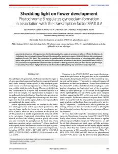
Figure 1 TEM micrographs of etch tracks formed at different temperatures after a H2 treatment of 5 min. The track lengths increase with temperature and H2 treatment time. On the whole, tracks change directions with specific angles (30°, 45°, 60°, 90°, 120°) commensurate with the graphite lattice. The tracks are terminated with a Co particle and the track width corresponds to the particle size
698
Nano Res (2009) 2: 695 705
found by others, the etch tracks were seen to always start at an exposed graphite edge (e.g., Fig. 1(a)) [20]. In general, the etch channels were terminated with a particle at the track front and the channel width corresponded to the catalyst particle size. The length of these linear cavities can be controlled by varying the reaction temperature and/or time (as confirmed by hydrogenation treatment for 30 min). Comparing the track lengths in Fig. 1(b) (etching at 600 oC) with those in Fig. 1(c) (etching at 775 oC), it can be seen that the length depends on temperature. Further,
〈
〉
〈
〉
〈
〉
they preferentially follow the 1120 and 1010 directions of the graphite lattice [20, 30]. When the etching direction changed (e.g., Figs. 1(b) and 1(c)), bending angles of 30°, 60°, 90°, and 120° were preferred, commensurate with the graphite crystal lattice, which highlights the anisotropy of graphite etching. In addition to these well-established 30° quantized etching angles, we also found some bends with angles of 45° as clearly portrayed in the triangular etch pattern in Fig. 2(a). This observation is unexpected and we are not aware of any previous reports showing a bending angle of 45° (or other odd multiples of 15°). Figure 2(b) visualizes a possible 45° angle in the graphite lattice, demonstrating that an angle of 45° can indeed be obtained within the same graphene layer. Etching along 1120 directions is energetically preferred, i.e., bending angles of 60° and 120° are most prevalent [20]. The observation of 30°-quantization involves, for example, a change from a
〈1120〉 direction to a 〈1010〉 direction.
Thus, etching along specific energetically less favorable crystallographic directions in graphite is required [19]. This also holds for the 15°-quantization as obtained here. This additional possibility for the fabrication of straight graphene nanoribbons with predefined 45° edges, which requires a mix of armchair and zigzag edges (Fig. 2(b)), might provide new physical properties further enhancing the potential of graphene. Previous studies at the atomic level using scanning tunneling microscopy (STM) investigated the etch tracks to determine the channel direction [19]. However, studies at the atomic level including the leading catalyst particle and their interface to graphite/graphene are lacking. To this end we use aberration-corrected HRTEM at 80 kV (i.e., below the knock-on damage threshold for graphite) to directly image the channels as well as the leading catalyst particle with atomic resolution to gain further insight into the mechanism of this reaction. Figure 3(a) shows a typical Co particle at the track front. Fourier enhancement of TEM micrographs allowed the structure of the graphene track to be identified and the etch direction was determined to be [1010](Figs. 3(b) and 3(c)). A schematic view of the graphite lattice including its unit cell is given in Fig. 3(d). The crystallographic directions as well as the graphene/graphite edges are also highlighted. Using this method we were able to assign the [1010] direction (along armchair edges) as the etching direction in five other cases; the [1020] direction (along zigzag edges) was only observed once. In the case of Ni nanoparticles etching graphite or few layer graphene, etching along the zigzag edges is most frequent [19, 30]. According to Tomita et al. the
〈 〉 〈 〉
ratio of the channels in the 1120 directions to channels in the 1010 directions is significantly higher for Ni than for Co [20]. However, very small Ni particles (10 nm vs particles resting on the flat basal graphite plane Co particles ≈10 nm) provides an additional means remain catalytically inactive and do not form etch for edge control. channels [20]. However, this is not strictly true. More interestingly, we have also analyzed the These latter particles are also active if the reaction structure of the catalyst particles by HRTEM. The activation barrier for carbon, which is substantially carbon hydrogenation process has been widely higher for carbon in the basal plane than for carbon studied; however, the role of the catalyst is not at steps, is overcome. An example is the formation of completely understood and detailed studies on the etch pits on the basal plane, e.g., in carbon oxidation catalyst particles are still lacking. This motivated us studies [23, 39]. Our studies also point to etchto conduct systematic TEM studies on the catalyst inactive particles being catalytically active, as is material before and after the hydrogenation process. discussed later on. Catalyst particles near the edge of The as deposited Co nanoparticles were found to be a graphene layer interact with the dangling bonds at polycrystalline oxides (see Figs. S-2(a) and S-2(b) in that edge. This interaction is stronger than with the the ESM). A simple heat treatment in vacuum led graphene sheet underneath. Once in the presence of to coalescence of the particles, but no tracks were H2 the catalytic hydrogenation reaction commences. formed (Fig. S-2(c), ESM). Strong coalescence was As the nanoparticle erodes the graphite sheet during also observed after a heat treatment in argon (Fig. this reaction it moves, maintaining maximum contact S-2(e), ESM). This suggests that the particles are with the step edge, as this is energetically more mobile on the graphite support. This is in agreement favorable [21, 40]. Thus, the driving force for the with work by Baker et al., in which different particles particle movement is the removal of carbon atoms at on graphite were explored in different atmospheres, the leading catalyst–graphite interface. Figures 4(a) including argon [37, 38]. In addition, H2 treatments (c) show three HRTEM micrographs of particles at temperatures at or below 500 °C did not lead to that have created etch channels starting at graphite track formation either (Fig. S-2(f), ESM). However, edges. With few exceptions, the particle “head” at the core–shell structures with a hexagonally close packed leading particle graphite interface was identified to (hcp) Co core and an oxide shell became apparent, be single crystalline or polycrystalline hcp Co. The suggesting that the particles were reduced and hcp Co (100) and (101) planes corresponding to lattice partly re-oxidized. Short etching channels were
〈
〉
700
Nano Res (2009) 2: 695 705
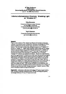
distances of 0.216 nm and 0.191 nm, respectively, are marked in each particle (Figs. 4(a) (c)). At the tail end the particles are always oxidized. Closer inspection of the TEM micrographs reveals the lattice planes of CoO (Figs. 4(a) (c)) and Co3O4 (Fig. 4(c)). For CoO the lattice distances 0.262 nm, 0.227 nm, and 0.161 nm were identified, corresponding to the (111), (200), and (220) planes, respectively. An even larger lattice distance of 0.286 nm was also found, which was assigned to the Co3O4 (220) planes. The oxide on the track end of the Co nanoparticles most certainly originates from oxidation after sample removal from the reactor; this is inevitable since those regions are not protected by the graphite. In contrast the particle heads in general seem to be protected from oxidation. This suggests that they are buried underneath the graphite. The HRTEM investigations show that the front section of the Co nanoparticle, where graphite is etched away is faceted in agreement with previous studies [22, 25, 30]. The angles between the facets are multiples of 30° (Figs. 4(a) and 4(b)). Thus, the angles between the facets are commensurate with the graphite lattice as observed for the etching bend angles. Furthernore, the nanoparticles have
an asymmetric hemispherical shape. This shape is a result of the particle maintaining maximum surface contact with the graphite edges at the etching front. This can be explained in a similar fashion to the catalytic oxidation of graphite, where the mobility of the catalyst is attributed to a stronger attractive force between the catalyst particle and the carbon atoms at the steps than with the carbon atoms in the basal plane (weaker van der Waals forces) [41]. The asymmetric particle shape at the track tip and the formation of crystallographic facets, as observed in these studies, highlight this. At moderate process temperatures (600 775 °C) channels with widths as narrow as 9 nm were observed. This is slightly larger than the mean particle diameter prior to the reaction of 7 nm. The increase in width is due to the asymmetrical reshaping of the catalyst during the hydrogenation process. This indicates a correlation between the channel and the starting catalyst size and provides a variable to control channel width. At higher process temperatures (e.g., 900 °C), the channel width distribution becomes very broad, ranging from narrow 4 nm channels to channels with widths larger than 50 nm. The reduced diameter particles
Figure 4 Co particles at the track front: the particles are hcp Co; however, the tail end is usually oxidized. Particles tend to have a half moon shape. The Co particles are facetted at the graphite particle interface with angles that are multiples of 30°
Nano Research
Nano Res (2009) 2: 695 705 arise from particle splitting similar to catalyst particle formation from thin films [42], whilst the enlarged catalyst particles are attributed to particle coalescence. This is consistent with a study by Baker et al. in which the mobility of catalyst particles residing on graphite in a gaseous environment was shown to increase with increasing temperature [37]. In addition, there appears to be a dependence on the particle size and type of track formed at higher temperatures. Small particles were seen to still form straight etch paths with sharp quantized bends, as found at lower temperatures. Medium sized particles began to exhibit a lot of turns in their tracks and the tracks themselves showed more curvature. The larger particles showed tracks with variable widths and often ceased to make tracks, but rather etched a region as if rotational movement had occurred. Furthernore, the shapes of larger particles were more varied. Figure 5(a) presents an overview micrograph illustrating these three types of etching states, some of which are highlighted in Figs. 5(b) and 5(c) to guide the eye. Curved and disklike trench formation has been observed previously in catalytically etched graphite in an oxygen atmosphere and this was attributed to the catalytic particles becoming inhomogeneously catalytically active due to poisoning by contaminating species such as sulphur dioxide [40]. In our studies it is hard to argue for selective catalyst poisoning by such pollutants at higher temperatures. It might
701
be that as particles coalesce, trace quantities of oxygen in the catalyst become sufficient to enable the formation of oxide phases in the particle that lead to local deactivation on the particle and thereby halting that region’s motion, and so flipping the particle motion, similar to the process described by Severin et al. [40]. Furthermore, it is known that at the nanoscale the melting point of nanoparticles is size-dependent [43]. Thus, another possible cause might be the inhomogeneous solidification due to the size increase. Again, these possibilities would be consistent with rotational movement, similar to the poisoning process mentioned above. Further studies are required to elucidate this point. Our data show that in order to obtain appropriate control over the etching process an optimum temperature is required, where etch formation occurs at a reasonable rate, but catalyst splitting or coalescence does not take place. In the case of Co nanoparticles, uniform tracks with a reasonable length are formed in the temperature range 700 775°C. Further studies were carried out in which the samples were exposed to hydrogen and subsequently post-annealed in vacuum. During the hydrogen treatment, etch tracks were formed in all cases as described above. However, the “inactive” particles (those particles that do not etch tracks) upon H 2 treatment showed a different appearance after post-annealing in vacuum as compared to those where only H 2 treatment without post-annealing was applied. Figure 6 provides micrographs of the different types of etch-inactive particles after H2 treatment and post-annealing for comparison. Figures 6(a) and 6(b) show particles on the flat basal graphite plane that have undergone H2 treatment only. The particles were either completely oxidized (Fig. 6(a)) or showed a core shell-type structure consisting of an inner hcp Co core and an oxide shell (Fig. 6(b)). In Figs. 6(c) (a) (b) (c) 6(f), particles that were treated Figure 5 (a) TEM micrograph of a sample H2-treated at 900 °C; (b) magnification of the in H 2 and subsequently left in selected region from (a) showing straight narrow tracks with sharp well-defined turns and thicker less well defined tracks; (c) as for (b) but with several tracks highlighted to guide the eye vacuum for 5 min at 775 °C are
702
Nano Res (2009) 2: 695 705
is the growth of a carbon nanotube from carbon precipitating from a catalyst particle [44]. Usually, the graphite roots lie at step sites at the catalyst particle surface, much as we observe in the particles in this study. It is reasonable to assume a similar process in this case, where carbon dissolves into a catalyst particle and then precipitates out forming graphitic shells. Since the graphitic shells are observed around etchinactive particles this suggests the source of carbon arises not from etching the graphite (as we might expect without hydrogen Figure 6 (a), (b) TEM micrographs of etch-inactive particles on the flat basal graphite plane after H2 treatment at 775 °C: particles oxidize completely or form core-shell particles. (c) (f) TEM being present), but by some other micrographs of similar particles after H2 treatment plus an additional 5 min in vacuum at 775 °C: means. It probably occurs through many pure hcp Co particles are encapsulated in graphitic shells that stem from the Co particle ((c), amorphous carbon species lying (d)). A few particles show a core–shell structure with an hcp Co core and an oxide shell ((e), (f)). on the surface, i.e., the graphite Around these particles one can find an etched area, highlighted orange in (e)) surface may contain amorphous shown. After this additional annealing treatment, carbon species as has often been observed in HRTEM approx. 90% of the etch-inactive Co particles were studies of carbon nanomaterials [45]. In addition, found to be encapsulated by graphitic shells (Figs. remnant CH4 (from the hydrogenation process) may 6(c) and 6(d)). Also, a few core shell particles without act as a source of carbon [46]. However, the amount carbon encapsulation (approx. 10%) can be found of CH4 that might still be present when the reaction (Figs. 6(e) and 6(f)). As highlighted in Fig. 6(e), the is halted is very low. We propose that the mobile particle is surrounded by an etched area (N. B. not etch-inactive catalyst particles absorb the amorphous an etch track). It also consists of an hcp Co core and carbon they come into contact with on the graphite an oxide shell. Figures 6(c) and 6(d) show examples surface. Upon cooling, the carbon then precipitates of the encapsulated Co particles, where the lattice out of the particle forming graphitic shells on the fringes of the (100), (002), and (101) planes of hcp Co particles. That the core shell particle resides within corresponding to lattice distances of 0.216 nm, 0.202 an etched region (e.g., Fig. 6(e)) supports this nm, and 0.191 nm, respectively, are marked. The proposal since the etched graphite surface would number of graphene shells around the circumference have been “cleaned” during the etching process and of the Co particle is seen to vary. Closer inspection of would therefore be devoid of a carbon source (viz. the particles show that the graphene shells stem from no graphitic shell formation). Etch-active catalyst the Co particle, as is marked with an arrow in Fig. particles lying at the head of an etch track stop 6(d). This opens up a rather intriguing question as to moving when the H2 supply is removed. They do how this occurs. not absorb carbon and thus do not precipitate shells Carbon encapsulated nanoparticles are usually (which they should if a gaseous carbon source, e.g., formed using synthesis routes involving the vaporremnant CH4, was available). liquid-solid (VLS) mechanism, such that the The encapsulation of the inactive particles encapsulation occurs by precipitation of carbon also provides information regarding the reaction species from the catalyst particle. A specific example mechanism. As described above, there are two
Nano Research
703
Nano Res (2009) 2: 695 705 disputed mechanisms [19, 21]. In the first and most commonly accepted, it is postulated that hydrogen is adsorbed at the catalyst surface whereupon it dissociates into atoms. These atoms can then diffuse via bulk and/or surface diffusion to the graphite particle interface at the head of a channel. The rate determining step is argued to be the chemisorption/ dissociation of hydrogen. In the second mechanism, it is argued that dissolved carbon diffuses to the outer surface and then reacts with hydrogen to form methane. This methane-forming surface reaction is proposed as the rate determining step [30]. In this study the hydrogenation reaction was brought to a rapid halt at the end of each run. In all cases, if the catalyst particles contained carbon inside them during this rapid cooling process it would be expected to either form a carbide or precipitate out. We never observed a carbide phase in any of the particles we analyzed. However, the post-annealing step in which the graphitic layers encapsulate inactive particles highlight that any carbon within the particles, upon rapid quenching, will precipitate out and suggests bulk diffusion of carbon in the particles in this instance. The fact that after undergoing the hydrogenation reaction only, etch-inactive particles do not have graphitic shells shows the efficiency with which the hydrogenation reaction removes carbon from the Co particles. The bulk hydrogen permeation rate is much higher than that for carbon (e.g., two orders of magnitude in Ni at 700 oC) [30], and hence since no shells are observed on particles after the hydrogenation reaction and no carbide phases are observed, this indicates that the gasification step (CH4 production) occurs at or near the surface of the particle. These data point against the carbon dissolution mechanism (i.e., the methaneforming surface reaction being the rate determining step). Thus, the rate determining step is probably the chemisorption/dissociation of hydrogen. This is supported by earlier findings by Keep et al. who found that the rate of carbon gasification, i.e., the etching rate, is proportional to the external surface area of the channeling particle and not to that of the leading graphite particle interface [30]. Our data are also instructive in that they show CH 4 production occurs over the entire surface of both
the active and inactive particles, because the carbon supply is not solely due to the etching of graphene layers at the head of an active particle. In this sense all particles are actively producing CH4. However, the rate of CH4 production will differ between the track-etching particles and the mobile etch-inactive particles on the graphite basal plane. For the latter, the CH4 production will be proportional to the rate of encounter with surface carbon species, whilst tracketching particles continuously produce CH4. Future in situ investigations with, for example, longer vacuum treatment times after the hydrogenation treatment should provide more insight into this process.
3. Conclusions Low-voltage HRTEM studies provide a useful means of investigating the etching of graphite/graphene by catalytic hydrogenation using Co nanoparticles. Etch-active particles revealed an asymmetric hemispherical shape at the etch front and were faceted at the graphite–particle interface. This is a result of maintaining maximum surface contact with the graphite edges at the etching front. These particles were either hcp cobalt or cobalt oxides. Furthermore, we were able to directly image the etch tracks and identify the crystallographic etch direction from HRTEM as predominantly [1010], potentially allowing for tailored graphene nanoribbon fabrication with armchair edge termination. Additional studies in which a post-annealing step was introduced, showed etch-inactive Co particles encapsulated with graphitic shells. These findings point to an additional source of carbon, probably surface carbon species, which are mopped up by mobile catalyst particles residing on the basal plane. The results point against carbon dissolution mechanisms in the catalytic hydrogenation process which is in agreement with conclusions for oxygen-based graphite etching [22 27]. Our data provide new insight into the catalytic hydrogenation of graphite at an atomic level.
Acknowledgements F.S. acknowledges funding from the Cusanuswerk. J. H. W. thanks the Glasstone Fund and Brasenose
704
Nano Res (2009) 2: 695 705
College for support. A. B. thanks the DFG RU1540/4-1.
[12] Kobayashi, Y.; Fukui, K. -I.; Enoki, T.; Kusakabe, K.; Kaburagi, Y. Observation of zigzag and armchair edges of graphite using scanning tunneling microscopy and
Electronic Supplementary Material: Supplementary material is available in the online version of this article at http://dx.doi.org/10.1007/s12274-009-9073-0 and is accessible free of charge. It contains further experimental details, information on the procedure for TEM image reconstruction, and supplementary results from particle analysis prior to channel etching.
spectroscopy. Phys. Rev. B 2005, 71, 193406. [13] Zhao, P.; Choudhury, M.; Mohanram, K.; Guo, J. Computational model of edge effects in graphene nanoribbon transistors. Nano Res. 2008, 1, 395 402. [14] Tapasztó, L.; Dobrik, G.; Lambin, P.; Biró, L. P. Tailoring the atomic structure of graphene nanoribbons by scanning tunnelling microscope lithography. Nat. Nanotechnol. 2008, 3, 397 401.
References [1] Novoselov, K. S.; Geim, A. K.; Morozov, S. V.; Jiang, D.; Zhang, Y.; Dubonos, S. V.; Grigorieva, I. V.; Firsov, A. A. Electric field effect in atomically thin carbon films. Science 2004, 306, 666 669.
[15] Cresti, A.; Nemec, N.; Biel, B.; Niebler, G.; Triozon, F.; Cuniberti, G.; Roche, S. Charge transport in disordered graphene-based low dimensional materials. Nano Res. 2008, 1, 361 394. [16] Schniepp, H. C.; Li, J. -L.; McAllister, M. J.; Saki, H.; Herrera-Alonso, M.; Adamson, D. H.; Prud’homme, R. K.;
[2] Novoselov, K. S.; Geim, A. K.; Morozov, S. V.; Jiang, D.;
Car, R.; Saville, D. A.; Aksay, I. A. Functionalized single
Katsnelson, M. I.; Grigorieva, I. V.; Dubonos, S. V.; Firsov,
graphene sheets derived from splitting graphite oxide. J.
A. A. Two-dimensional gas of massless Dirac fermions in
Phys. Chem. B 2006, 110, 8535 8539.
graphene. Nature 2005, 438, 197 200. [3] Morozov, S. V.; Novoselov, K. S.; Katsnelson, M. I.; Schedin, F.; Elias, D. C.; Jaszczak, J. A.; Geim, A. K. Giant intrinsic carrier mobilities in graphene and its bilayer. Phys. Rev. Lett. 2008, 100, 016602. [4] Li, X.; Wang, X.; Zhang, L.; Lee, S.; Dai, H. Chemically derived, ultrasmooth graphene nanoribbon semiconductors. Science 2008, 319, 1229 1232. [5] Son, Y. -W.; Cohen, M. L.; Louie, S. G. Energy gaps in graphene nanoribbons. Phys. Rev. Lett. 2006, 97, 216803. [6] Brey, L; Fertig, H. A. Electronic states of graphene nanoribbons studied with the Dirac equation. Phys. Rev. B 2006, 73, 235411.
[17] Yu, A.; Ramesh, P.; Itkis, M. E.; Bekyarova, E.; Haddon, R. C. Graphite nanoplatelet-epoxy composite thermal interface materials. J. Phys. Chem. C 2007, 111, 7565 7569. [18] Datta, S. S.; Strachan, D. R.; Khamis, S. M.; Johnson, A. T. C. Crystallographic etching of few-layer graphene. Nano Lett. 2008, 8, 1912 1915. [19] Ci, L.; Xu, Z.; Wang, L.; Gao, W.; Ding, F.; Kelly, K. F.; Yakobson, B. I.; Ajayan, P. M. Controlled nanocutting of graphene. Nano Res. 2008, 1, 116 122. [20] Tomita, A.; Tamai, Y. An optical microscopic study on the catalytic hydrogenation of graphite. J. Phys. Chem. 1974, 78, 2254 2258. [21] Konishi, S.; Sugimoto, W.; Murakami, Y.; Takasu, Y.
[7] Han, M. Y.; Özyilmaz, B.; Zhang, Y.; Kim, P. Energy band-
Catalytic creation of channels in the surface layers of
gap engineering of graphene nanoribbons. Phys. Rev.
highly oriented pyrolytic graphite by cobalt nanoparticles.
Lett. 2007, 98, 206805.
Carbon 2006, 44, 2338 2340.
[8] Chen, Z.; Lin, Y. -M.; Rooks, M. J.; Avouris, P. Graphene nano-ribbon electronics. Physica E 2007, 40, 228 232. [9] Son, Y. -W.; Cohen, M. L.; Louie, S. G. Half-metallic graphene nanoribbons. Nature 2006, 444, 347 349.
[22] Harris, P. S.; Feates, F. S.; Reuben, B. G. Controlled atmosphere electron microscopy studies of graphite gasification Ċ 4. Catalysis of the graphite-O2 reaction by silver. Carbon 1974, 12, 189 197.
[10] Fernández-Rossier, J.; Palacios, J. J. Magnetism in
[23] Yang, R. T.; Wong, C. Catalysis of carbon oxidation by
graphene nanoislands. Phys. Rev. Lett. 2007, 99,
transition metal carbides and oxides. J. Catal. 1984, 85,
177204. [11] Wang, W. L.; Meng, S.; Kaxiras, E. Graphene nanoflakes with large spin. Nano Lett. 2008, 8, 241 245.
Nano Research
154 168. [24] Goethel, P. J.; Yang, R. T. Mechanism of catalyzed graphite oxidation by monolayer channeling and
705
Nano Res (2009) 2: 695 705 monolayer edge recession. J. Catal. 1989, 119, 201 214.
2007, 19, 5006 5009.
[25] Pan, Z. J.; Yang, R. T. Catalytic behavior of transition
[36] Takasu, Y.; Konishi, S.; Miyoshi, R.; Nukii, K.; Matsuse, T.;
metal oxide in graphite gasification by oxygen, water
Sugimoto, W.; Murakami, Y. Catalytic linear grooving of
and carbon dioxide. J. Catal. 1991, 130, 161 172.
graphite surface layers by Pt, Ru, and PtRu nanoparticles.
[26] Chen, S. G.; Yang, R. T. Mechanism of alkali and alkaline earth catalyzed gasification of graphite by CO2 and H2O
Chem. Lett. 2005, 34, 1008 1009. [37] Baker, R. T. K.; Harris, P. S.; Thomas, R. B. Direct
studied by electron microscopy. J. Catal. 1992, 138, 12
observation of particle mobility on a surface in a gaseous
23.
environment. Surf. Sci. 1974, 46, 311 316.
[27] Huang, H. Y.; Yang, R. T. Catalyzed carbon–NO reaction
[38] Baker, R. T. K. In situ electron microscopy studies of
studied by scanning tunneling microscopy and ab initio
catalyst particle behavior. Catal. Rev.- Sci. Eng. 1979, 19,
molecular orbital calculations. J. Catal. 1999, 185, 286 296. [28] Tomita, A; Tamai, Y. Hydrogenation of carbons catalyzed by transition metals. J. Catal. 1972, 27, 293 300. [29]Rewick, R. T.; Wentrcek, P. R.; W ise, H. Carbon gasification in the presence of metal catalysts. Fuel 1974, 53, 274 279. [30] Keep, C. W.; Terry, S.; Wells, M. Studies of the nickel catalyzed hydrogenation of graphite. J. Catal. 1980, 66, 451 462.
161 209. [39] Chang, H.; Brad, A. J. Scanning tunneling microscopy studies of carbon-oxygen reactions on highly oriented pyrolytic graphite. J. Am. Chem. Soc. 1991, 113, 5588 5596. [40] Severin, N. ; Kirstein, S. ; Sokolov, I. M. ; Rabe, J. P. Rapid trench channeling of graphenes with catalytic silver nanoparticles. Nano Lett. 2009, 9, 457 461. [41] Hennig, G. R. Catalytic oxidation of graphite. J. Inorg. Nucl. Chem. 1962, 24, 1129 1132.
[ 3 1 ] G o e t h e l , P. J . ; Ya n g , R . T. P l a t i n u m - c a t a l y z e d
[42] Delzeit, L.; Nguyen, C. V.; Chen, B.; Stevens, R.;
hydrogenation of graphite: Mechanism studied by the
Cassell, A.; Han, J.; Meyyappan, M. Multiwalled
rates of monolayer channelling. J. Catal. 1986, 101, 341
carbon nanotubes by chemical vapor deposition using
351. [32]Goethel, P. J.; Yang, R. T. Mechanism of graphite hydrogenation catalyzed by nickel. J. Catal. 1987, 108, 356 363.
multilayered metal catalysts. J. Phys. Chem. B 2002, 106, 5629 5635. [43] Cortie, M. B.; van der Lingen, E. Catalytic gold nanoparticles. Mater. Forum 2002, 26, 1 14.
[33]Goethel, P. J.; Yang, R. T. Mechanism of graphite
[44] Rümmeli, M. H.; Schäffel, F.; Kramberger, C.; Gemming,
hydrogenation catalyzed by ruthenium particles. J. Catal.
T. Bachmatiuk, A.; Kalenczuk, R. J.; Rellinghaus, B.;
1988, 111, 220 226.
Büchner, B.; Pichler, T. Oxide-driven carbon nanotube
[34] Schäffel, F.; Kramberger, C.; Rümmeli, M. H.; Kaltofen, R.; Grimm, D.; Grüneis, A.; Mohn, E.; Gemming, T.; Pichler,
growth in supported catalyst CVD. J. Am. Chem. Soc. 2007, 129, 15772 15773.
T.; Büchner, B.; Rellinghaus, B.; Schultz, L. Carbon
[45] Warner, J. H.; Schäffel, F.; Zhong, G.; Rümmeli, M. H.;
nanotubes grown from individual gas phase prepared
Büchner, B.; Robertson, J.; Briggs, G. A. D. Investigating
iron catalyst particles. Phys. Stat. Sol. A 2007, 204, 1786
the diameter dependent stability of single-walled carbon
1790.
nanotubes. ACS Nano 2009, 3, 1557 1563.
[35] Schäffel, F.; Kramberger, C.; Rümmeli, M. H.; Grimm,
[46] Campos, L. C.; Manfrinato, V. R.; Sanchez-Yamagishi, J.
D.; Mohn, E.; Gemming, T. Pichler, T.; Rellinghaus, B.;
D.; Kong, J.; Jarillo-Herrero, P. Anisotropic etching and
Büchner, B.; Schultz, L. Nanoengineered catalyst particles
nanoribbon formation in single-layer graphene. Nano
as a key for tailor-made carbon nanotubes. Chem. Mater.
Lett. 2009, 9, 2600 2604.