Aug 22, 2008 ... the current Internet routing architecture, but also emphasize the ur- gent need ....
logic as the Internet architecture evolves to its next generation.
Shedding Light on the Glue Logic of the Internet Routing Architecture Franck Le† , Geoffrey G. Xie‡ , Dan Pei∗ , Jia Wang∗ and Hui Zhang† †
Carnegie Mellon University, ‡ Naval Postgraduate School, ∗ AT&T Labs - Research
ABSTRACT Recent studies reveal that the routing structures of operational networks are much more complex than a simple BGP/IGP hierarchy, highlighted by the presence of many distinct instances of routing protocols. However, the glue (how routing protocol instances interact and exchange routes among themselves) is still little understood or studied. For example, although Route Redistribution (RR), the implementation of the glue in router software, has been used in the Internet for more than a decade, it was only recently shown that RR is extremely vulnerable to anomalies similar to the permanent route oscillations in BGP. This paper takes an important step toward understanding how RR is used and how fundamental the role RR plays in practice. We developed a complete model and associated tools for characterizing interconnections between routing instances based on analysis of router configuration data. We analyzed and characterized the RR usage in more than 1600 operational networks. The findings are: (i) RR is indeed widely used; (ii) operators use RR to achieve important design objectives not realizable with existing routing protocols alone; (iii) RR configurations can be very diverse and complex. These empirical discoveries not only confirm that the RR glue constitutes a critical component of the current Internet routing architecture, but also emphasize the urgent need for more research to improve its safety and flexibility to support important design objectives. Categories and Subject Descriptors: C.2.3 [ComputerCommunication Networks]: Network Operations—network management General Terms: Design, Management, Measurement Keywords: Routing glue logic, route redistribution, route selection
1.
INTRODUCTION
Recent studies reveal that the IP routing design of operational networks, particularly that of large enterprise networks, is far more complex than previously understood by the networking community [17], [15]. Not only many distinct instances of IGP and BGP protocols are frequently configured in the same network at the same time, but these routing protocol instances or routing domains also
Permission to make digital or hard copies of all or part of this work for personal or classroom use is granted without fee provided that copies are not made or distributed for profit or commercial advantage and that copies bear this notice and the full citation on the first page. To copy otherwise, to republish, to post on servers or to redistribute to lists, requires prior specific permission and/or a fee. SIGCOMM’08, August 17–22, 2008, Seattle, Washington, USA. Copyright 2008 ACM 978-1-60558-175-0/08/08 ...$5.00.
B
A
D
Routing domain 1 (OSPF) C
Routing domain 3 (RIP) G
Routing domain 2 (EIGRP 20)
E
F
H
Figure 1: An example enterprise network.
are often linked together not by BGP. Instead, routes are exchanged between different routing domains via route redistribution options configured on individual border routers connecting these domains. Figure 1 illustrates such a design. The network consists of three routing domains, each of which runs a different routing protocol: OSPF, EIGRP or RIP. This topology may result from a merger of companies or may derive from administrative reasons. The routing domains are physically connected by border routers B, C, and E. For example, B instantiates both an OSPF routing process and an EIGRP routing process to exchange routing information with other routers of the respective domains. By default, processes of different routing protocols do not exchange routing information and consequently the internal routers in the OSPF domain (e.g., router A) have no visibility of the destinations inside the EIGRP domain (e.g., router D). Route redistribution provides a simple solution to this reachability problem by allowing routes to be imported from one routing process (e.g., EIGRP process on router B) into another process on the same router (e.g., OSPF process on router B). For this simple network, full reachability can be achieved by just setting up mutual route redistribution on both B and E. In such a setting, route selection, the procedure that a router uses to rank routes from different routing protocols and select one of them to put into the forwarding table, plays an equally important role in the integration of routing protocols. For example because of the route redistribution configurations on routers B and E, router C receives two routes to router D: one from OSPF and the other from RIP. Route selection provides the operator of this network a mean to customize the preference order between the paths C-B-D and C-F -E-D. Clearly for the example network above, the per router route selection and redistribution procedures provide the required “glue” logic between the three routing domains and as such constitute a building block of the IP routing design that is separate from the routing protocols used. In the rest of the paper, we will refer to the combination of route
selection and route redistribution procedures simply as the glue logic. In some scenarios, BGP can be used as an alternative solution to the glue logic. For example, in the network shown in Figure 1, one can use BGP as the route selection and redistribution mechanisms between the three routing domains. However, the functionalities of the glue logic can not be solely supported by BGP. For example, the route selection and redistribution mechanisms are still needed when exchanging routing information between OSPF and BGP. Thus, the glue logic was introduced as a software enhancement by router vendors (rather than a standard protocol). Furthermore, the glue logic is independently configured per router and its safety properties have not been under much scrutiny by the research community. Vendors try to mitigate this problem by publishing templates for configuring the glue logic and pointing out common pitfalls of route redistribution configurations through simple examples [10], [9]. Misconfigurations of route redistribution (e.g., injecting routes from BGP into OSPF and then back into BGP) can easily result in persistent forwarding loops between multiple domains. Such misconfigurations have long been suspected by the operational community as one of the more likely root causes of the long-lived loops observed in [19] and IP prefix hijacks [18]. In fact, one recent study [15] has established that the glue logic introduces a wider range of safety challenges than BGP. Given the documented safety concerns, one would expect operators to increasingly choose BGP1 or a similar protocol over the glue logic for joining routing domains. However, according to our interactions with the operators as well as messages posted on relevant bulletin boards, the use of the glue logic seems still very prevalent. A simple explanation for this phenomenon might be that the glue logic is relatively easier to configure and to deploy than BGP since this latter requires the configuration of iBGP/eBGP sessions and the running of BGP processes at every router. Instead, the glue logic only necessitates configurations at the border routers. There is, however, another much more interesting hypothesis to consider: the glue logic may offer important features to the operators which are not possible with current routing protocols alone. Put it more directly: the glue logic could be a fundamental building block of the Internet routing architecture. We believe it is essential to evaluate this hypothesis and get it right. If the glue logic is fundamental, then the research community should confirm it as soon as possible and begin to address its safety problems with the same intensity as we did for BGP. A recent paper has presented simple scenarios to show that the glue logic indeed can be used to meet critical operational requirements such as domain backup [14]. In this paper, we take a first step toward a definite answer regarding whether the glue logic is a fundamental building block of IP routing design, based on empirical data. Specifically, we study the use of route redistribution in about 1600 operational networks to test the following hypotheses: 1. Route redistribution is used widely in operational networks. 2. Route redistribution is not used simply to interconnect routing protocols, but also as a powerful tool for achieving important design objectives which cannot be achieved with routing protocols (including BGP) alone. 3. Because of the high vulnerability of route redistribution to routing instabilities and the lack of standard solution to ensure its safety, the route redistribution configurations in the wild are adhoc and complex. 1 BGP is known to have its own safety issues. However, BGP is better understood and has less concerns than the glue logic.
We extended the method proposed in [17] so that we were able to precisely identify routing instances and their interconnections from a network’s router configuration files. In particular, we made the following major contributions in this paper: (1) We developed a complete model and associated tools for characterizing interconnections between routing instances based on analysis of router configuration data. (2) We analyzed and characterized router configurations of over 1600 operational networks ranging from large tier-1 ISP networks, enterprise networks, to campus networks. (3) We demonstrated that the route redistribution is indeed a critical building block of the current Internet routing architecture by confirming the above three hypotheses through empirical analysis. (4) We found that route redistribution is often used by operators to achieve efficient routing and partition healing. (5) We argued that the limitation of existing vendors’ support leads to increased complexity in network configurations and potential instability concerns. Thus, there is an urgent need for a standard solution to ensure safety of route redistribution. (6) We discussed the potential role of the glue logic as the Internet architecture evolves to its next generation. The rest of the paper is organized as follows. Section 2 provides an overview of the route selection and redistribution processes in the current Internet routing architecture. We present our characterization methodologies of route selection and redistribution in Section 3. Section 4 describes the operational networks’ configurations we analyzed in this paper. Section 5 presents our findings regarding the prevalence of route redistribution. Section 6 describes the patterns our method unearthed and the rationales behind them. Section 7 looks at the complexity of the route redistribution configurations. Section 8 interprets the results and discusses the limitations of the study. Section 9 summarizes related works. Finally, Section 10 concludes our study.
2. BACKGROUND ON ROUTE SELECTION AND REDISTRIBUTION This section presents important properties of route selection and route redistribution. First, we introduce some terminologies. A router may be running multiple routing protocols. For example, router B from Figure 1 is running both OSPF and EIGRP. In fact, some vendors even allow routers to run multiple processes of the same routing protocol (e.g., OSPF routing process 100, OSPF routing process 200, etc.) We refer to each of these processes as a routing process. The routing processes at a router are by default independent: they do not exchange routing information among themselves. For example, the OSPF routing process at router B in Figure 1 has its own set of routes, and so does the EIGRP routing process. Two routing processes, belonging to different routers but running the same routing protocol and exchanging routing information through it, are said to pertain to the same routing instance. In the rest of the paper, we assign a unique identifier to each routing instance (e.g., 1, 2, ...). Each of the domains 1, 2 and 3 in Figure 1 is a routing instance. We use . to denote the routing process belonging to at . For example, in Figure 1, B.1 represents the OSPF process at router B. As such, B.1, A.1 and C.1 belong to the same routing instance (1: OSPF), and B.2, D.2 and E.2 belong to a different routing instance (2: EIGRP 20). As explained in the previous section, route selection allows operators to rank the routes received from multiple routing processes at a router, and to select the most preferred one: in fact, each routing protocol is assigned a default administrative distance (AD) value. This parameter is an integer number. A route received from a rout-
ing process inherits the AD value of that routing process and the route with the lowest AD value is preferred. The AD value can be overridden per routing process and per prefix. The route with the lowest AD value is installed in the router’s forwarding table and used to forward the traffic. It is often called the active route. Then, route redistribution allows operators to redistribute a route from a source routing process to a target routing process on the same router. It is important to note that a route is advertised in the target routing process only if the route is active (i.e., the route is the one used to forward the traffic) [15].
3.
METHODOLOGY
We have followed the general white-box reverse engineering approach first used in [17] to analyze the configuration data and evaluate the three hypotheses. We collect RR usage statistics by simply tallying the RR commands in the configuration files. The identification of design patterns and the examination of configuration complexity are much more involved, requiring the construction of a graph model of the routing instances for each network, and the extraction of the route redistributions between the routing instances as well as the associated policies. Because the recognition of design patterns is achieved through a manual inspection of the derived graphs, we focus on a few large networks for this specific task. Finally, we verify the identified design patterns and our understanding of the rationales behind the patterns with the operators whenever possible. [17] also presented three graph models of routing processes and routing instances and a methodology for distilling them from a network’s configuration files. However, those models do not have sufficient details for our purpose. They do not model the critical AD parameter. They do not model how routing instances are interconnected (e.g., through one or multiple interconnection points). They do not model the directions of the route propagations. We address these limitations by extending the routing instance graph model to include the details of all the border routers, their routing processes, and the route redistribution options defined between the routing processes. The algorithm used by [17] for determining the routing instances’ boundaries also has some limitations as discussed in details in the sub-section below. In the following, we first describe the way we identify and extract the routing instances of a network from its routers’ configurations. Then, Section 3.2 focuses on how we determine and represent the interconnections between the routing instances. Finally, Section 3.3 discusses the impact of incomplete network configurations.
3.1 Determination of routing instances Our goal is to identify the routing instances present in a network from its routers’ configuration files. We formerly defined a routing instance as a collection of routing processes, each residing on a distinct router, that run the same routing protocol and exchange routing information through the protocol. While verifying whether two routing processes run the same routing protocol is easy, determining whether they exchange routing information can be intricate. Subtle parameters can have profound impacts on whether two routing processes are able to exchange routing information. The methods used by [17] for determining the boundaries of routing instances do not consider them. The following describes such parameters and scenarios illustrating the difficulties: • For each routing process (e.g., RIP, OSPF process 20, EIGRP 30, etc.), a router interface can be either active or passive. This status modifies the behavior of the router. A RIP routing pro-
cess on an interface that is passive still receives and processes the advertisements from RIP processes on other routers but does not send any announcement out. The difficulty to determine whether two routers exchange routing information is exacerbated by the fact that these commands can actually have different consequences for each routing protocol. In OSPF, the passive status prevents the formation of an adjacency and therefore stops any communication – both incoming and outgoing – between two routing processes running OSPF. • Two routers connected to the same subnet and running OSPF with area-id 0 may surprisingly not establish any adjacency. This, for example, occurs when the OSPF Hello Time Interval, Dead Time Interval, Stub Area Flags, or authentication parameters differ on the two interfaces [8]. To accommodate special requirements, operators may intentionally take advantage of these parameters. For example, we found that operators sometimes ran multiple instances of OSPF on a same subnet, by applying different authentication methods. Therefore, identifying and taking into consideration these parameters are necessary to accurately determine the routing instances present in the network. The networks we analyzed rely on four routing protocols: BGP, EIGRP, OSPF and RIP. For EIGRP, OSPF and RIP, the procedure to identify the boundaries of the routing instances consists of three steps. 1. First, we parse the configuration files to identify the interfaces. For each interface, relevant attributes including the interface name, IP address, subnet, OSPF Hello Time interval, OSPF Dead Time interval and OSPF authentication method are extracted. The interfaces are stored in a database. 2. Then, the routing process(es) running on each interface, the associated status (passive or active), and relevant parameters (e.g., process id, OSPF stub area flags, OSPF area id) are identified. An interface running n routing processes has n unique (interface, protocol, routing process id) tuples. 3. Finally, for each (interface, protocol, routing process id) tuple that is not yet assigned to a routing instance, we use a breadthfirst search (BFS) algorithm to explore all the neighboring interfaces. For each neighboring interface, we determine whether routing information is exchanged. As explained previously, this decision relies on multiple criteria and depends on the routing protocol. If the routing process is OSPF, considered parameters include the router name, IP address, subnet, OSPF process id, OSPF status, OSPF Hello Time interval, OSPF Dead Time interval, OSPF Stub Area Flags, OSPF authentication method, and OSPF area id. If the two interfaces are determined to exchange routing information, the neighboring interface is assigned to the same routing instance and its neighbors are in turn explored. We proceed until we have analyzed all neighboring interfaces and we repeat the procedure until each (interface, protocol, routing process id) tuple is assigned to a routing instance. We process BGP in a separate step because this protocol differs from the other protocols. This is because a BGP routing process is not associated with any specific interface. Instead, BGP signaling messages to different neighbors can be sent out via different interfaces depending on the BGP session configuration and the status of the network. To determine the BGP routing instances, we parse each router configuration file to identify whether it is running a process of BGP. As such, if a router R is running a routing process of BGP, it is represented by an interface with the values (R,
A
Q
BGP
Routing instance 1 A
BGP
C
B
Routing instance 2 Q
S
R OSPF 2
BGP OSPF 1
E
OSPF 1
D
OSPF 1
OSPF 1
T
OSPF 2
F
U
OSPF 2
OSPF 2
BGP
C
B
OSPF 2
OSPF 2
V
J
OSPF 1
RIP OSPF 1 OSPF 1
OSPF 2
M
E
OSPF 2
N
O
W EIGRP
OSPF 3 OSPF 3
EIGRP EIGRP
X EIGRP
OSPF 1
OSPF 1
D
OSPF 1
OSPF 3
F
U
OSPF 2
OSPF 2 OSPF 2
V RIP
Routing instance 3
OSPF 1 OSPF 1
Z
We propose the following method to study the interconnections (or route propagation paths) between the routing instances. When a route redistribution is configured between two routing processes (i.e., across the boundaries of two routing instances), we represent it by a directed edge from the source routing instance into the target routing instance. The edges are labeled to indicate the router that is configured to perform the redistribution. When the default AD of a routing process is overridden at a router, we add the customized AD value of the routing process(es) to the edge. A redistribution from u to v by router R, with customized AD values d1 for u and d2 for v is represented by the label “d1 ,R,d2 ”. When a routing process has multiple AD values at a router (e.g., one per prefix), it is represented by the symbol “+”. For example, in the graph from Figure 4, the edge from routing instance 3 to routing instance 5 labelled “105, M ” indicates that router M is configured to redistribute routes from M.3 to M.5. In addition, the label high-
W
OSPF 3
L Routing instance 5 OSPF 3
Y EIGRP
Routing instance 6
EIGRP
X
EIGRP OSPF 3
3.2 Identification of routing instance interconnections
instance 4 EIGRP
O
OSPF 3
dynamic, dynamic, dynamic, dynamic, BGP, AS number) for the (router name, interface name, IP address, subnet, protocol, routing process id) attributes. Finally, we group all BGP routing processes with the same AS number into a single routing instance. Given a network, we consider all the static and connected routes across the routers to form a distinct routing instance. This routing instance can be redistributed into any routing protocol. To illustrate our method, we consider the example network depicted in Figure 2. Figure 3 highlights the boundaries of the routing instances for this network, in which the underlying router level topology is depicted in shade. Router A and router Q have different AS numbers thus there are two BGP instances in the figure. Also, to avoid clutter in the figure, the routing instance comprising the static and connected routes is not represented. Figure 4 shows the routing instances without the routers, and also depicts the interconnections between the routing instances. These edges are further described in the next section. This example network has multiple routing instances. Each instance is assigned a globally unique identifier and the default administrative distance is indicated in brackets. Instances 1 and 2 have default AD values of (20/200). This is because BGP differentiates external routes (AD=20) from internal routes (AD=200). Similarly, instance 6 has a default AD value of (5/90/170) because EIGRP distinguishes 3 types of routes: summary (AD=5), internal (AD=90) and external (AD=170) routes.
N OSPF 3
J Routing instance 7
OSPF 2 Routing
OSPF 3
EIGRP
Figure 2: Example enterprise network. Solid lines represent links connecting the routers. Labels above the lines indicate the routing protocols running on the links.
OSPF 2
M
OSPF 3
OSPF 3
T
OSPF 2
Y
OSPF 3
L
S
R
Z EIGRP
OSPF 3
OSPF 3
Figure 3: Routing instance view of the network of Fig. 2. Routing instance 1 (20/200) BGP AS 65001 B
Routing instance 2 (20/200) BGP AS 65002 S
B
Routing instance 3 (110) OSPF 1 105, N M, 105 105, M
S
Routing instance 4 (110) OSPF 2 N, 105
M
Routing instance 5 (110) OSPF 3
M
N
V
Routing instance 7 (120) RIP
N
L L
N N
Routing instance 6 (5/90/170) EIGRP 65515
Figure 4: Routing instances as well as their interconnections for the network of Fig. 2. Values in brackets represent the default AD values of the routing instances. Labels over the edges represent the routers configured to redistribute routes, and customized AD values. lights that the AD value of the source routing process has been customized to 105. Finally, since the AD value of the target routing process is not indicated, one can derive that router M uses the default AD value (i.e., 110) for M.5. We call the resulting graph using our above proposed method a routing instance interconnection graph. Figure 4 shows such a graph for the network of Figure 2. The routing instance interconnection graph enables us to highlight several important characteristics of the network. • Routers M and N have a customized AD value (105) for instance 3. This indicates that routing instance 5 prefers to forward traffic to routing instance 3 instead of routing instance 4 when both offer a route to the same destination. • Router V is only redistributing routes from routing instance 4 into routing instance 7. Thus, the routing information exchange is only one-way, from instance 4 to 7. One may infer that routing instance 7 is hosting a monitoring entity which is only interested in receiving updates. • Finally, routing instances 5 and 6 have two redistribution points that are performing mutual route redistribution. Such configuration enables load sharing and is more robust to network fail-
% of config files with less than or n lines
80
60
40
20
1
10
100
Number of routers (n)
1000
Figure 5: CDF of networks in number of routers. ures: in the event of a router or link failure, another router is still present to connect the two routing instances. However, such configuration can result in routing anomalies [10]. A closer look at the policies is needed to verify whether adequate means are implemented to prevent instabilities. Similarly, the graph highlights that routes are redistributed between BGP and IGPs at two interconnection points (B, S) potentially resulting in routing anomalies. While a network may comprise a large number of routers, the routing instance interconnection graph exposes the most important routers to look at when analyzing the interactions between routing instances. The graph is particularly valuable for large networks. As will be shown later, some of the operational networks in our dataset consist of hundreds or even thousands of routers.
3.3 Impact of incomplete configurations As will be shown in Section 4, for a fraction of the networks we do not have all the configuration files. In such networks, our methodology can overestimate the number of routing instances. To illustrate this point, we focus on routers N , W , Y , Z, X and L in Figure 3. These six routers belong to the same EIGRP routing instance. Now, we assume that the configuration file for router W is missing. In this case, router N would appear to be disconnected from the other routers2 and therefore N seems to belong to a different EIGRP routing instance than routers Y , Z, X and L.
4.
DATASET
The data we analyzed consists of the router configuration files from more than 1600 networks. All the corresponding routers are Cisco routers and the networks are from three different types: enterprise, university campus and tier-1 service provider. Figure 5 depicts the size distribution of the networks. 52% of the networks have three or fewer routers. This can in part be explained by the fact that a portion of the data is obtained from a tier-1 ISP that manages enterprise networks as part of its offered services. As such, a fraction of the networks does not present the complete configurations from all the routers but instead consists of only the configurations from the routers located at customer sites but managed by the ISP. Despite being incomplete, these configurations were still valuable given the focus of this study: we were able to use them to analyze the interconnections between the customer networks and their provider ISP. Figure 6 describes the size distribution of the configuration files. The average configuration file size is 675 lines. The graph shows 2 Note that the link N -L does not help here because it is in a different instance OSP F 3.
100
80
60
40
20 500
1000
10000
Number of lines (n)
Figure 6: CDF of configuration files in number of lines. % of networks with less than or n instances
% of networks with less than or n routers
100
100
90
80
70
60
50
40
2
10
100
Number of routing instances (n)
Figure 7: CDF of networks in number of routing instances.
that 99% of the configurations have in fact fewer than 1500 lines. Yet, a small number of routers present significantly larger configurations, each of which contains more than 9000 command lines.
5. PREVALENCE OF ROUTE REDISTRIBUTION We first apply the previously described algorithm to identify the routing instances in each network. Then, we look at the redistributions between these routing instances. Noting that route selection and route redistribution are widely used, we more closely look at the redistributions to understand whether routes are exchanged from an IGP into BGP, from BGP into an IGP or directly between IGPs. This high level classification provides some ideas on how operators use route selection and route redistribution. The subsequent section will further delve into this question. Figure 7 represents the distribution of the networks in terms of routing instances. Every network has a routing instance corresponding to the connected and static routes. In addition, networks typically run one or multiple routing protocol instances (e.g., EIGRP, BGP, OSPF, RIP). We observe that 46% of the networks have only two routing instances (one of them being the routing instance corresponding to the connected and static routes.) These networks mainly consist of customers where only the configurations from the customer-premise equipments (CE routers) were available. These routers are running an instance of BGP to advertise the customer’s routes into the provider network. The customer site might be a small one which has one router, or it might running its own IGP and pointing to the border router for the default route. Unfortunately, we do not have access to the remaining configuration files, if any. On the other hand, we note that about 10% of the networks have 10 or more routing instances, and some networks can even have more than 400 routing instances. Most of these networks cor-
80%
% of networks
60%
40%
20%
0%
11111 00000 00000 11111 00000 11111 00000 11111 00000 11111 00000 11111 00000 11111
redistributing from BGP into IGP redistributing from IGP into IGP
11111 00000 00000 11111 00000 11111 00000 11111 00000 11111 00000 11111 00000 11111 00000 11111 00000 11111 00000 11111 00000 11111 000000 111111 00000 11111 000000 111111 00000 11111 000000 111111 00000 11111 00000 000000 111111 00000 11111 0000011111 11111 00000 11111 000000 111111 00000 11111 00000 11111 00000 000000 111111 00000 11111 0000011111 11111 00000 11111 11111 00000 000000 111111 00000 11111 00000 11111 00000 11111 00000 00000011111 111111 111111 000000 00000 11111 00000 11111 11111 00000 00000 11111 [1]
[2−3]
[4−14]
11111 00000 00000 11111 00000 11111 00000 11111 00000 11111 00000 11111 00000 11111 00000 11111 00000 11111 00000 11111 00000 11111 00000 11111 00000 11111 00000 11111 00000 11111 00000 11111 00000 11111 00000 11111 00000 11111 000000 111111 00000 11111 000000 111111 00000 11111 000000 111111 00000 11111 000000 111111 00000 11111 000000 111111 00000 11111 000000 111111 00000 11111 000000 111111 00000 11111 000000 111111 00000 11111 000000 111111 00000 11111 000000 111111 00000 11111 000000 111111 00000 11111 000000 111111 00000 11111 000000 111111 00000 11111 111111 000000 11111 00000 111111 000000 [15+]
Routing Instance 2
Routing Instance 3
Asia
Path 3 (cost 60)
Europe
Path 2 (cost 50) 1 0
Path 1 (cost 40)
Receiver Trans−Pacific link
Trans−Atlantic link
North America
1 0
Sender 1
1 0
Sender 2
Routing Instance 1
Figure 9: Illustration of the efficient routing design objective.
Neworks of different size in numbers of routers
respond to VPN customers with large numbers of sites. Interestingly, as further explained in the next paragraphs, each VPN site may be composed of, not a single routing instance but, multiple of them (e.g., OSPF, EIGRP) further explaining the large number of routing instances for these networks. When we look at the interconnections between the routing instances, we find that route redistribution is widely used:
of redistribution, we assume an enterprise network with multiple office branches (1, 2, ..., n) interconnected through a BGP backbone run by a VPN service provider. For office branch 2 to receive the routes from office branch 1, the routes from office branch 1 must first be redistributed into BGP, propagated through the BGP backbone. Then these routes can be redistributed from BGP into office branch 2’s IGP. This is an important approach to interconnect different branches of the same enterprise customer3 . As such, route redistribution is a fundamental component not only for BGP (to interconnect the IGP and BGP) but also for VPN solutions.
1. All networks that deploy the BGP protocol rely on route redistribution to specify what routes (e.g., connected routes, static routes, IGP routes) to advertise at the BGP level. Each vendor has its own syntax to configure route redistribution. In Cisco IOS, there are two commands: the redistribute command is more general as this same command can be used to redistribute routes not only into BGP but also into any IGP. Alternatively, operators can make use of the BGP network command. This command is specific to BGP. It can only be used to define the routes to inject into BGP. Both commands require the route to be present in the router’s FIB for a route to be announced. As such, route redistribution is a critical component of the routing architecture.
3. The last observed usage of route redistribution may be the least expected. While one may anticipate networks to rely on BGP to connect different IGP routing instances, we found that operators also rely on route redistribution to directly interconnect IGP routing instances. Figure 8 represents the percentage of networks using route redistribution to exchange routing information between IGPs. Such practice is more common in larger networks. Smaller networks may consist of a single routing protocol instance and do not need to interconnect IGP domains within their network. Considering networks with more than 15 routers, 34% of them are composed of multiple IGP domains and deploy route redistribution to exchange routing information among them.
2. Another common utilization of route redistribution is to inject the BGP routes into an IGP. Figure 8 represents the frequency of redistributions from BGP into IGP in the analyzed networks. We break the dataset into 4 groups, each with approximately the same number of networks. For each group, we look at the percentage of the networks that redistribute routes from BGP into an IGP, and between IGPs. We note that as networks get larger (in terms of number of routers), the proportions that redistribute from BGP into an IGP, and between IGPs increase.
6. DESIGN PATTERNS AND RATIONALES
Figure 8: Percentage of networks (by size) redistributing from BGP into an IGP, and from IGP into another IGP.
As mentioned above, some networks run a single routing protocol instance, BGP, to advertise the customer’s routes into the provider network. Therefore, these routers do not redistribute from BGP into IGPs. Larger networks more frequently redistribute routes from BGP into IGP. The common alternative to disseminate BGP routes in a network is to deploy an iBGP network. The iBGP network is generally considered to be more scalable especially considering the large number of BGP entries. The reliance on route redistribution in larger networks may come from the fact that many of the networks are enterprises which do not provide transit services and compared to an iBGP network, route redistribution only requires configuration at the border routers. In fact, a significant number of networks also deploy MPLS VPNs [20] and some of these networks rely on redistributions from BGP into IGPs. To illustrate the use
The previous section revealed that surprisingly route redistribution, instead of BGP, is sometimes used to join multiple IGP domains. We looked more closely at the configurations of some of those networks to understand the motivations behind the usage. We were able to identify two common configuration patterns of route redistribution in such circumstances. Discussions with the operators led us to conclude that each of the two configuration patterns has an explicit design objective that cannot be fulfilled by BGP. This section describes these two design objectives in details. For each of the two objectives, we first present the characteristics of the networks and the operational requirements that the operators need to satisfy. We then explain why BGP cannot meet the targeted operational requirements. Finally, we discuss how route redistribution provides the necessary functionality.
6.1 Design objective A: efficient routing Large networks typically consist of multiple office branches spanning several geographical locations. For administrative reasons, each branch may be managed by a separate team and deploy a distinct routing instance with its own internal routing protocol. Nonethe3 In a different approach, an IGP default route is pointed to the CE router at branch 2.
Example routing design
Observed route redistribution pattern 0.0.0.0/0
A
Routing instance 1 (110) OSPF
X
Routing instance 2 (120) B
RIP
Backbone Routing instance 1
A
X
*\{0.0.0.0/0} Routing instance 2 0.0.0.0/0
OSPF Y
Site 1
RIP
Y
B *\{0.0.0.0/0}
X and Y can still communicate despite network partitions
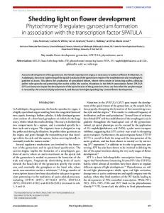
Figure 10: Illustration of the partition healing design objective. less, it is not uncommon that the operator of such a network still wants to implement efficient routing, i.e., router level shortest-path routing from any source to any destination across all branches of the network. BGP may appear to be a natural solution to connect the routing instances: Each office branch could be assigned a private BGP autonomous system (AS) number and the BGP protocol would allow routing information to be exchanged across them. The reality, however, is that BGP cannot support efficient routing in this setting. To illustrate the problem, we describe a network from the dataset. The network has three branches located respectively in North America, Europe, and Asia as shown in Figure 9. The network in North America is directly connected to the networks in Europe and Asia, which are also directly connected to each other. Suppose the operator has implemented a BGP solution to connect the three branches. Consider traffic from North America to Asia. There are two AS level paths to select from, one trans-Pacific and the other trans-Atlantic and transiting through the Europe network. If the operator has simply configured the BGP path selection policy to be first based on the length of the AS-PATH, the transPacific path with a single AS hop is always preferred. As a result, all traffic from North America to Asia will be forwarded using the trans-Pacific link. This is clearly not always efficient, especially for those traffic sources located on the East Coast of North America. To make an analogy, a traveler flying from North America to Bombay, India prefers flying across the Pacific ocean when leaving from the West coast. However, if departing from the East coast, the route through Europe is shorter. The operator may attempt to institute more sophisticated BGP policies by configuring BGP path attributes such as the Cisco proprietary Weight [6] attribute, and the standardized Local Preference (Local-Pref), Multi-Exit Discriminator (MED), and Community String attributes. Yet, no such policy is sufficient to ensure efficient routing at all times. Let us first explain the limitation of the Weight and Local-Pref attributes. These two attributes are designed to allow the operator to preempt the preference based on the AS-PATH length. However, they are set when a route is imported and by the domain that imports the route; as such, a path selection policy based on them cannot always adapt correctly to a change of path cost within an external domain. To illustrate this problem, consider the scenario where the operator has assigned a higher Local-Pref value to trans-Atlantic routes on the East Coast but a lower Local-Pref value to the same routes on the West Coast. Let us focus on traffic from an East Coast host “Sender 2” to an Asia host “Receiver”. Suppose that there are actually three distinct router-level paths from “Sender 2” to “Receiver”, labeled “Path 1”, “Path 2”, and “Path 3”, respectively, in Figure 9. Furthermore, suppose that the paths have end-to-end costs (distances) of 40, 50, and 60, respectively. The Local-Pref settings indeed enable BGP to
correctly choose “Path 1” over “Path 2” under normal conditions. However, when “Path 1” becomes unavailable (due to a network failure), traffic from Sender 2 will be incorrectly diverted to “Path 3” despite “Path 2” having a lower cost of (50 vs. 60). Additional configuration of the MED and/or Community String attributes cannot fully address the aforementioned limitation of BGP. While MED or Community String may be utilized in some cases to signal the router-level distance of a route to an external domain, the functionality is not general due to limitations of the iBGP protocol. (For brevity, a detailed explanation of the limitations is omitted.) Doing so would also introduce tremendous management complexity across the ASes. Finally, [21] provides further explanations regarding the limitations of the current BGP protocol in supporting efficient routing and proposes some extensions to the BGP protocol to address these limitations. In light of the drawbacks with BGP, it is no surprise that the operators decided to rely on route redistribution to achieve efficient routing across multiple routing instances. When redistributing a route from one IGP routing instance (e.g., an OSPF domain) directly to another instance of IGP, the cost of that route can be preserved. A router can then compute the global cost of the routes to each destination and select the shortest one. It should be noted that to avoid routing anomalies, the operators also had to carefully configure route redistributions with some handcrafted approaches, which will be discussed in Section 7.2.3.
6.2 Design objective B: partition healing Partition healing designates the ability for a network to provide reachability even in the event of a network partition [23]. Prior work also refers to this design objective as domain backup [14]. To illustrate the concept, consider a network with the “Example routing design” depicted in Figure 10. We focus on routers X and Y within routing instance 2. Because of one or multiple network failures, routing instance 2 may become partitioned into two separate networks with X in one partition and Y in the other. In such a situation, while X and Y can no longer directly communicate, a backup physical path exists for the two partitions to communicate through routing instance 1. However, if an operator relies on the BGP protocol to interconnect the two routing instances by assigning a private AS number to each instance, this backup route will not be discovered. This is because by default, an AS does not consider a BGP route when its AS number is present in the AS-PATH of that route. This behavior can be overridden but BGP then becomes vulnerable to forwarding loops. In addition to partition healing, operators want the capability to select the networks through which the recovering paths can traverse. Networks may request partition healing from their provider(s) but may not want it from their customer(s). Such preference is motivated by the financial relationships between the networks and re-
000000000000000000000000000000000000 111111111111111111111111111111111111 8% 92% 000000000000000000000000000000000000 111111111111111111111111111111111111 111111111111111111111111111111111111 000000000000000000000000000000000000
000000000000000000000000000000000000 111111111111111111111111111111111111 44% 56% 111111111111111111111111111111111111 000000000000000000000000000000000000 111111111111111111111111111111111111 000000000000000000000000000000000000 Simple RR
Simple RR Customized AD
Customized AD
Tag
8% 30%
4% 1% 2%
4%1%
Customized AD +Prefix Filter Customized AD +Tag
Customized AD +Tag
52%
55%
Tag
1%
42%
Tag+Prefix Filter
Tag+Prefix Filter
Customized AD +Tag+Prefix Filter
Customized AD +Tag+Prefix Filter
Figure 11: Complexity of the routing policies applied to route redistribution in networks that deploy the redistribute command.
Figure 12: Complexity of the routing policies applied to route redistribution in networks that deploy the redistribute command between IGP instances.
source constraints. Using a customer network as a transit network is likely to cause congestions in the customer network. Because of the inability of BGP to support partition healing, operators appear to rely on route redistribution to implement this functionality. The right part of Figure 10 describes a configuration pattern that we observed. It provides partition healing to different customer sites through a backbone network. For brevity, only one site (routing instance 2) is depicted. The sites are connected to the backbone (routing instance 1) through multiple redistribution points. Each border router redistributes only a single default route “0.0.0.0/0” from the backbone domain to the customer site. For the opposite direction, the border router redistributes every route except the default route. This configuration allows all sites to be reachable from each other. Since each site injects its internal routes into the backbone, the latter has routes to all the sites. When a host in one site sends data to a destination located in another site, the traffic will first enter the backbone network because of the advertised default route. The backbone then forwards the traffic to the destination. To illustrate the support for partition healing, we now assume that site 1 is partitioned into two parts with routers A and X on one side, and routers B and Y on the other. Router Y can no longer directly reach router X. However, having not received a route to X through the internal routing protocol, router Y forwards its traffic to B because of the advertised default route. Router B knows how to reach X thanks to router A which has received a route to router X and redistributed it into the backbone network. Consequently, the traffic reaches X through the Y -B-A-X path. We observed that this pattern is used not only between providers and customers but also between the sites of enterprises and university campuses.
sub optimal routing) documented recently [9], [15]. Router vendors have tried to mitigate this problem by publishing “remedy” templates for basic scenarios [9]. Second, operators may need to add even more options to support design objectives such as those shown in Section 6. We had also expected the route redistribution configurations to be diverse because the route redistribution feature was initially introduced as a software patch and there has been very little effort to standardize its usage.
7.
COMPLEXITY OF ROUTE REDISTRIBUTION
Sections 5 and 6 confirmed the first two hypotheses from Section 1: route redistribution is used widely in operational networks; and route redistribution is also used as a powerful tool for achieving important design objectives which cannot be achieved with routing protocols alone. In this section, we evaluate the third hypothesis: the route redistribution configurations in the wild are ad-hoc and complex. We had expected the route redistribution configurations to be complex. First, operators need to add safe guards against the routing anomalies (e.g., forwarding loops, route oscillations, and
7.1 Breaking down the complexity Most of the route redistribution configurations in the dataset are indeed complex. To break down the complexity of the configurations, we look at the routing policies that are applied to control the redistribution of the routes. We focus on the redistribute command4 , and the frequency of the three following methods applied to this command. • Tags: A tag can be assigned as an attribute to a route, based on which redistributed routes can be filtered or have their attributes (e.g., metric, next-hop, type) modified. • Prefix-filters: Prefix-filters provide the ability to apply routing policies to routes announcing a particular destination prefix. • Customized AD: Administrative distance (AD) defines the preference of a route. When a router receives multiple routes to the same prefix from multiple routing processes, it selects the route with the lowest AD value. The distance can be defined per-router, per-routing process and per-prefix. Figure 11 represents the presence of these three methods in all the routing policies applied to the redistribute command. 44% of the networks, that make use of the redistribute command, do not rely on any of these methods for its configuration. We refer to these route redistributions as “simple RR”. Vendors have released proprietary patches to prevent forwarding loops, sub-optimal routing and route oscillations when redistributing routes from BGP into OSPF 4
Policies can also be applied to the BGP network command which as explained in Section 5 provides another means to import routes into BGP. We focused on the redistribute command in this paper, and did not investigate the complexity of routing policies applied to the BGP network command. As will be shown, the observations with the redistribute command already highlight the high complexity of the route redistribution configurations.
and EIGRP [5], [7]. These extensions may be sufficient for these networks to fulfill their requirements. However, the majority of the networks – 56% of all networks employing the redistribute command – make use of tags, customized distances or prefix-filters to control the dissemination of the routing information across routing instances. In fact, most of the networks (88%) that implement routing policies not only use one method but use a combination of {tags, prefix-filters}, {prefix-filters, customized AD }, {tags, customized AD}, or rely on all three methods simultaneously. When concentrating on networks that depend on route redistribution to interconnect IGP domains, the fraction of the networks that deploy routing policies based on tags, prefix-filters or customized AD increases to 92% (Figure 12). This large number may stem from the high vulnerability of route redistribution when routes are exchanged among IGPs (e.g., from OSPF to EIGRP, etc.) [10]. Vendors’ safety extensions do not apply to redistributions between IGPs.
Y
C A
X
B
Z
M D
Site 2
Backbone
Site 1
N
Figure 13: Network topology to illustrate the potential instabilities. Z
Z
Y Y
Routing instance 3
C C D D
BGP 65000 (20/200)
Routing instance 1 OSPF (110)
Routing instance 2 OSPF (110)
Site 1
Routing instance 4 OSPF (110)
Backbone
Site 2
Figure 14: Routing instance interconnection graph of the network from Figure 13. (As explained in Section 3, the values in brackets represent the AD.)
7.2 Causes of the complexity The prevailing use of routing policies may be puzzling since vendors have released a number of proprietary extensions to prevent the formation of routing anomalies. Discussions with the operators reveal that the existing extensions are in fact insufficient to achieve safety in the network studied, and they implemented handcrafted solutions in order to achieve safety.
7.2.1 Potential instabilities caused by redistribution We first provide a brief description of the possible routing anomalies and the vendors’ patches. To illustrate the potential instabilities, we assume the topology depicted in Figure 13 whose routing instance interconnection graph is given in Figure 14. The topology is typical of the MPLS VPN architecture [20]. Routers Y , Z, A, B, C and D form a BGP backbone that connects the different sites, where A and B are route reflectors. Border routers Y and Z redistribute routes from Site 1 into the BGP backbone and viceversa. Similarly, border routers C and D connect Site 2 to the BGP backbone, and redistribute routes from the BGP backbone into Site 2 and vice-versa. Assume a prefix P is originated by X in Site 1. The following sequence of events illustrates the formation of a forwarding loop. t1 Y and Z learn a route to P from routing instance 1 and redistribute the route into routing instance 3 (BGP 65000). t2 The routes from Y and Z get propagated into routing instance 3 (BGP 65000). In particular, router C receives the announcements. C learns a route to P (with B as the next-hop) and redistributes it into routing instance 4. t3 D receives the OSPF advertisement from C. D may also receive the iBGP message from B. Because OSPF has a lower AD value (110) than iBGP (200), D selects the route from routing process 4, pointing to M as its next-hop and redistributes the route into routing process 3. t4 B now has two routes, one learned from A (which chooses one route from either Y or Z) and one from D. Suppose B’s BGP best path selection process chooses the route from D. B sends the route (with BGP next-hop being D) to C. C will still use B as the IGP next-hop in order to reach the BGP next-hop D. As a result, packets may loop between B-D-M -C-B. This is because a route is re-injected back into the routing instance where it came from.
[5], [20] provide a more detailed description of the above problem and illustrate other undesired consequences including route oscillations, and sub-optimal routing that can result from such a configuration.
7.2.2 Limitations of vendors’ solutions To prevent these instabilities from happening, some vendors have offered extensions [5], [7] to existing routing protocols. The extensions only apply in the context of VPNs and to routes redistributed from BGP into OSPF or EIGRP. Some bits in the headers of the OSPF Link State Advertisements or EIGRP route advertisement messages are used to indicate when routes are redistributed from BGP. These bits serve to notify that other border routers should discard the announcement. In the example above, when C redistributes the route to P from BGP into OSPF at t2 , the OSPF Link State Advertisement originated by C will have the bits set, informing router D to discard the received route. As such, the extensions prevent routing anomalies in simple scenarios. However, more complex topologies can still be vulnerable to routing instability. In this section, we report actual observations of real world networks where the limitations were manifested. We disclose two scenarios where the vendors’ solutions fall short, one previously reported in a hypothetical setting [22] and the other never reported before. Note that the scenarios below are exactly the same as the ones in Section 7.2.1 unless otherwise specified. Limitation 1 – Multi-origin routes: Discussions with operators highlighted that routes may be originated by multiple routing instances. Considering the network from Figure 13, P may not only be originated by routing instance 1 but also by some router N in routing instance 45 . The route announcement from N does not have the bit set in its header since it is not redistributed from the BGP domain. In such case, the advertisement from N appears valid to D. D now has two routes, one from routing instance 3, and one from N in routing instance 4 (the route redistributed by C is discarded due to set bits). It selects the route from N and point to M as its next-hop. However, because M is not a border router, it does not look at the bits in the advertisement. Thus it has two IGP routes: one redistributed from C and one from N . M will choose the route from C if the link weight of C-M is smaller than link weight of M -N , and choose C as the next-hop. Such scenario re5
For example, both sites 1 and 2 announce a default route.
Z
Z
Y Y
Routing instance 3
BGP 65000 (20/200)
Routing instance 1 OSPF (110)
Routing instance 2 OSPF (110)
Site 1
Backbone
C C D D OSPF (110)
Routing instance 4 Routing instance 5
F
OSPF (110)
Site 2
Figure 15: Limitations of vendors’ fixes when a site is comprised of multiple IGP instances. sults in a forwarding loop between B-D-M -C-B. To the best of our knowledge, this limitation has not been previously reported in the literature. Limitation 2 – Routes redistributed multiple times: [22] describes this risk. Suppose the scenario is the same as in Section 7.2.1, except that Site 2 consists of multiple IGP instances as illustrated in Figure 15. In such topology, when the route is redistributed from routing instance 4 into routing instance 5 (e.g., by F ), the bits in the packet header are cleared and D can therefore select the redistributed route. Then the forwarding loop B-D...F ...C-B is formed.
7.2.3 Handcrafted solutions and their limitations Because of the vulnerability of route redistribution to routing anomaly and the inadequacies of vendors extensions, operators have developed their own solutions. This section describes some of the methods operators have deployed. It is important to note that these solutions have been designed mainly based from experience. They have not been systematically validated and as such, their general effectiveness for preventing routing instabilities is largely unknown. Indeed, we show that some of these methods are still vulnerable to routing anomalies. In addition, the complexity of the configurations increases the chances for configuration errors. We describe prefix-based filtering solution that attempts to address Limitation 1, and routing instance trace solution that attempts to address Limitation 2. Prefix-based filtering Section 7.2.2 disclosed the potential formation of permanent forwarding loops for prefixes originating from multiple routing instances (Limitation 1). To prevent such anomaly, operators make use of filters and restrict the redistributions. To illustrate the solution, we consider the network from Figure 13 and we assume that P (e.g., the default route) is originated in all three routing instances 1, 3 and 4. In such case, prefix-filters would be deployed at the border routers (Y , Z, C, D) to only authorize the redistribution of routes to P in a unique direction. We now assume that the redistribution directions are from routing instance 3 into 1, and from 3 into 4. This method is tedious and error-prone since it requires the identification of the prefixes, the definition of the prefix-filters and the application of the filters at all the relevant border routers. More importantly, while this solution addresses the forwarding loop problem (Limitation 1), the network is still vulnerable to another routing anomaly: in the event of network failures, route oscillations can occur. Assuming that N fails, P is no longer originated in route instance 4 and we may obtain the following sequence of events: t1 Both routers C and D learn a route to P from routing instance 3, both redistribute their routes into routing instance 4 at the same time. t2 Router C receives the route redistributed by router D from rout-
ing instance 3 into routing instance 4. At the same time, router D receives the route redistributed by router C from routing instance 3 into routing instance 4. As such, C (resp., D) has two routes to P . The first one is received from routing instance 3 and the second one is received from routing instance 4. Because routing instance 4 has a lower AD, router C (resp., D) updates its entry to P and points to M as the next-hop. Both C and D stop redistributing a route to P into routing instance 4. t3 Router D (resp., C) no longer receives the route from C (resp., D). D (resp., C) only has one route to P which is received from routing instance 3. Therefore D (resp., C) updates its route to P , selecting the route from routing instance 3 and redistributes it into routing instance 4. We note that the states at t1 and t3 are identical. As such, the route oscillates between these states. [14] analyzed the origins of the anomalies in route redistribution and proposed a number of guidelines. To prevent these oscillations, the prefix-filters must be accompanied by an adjustment of the AD values at the border routers, such that 3 has a lower AD value than 1 and 4. With these modifications, when routers C and D receive two routes at time t2 , they will maintain their existing active route through routing instance 3. Routing instance trace Section 7.2.2 discussed the possible formation of permanent forwarding loops for prefixes that are redistributed across multiple IGP instances (Limitation 2). Networks that implement efficient routing through route redistribution as described in Section 6 can also result in transient forwarding loops. Although the cost of an OSPF route is preserved between OSPF routing instances and routers can compute the shortest path to every destination, forwarding loops can emerge. This is because when a route is redistributed into a target routing instance, this latter does not have a global view of the network but only knows the next routing instance where to forward the traffic. As such, the behavior is similar to that of a distance vector protocol and forwarding loops can form like in RIP (count to infinity problems) [15]. To avoid permanent and transient forwarding loops, some operators have implemented an interesting method which we call routing instance trace. BGP addresses forwarding loop problems through the AS-PATH where each BGP AS prepends its identifier when a route traverses a domain. This field allows an autonomous system to recognize routes it previously forwarded. As such, the BGP AS-PATH prevents routes from being re-injected back into an autonomous system where it initially came from. The same technique cannot be directly implemented in other routing protocols because contrary to BGP, IGP protocols (RIP, OSPF, EIGRP, etc.) typically support only a single fixed-length 32-bits tag per route. The routing instance trace approach keeps track of the routing instances traversed by a route through that 32-bits tag field: each routing instance is associated with a specific bit in the binary representation of the tag. For example, routing instance 1 may be assigned the right most bit of the tag. Whenever a route traverses a routing instance, its corresponding bit is flipped from 0 to 1. This method implements a trace that keeps track of the routing instances that have been traversed, similar to the AS-PATH in BGP. Networks therefore rely on the routing instance trace to prevent loops from occurring. The limitations of this method are that it requires a long and convoluted configuration at each border router, and that it does not scale to a large number of routing instances due to the limited number of bits in the available tag.
8.
DISCUSSION
Routing architecture Goal: select paths along which to send data
Section 8.1 discusses possible interpretations of the empirical results. Section 8.2 describes some limitations of this study.
rank
import
export
Routing protocols
Primitives Low−level operations allowing operators to construct more compound functions
Constraints/ coordination
Our data analysis results indicate that the use of route redistribution in operational networks is to a large extent due to the limitations of current routing protocols in meeting some design objectives (e.g., efficient routing and partition healing). A first interpretation of these results could be that existing routing protocols need to be extended or new routing protocols need to be defined to support the identified properties. However, this implies that every time a new operational need were identified, a new extension to the existing protocols or a new protocol would need to be created, which could be a very lengthy process. Such an approach would hamper innovations and the deployment of new services. This study shows that operators do not wait for new protocol extensions but “creatively” use whatever available tools to fulfill their objectives. As such, a more likely interpretation of the results seems that routing protocols may always need to be accompanied by some tools that leave enough flexibility in the architecture. As long as the Internet routing architecture is composed of multiple routing protocols, the glue logic is likely to remain and play a fundamental role. To illustrate this point, we draw an analogy between a set of routing protocols and a distributed database system. Each routing protocol can be viewed as one database offering a number of entries (i.e., routes). A router is a client that can access several databases at a time. The glue logic is the query interface that allows the client to compare the entries from different databases and to select the best entry for this specific client. Interestingly, this analogy illuminates a potential lack of flexibility of the current version of glue logic. The route selection and route redistribution procedures only allow operators to rank and select routes based on the administrative distance (AD) parameter. This rather simplistic logic might have severely limited the range of functionality that the glue logic can provide. For example, the efficient routing design pattern is currently only feasible between routing instances of the same routing protocol (e.g., between OSPF 1 and OSPF 2). However, an enterprise network may consist of multiple branches deploying different routing protocols. A branch in France may deploy RIP and rely on the metric attribute of a route to carry an indication of the physical distances in kilometers. Another branch which is in the U.K. may use the OSPF protocol and rely on the link cost to reflect the physical distance in miles. The current glue logic does not permit the operators to achieve efficient routing between the two branches through the following policy: “rank RIP routes based on RIP metric and OSPF routes based on 1.6 × OSPF cost.” As another example, it makes good sense from the traffic engineering perspective that some routes are advertised widely (e.g., from one AS to another via BGP) only if the available bandwidth for the corresponding data path exceeds a determined threshold. However, such a policy cannot be implemented using the current glue logic. In fact, as illustrated in Figure 16, we can identify three essential primitives of the glue logic, those of: 1) ranking of the routes from multiple routing processes, 2) importing of the routes from the routing protocols into the forwarding table and 3) exporting of the routes from the forwarding table into the routing protocols at each router. The existing primitives rely on the AD parameter. It would be a worthwhile exercise to consider alternative designs to add more flexibility to the glue logic. An extreme design point would be to add both the ability to manipulate based on additional criteria (e.g., metric, bandwidth, etc.) and the support of basic con-
Goal: disseminate routing information between RIBs
8.1 Interpretation of results
Glue logic Goal: rank routes, import routes from RIBs to FIB and export routes from FIB to RIBs
Figure 16: Main components of the routing architecture. structs (e.g., if condition, while loop, for loop). A step in this direction is taken in [4]. One may contest that adding flexibility to the glue logic may not always be desirable since it can be detrimental to routing safety. We argue that limiting the flexibility of glue logic is not an effective means to enhance routing safety. Section 7 showed that the existing glue logic, which is based on a single AD parameter, is already highly vulnerable to routing anomalies. Instead, efforts should be directed toward identifying sufficient conditions and associated configuration guidelines that are sufficient for ensuring routing safety and flexible enough to allow operators to achieve their desired objectives. [14] took a first step in this direction. We also envision the addition of a separate network-wide coordination mechanism to the glue logic to assure safety (Figure 16). The coordination mechanism would gather parameters related to the glue logic from all routers and make sure that collectively the parameters meet certain sufficient conditions for safety. The goal of the coordination mechanism is not to disseminate routing information, but to coordinate the actions at each router and to ensure that the workings of the glue logic at the different entities remain compliant with some global constraints. This functionality can be achieved by either enhancing the existing routing protocols (e.g., adding new attributes in routing updates) or deploying a new (centralized or distributed) coordination protocol, or some other mechanisms. Finally, there are ongoing efforts to redesign the Internet routing architecture [1], [24], [3]. We believe that the role of the glue logic should be closely examined in these studies.
8.2 Limitations of study The number of design patterns that can be discovered is ultimately constrained by the dataset and the methodology. The consideration of additional networks or other sources of information and the usage of alternative data mining methods may potentially reveal more operational design patterns. However, the goal of this study was not to identify all existing operational requirements, but to investigate whether the glue logic is used to implement important design objectives that cannot be achieved with existing routing protocols alone. We did not attempt to characterize the prevalence of the identified patterns (efficient routing and partition healing) in the dataset. Neither did we examine in depth the safety of the route redistribution configurations (e.g., determining the percentage of networks in the dataset that are vulnerable to routing anomalies). While such studies would be insightful, we sought to first better understand why and how operational networks use route redistribution. We disclosed some vulnerabilities of some configurations to illustrate the state of the art and the risk with current methods.
9.
RELATED WORK
A number of studies have looked at router configurations but for different purposes. For example, [11] and [12] parse configuration files to detect potential misconfigurations. This study is the first to look at the usage of route redistribution in operational networks. The closest related work is [17], which inferred routing design in operational networks from router configuration files. This study differs from [17] in several aspects. First, [17] concentrates on identifying the presence of the routing instances in a network, whereas this study focuses on the interconnections (i.e., the glue logic) between the routing instances. Second, the methodology in [17] does not consider a number of parameters that may impact the boundary of a routing instance and it does not model the AD value of a routing process, which is a critical parameter in determining a route’s eligibility to be redistributed. Third, [17] does not separately model the details of each interconnection point when two routing instances are interconnected at multiple border routers. These limitations of [17] restrain its ability to discover and infer the rationales of design patterns. Finally, in terms of results, while [17] revealed that the Internet landscape is more complex than a simple BGP/IGP hierarchy, this study has discovered two detailed routing design patterns driven by operational requirements that cannot be fulfilled by routing protocols alone. In terms of routing anomalies, [10], [9], [15], [14], and [16] illustrated possible undesired consequences that can result from route redistribution. Yet, [10] and [9] only addressed simple scenarios, and [15] and [14] relied on hypothetical configurations to illustrate potential instabilities. This paper is the first empirical look at the problem: we describe actual topologies and requirements to be met by operators, and we present some of the solutions currently used by operators. [21] proposes changes to BGP to support efficient routing. The proposed modifications allow routers to select more optimal paths than the current BGP path selection algorithm. Yet, they do not guarantee the selection of the shortest path. In addition, [21] only addresses one requirement but not the other design objectives (e.g., partition healing) that our study disclosed. Finally, to address the shortcomings of existing routing protocols, [13] introduces an elegant framework for operators to implement their own routing protocols. Yet, whether the identified operational requirements can be supported by such protocols still needs to be investigated.
11. ACKNOWLEDGMENTS We thank Jay Borkenhagen, Appanna Chottera, Mike Donoghue, Alex Gerber, Timothy Griffin, Seungjoon Lee, Steve Legget, Mark Lyn, Kobus van der Merwe, Jason Philippon, Mike Satterlee, Tom Scholl, Aman Shaikh and Philip Taylor for many helpful discussions. We would also like to express our gratitude to all others who provided us with the configurations of their networks and discussed them with us but prefer to preserve their anonymity. This research was partially sponsored by the NSF under the 100x100 Clean Slate Project [1] (NSF-0331653), the 4D Project [2] (NSF-0520187), grants CNS-0520210, CNS-0721574 and a Graduate Research Fellowship. Views and conclusions contained in this document are those of the authors and should not be interpreted as representing the official policies, either expressed or implied, of AT&T, NSF, or the U.S. government.
12. REFERENCES [1] [2] [3] [4] [5] [6] [7] [8] [9] [10] [11]
[12]
[13] [14] [15] [16]
10. CONCLUSION By examining operational network configurations, this paper has brought to light the critical role played by the “hidden” glue logic between the routing protocols. This study confirmed the prevalence of route redistribution in operational environments. More importantly, it showed that operators rely on it not simply to interconnect routing instances but also to implement design objectives beyond simple exchange of routes. These discoveries expose some major insufficiencies of existing routing protocols to support operational requirements. The study also found that the high vulnerability of route redistribution to routing anomalies has resulted in complex configurations. Furthermore, some of the complex configurations can still be vulnerable to routing instabilities. These empirical results seem to strongly suggest that making routing protocols safe and robust alone may not be sufficient to ensure robustness of a network. This observation underscores the urgency for more efforts by both the research and operational communities to address all documented safety problems of the glue logic. Finally, we believe that the evolution of the glue logic role in the Internet architecture consitutes an exciting area for future research.
[17]
[18] [19] [20] [21] [22]
[23] [24]
100x100 Clean Slate Project. www.100x100network.org. 4D Project. www.cs.cmu.edu/∼4D. NSF FIND Program. www.nets-find.net. XORP. www.xorp.org. Cisco. Using OSPF in an MPLS VPN Environment, 2002. Cisco. BGP Best Path Selection Algorithm, 2006. Cisco. EIGRP MPLS VPN PE-CE Site of Origin, 2006. Cisco. OSPF Design Guide, 2006. Cisco. OSPF Redistribution Among Different OSPF Processes, 2006. Cisco. Redistributing Routing Protocols, 2006. N. Feamster and H. Balakrishnan. Detecting BGP Configuration Faults with Static Analysis. In Proc. NSDI, 2005. A. Feldmann and J. Rexford. IP Network Configuration for Intradomain Traffic Engineering. In IEEE Network Magazine, 2001. T. G. Griffin and J. L. Sobrinho. Metarouting. In Proc. ACM SIGCOMM, 2005. F. Le and G. Xie. On Guidelines for Safe Route Redistributions. In Proc. ACM INM Workshop, 2007. F. Le, G. Xie, and H. Zhang. Understanding Route Redistribution. In Proc. IEEE ICNP, 2007. F. Le, G. Xie, and H. Zhang. Instability Free routing: Beyond One Protocol Instance. Technical Report CMU-CS-08-123, May 2008. D. Maltz, G. Xie, J. Zhan, H. Zhang, G. Hjalmtysson, and A. Greenberg. Routing design in operational networks: A look from the inside. In Proc. ACM SIGCOMM, 2004. S. Misel. Wow, AS7007! www.merit.edu/mail.archives/ nanog/1997-04/msg00340.html. V. Paxson. End-to-end routing behavior in the Internet. In Proc. of ACM SIGCOMM, 1996. I. Pepelnjak and J. Guichard. MPLS and VPN Architectures. Cisco Press, 2000. Ratul Mahajan et al. Mutually Controlled Routing with Independent ISPs. In Proc. NSDI, 2007. E. Rosen, P. Psenak, and P. Pillay-Esnault. OSPF as the Provider/Customer Edge Protocol for BGP/MPLS IP Virtual Private Networks (VPNs). RFC 4577, 2006. J. W. Stewart. BGPv4: Inter-Domain Routing in the Internet. By Addison-Wesley, 1999. T. V. Lakshman et al. The SoftRouter architecture. In Proc. ACM HotNets Workshop, 2004.