TEMC-091-2018
1
Shielding Effectiveness and HPM Vulnerability of Energy-saving Windows and Window Panes Per Ängskog, Senior Member, IEEE, Mats Bäckström, Senior Member, IEEE, Carl Samuelsson, and Bengt Kangashaka Vallhagen, Member, IEEE
Abstract—In the present work we report results from shielding effectiveness measurements on energy saving windows and individual, coated window panes of different generations, as well as results from high power microwave irradiation on single panes. Shielding effectiveness was measured with two complementary methods; one with near isotropic irradiation in nested reverberation chambers, and the other with irradiation at normal-incidence in a semi-anechoic chamber. The measurements show that the construction of the energy conserving windows has a clear impact on how well they attenuate radio frequency signals. The more modern the window or pane, the higher is the shielding effectiveness. The high power irradiation on coated panes showed that, depending on type of coating, hot-spots can build up causing the coating to crack and hence deteriorate the shielding effectiveness. These results may serve as guidance when reviewing EMP, High Power Microwave, or Intentional Electromagnetic Interference protection of critical infrastructures and as assistance in the work with reduction of compromising emanations. Index Terms— Shielding Effectiveness; HPM; IEMI; compromising emanations; Energy saving windows; Coated window panes.
A
I. INTRODUCTION
time as the dependency on electrical and electronic systems increases in our society, intentional electromagnetic interference (IEMI) is becoming a potent threat readily available for perpetrators ranging from lay-men to terrorists [1]-[3]. These systems, when in critical infrastructures, such as financial functions; supply of water, food, fuel and electricity; and transportation etc. strikingly often have their automation, control and communication systems based on commercial-off-the-shelf (COTS) equipment T THE SAME
This work was financially supported by the Swedish Civil Contingencies Agency (MSB) and headed by The Swedish Fortifications Agency. P. Ängskog is with KTH - Royal Institute of Technology, Dept. of Electromagnetic Engineering, Stockholm, Sweden and University of Gävle, Dept. of Electronics, Mathematics and Natural Sciences, Gävle, Sweden (email:
[email protected]). M. Bäckström is with KTH - Royal Institute of Technology, Dept. of Electromagnetic Engineering, Stockholm, Sweden and Saab Aeronautics, Linköping, Sweden, (e-mail:
[email protected]). C. Samuelsson is with Saab Aeronautics, Linköping, Sweden, (e-mail:
[email protected]). B. Kangashaka Vallhagen is with Saab Aeronautics, Linköping, Sweden, (e-mail:
[email protected]).
which usually do not have higher protection levels than what is prescribed in the basic civil EMC regulations. IEMI attacks have already been reported from various places in the world [4]. Hence it is essential that the awareness of IEMI as a threat is recognized and protective measures taken. Apart from keeping the perpetrator at a large enough distance, the attenuation of the building itself is one of the most important passive protection methods. The importance of the intrinsic attenuation of a building (a.k.a. shielding effectiveness, SE) and how to measure it has been studied in [5] and [6]. In the light of recent development of a highattenuating construction material, the Intelligent Concrete® [7], focus naturally turns to the apertures in the building wall. Previously, the window has been considered being one of the weakest links in building protection against electromagnetic interference. This is true if considering uncoated float-glass as is done in [8] where a window in practice did not exhibit more than half a dB or so in attenuation. However, recent studies have shown that modern coated windows intended to save energy by reducing propagation of infra-red and ultra-violet light also can attenuate signals in the radio and microwave spectrum. Attenuations high enough to make mobile communication impossible from indoors have been reported, e.g. in [9]-[10], and in one reported case an even higher building attenuation was obtained after removing a piece of a brick wall and installing a modern window [11]. This radio attenuation is partly seen as a problem that needs to be eliminated and for example attempts are made to reduce the attenuation using frequency selective structures [12]. However, in this paper the focus is on taking advantage of the increased attenuation for IEMI protection. There are also benefits to be gained in the other direction, in terms of less information leakage (so called compromising emanations or TEMPEST), due to the reduced electromagnetic radiation out from buildings. It can be assumed that as the energy-saving efficiency increases so does the SE. Hence, generation dependence in SE should be present for individual window panes as well as for complete window units. With the purpose to investigate this, a series of measurements on samples of different generations has been carried out. In parallel, theoretical studies on the radio-wave propagation behavior through coated glass have been published [13]. As high power microwave (HPM) sources are likely to be part of the arsenal of a potential attacker the ability to
TEMC-091-2018
2
withstand such irradiation is of high interest. The impact of HPM irradiation on the shielding effectiveness of individual window panes has been briefly reported in [14], this is also discussed in this article. Over the last few years a number of multinational projects sponsored by the European Union [15], in parallel with national projects in Switzerland and Sweden, have been executed in Europe focusing on various aspects of IEMI. The work presented in this paper is emanating from the Swedish project “Protection against Electromagnetic Risks. Intentional Electromagnetic Interference (IEMI)”. The findings herein are based on studies the authors have conducted at the EMC Laboratory at Saab Aeronautics in Linköping, Sweden. II. EXPERIMENTAL METHOD Shielding effectiveness can be measured in different ways. In a laboratory environment it can be measured in an anechoic or semi-anechoic chamber (SAC) with radiation incident from various angles, or it can be measured under almost isotropic conditions using nested reverberation chambers (RC). Since the methods are complementary we have used both methods in our studies. For both methods our measurements cover the frequency range 1-18 GHz. A few of the window panes were also tested for HPM irradiation effects an L-band frequency (1.3 GHz), with the field strength 28 kV/m, at the Swedish MTF range in Linköping. A. Shielding Effectiveness Measurements in a Nested Reverberation Chamber Using nested reverberation chambers the SE measurements can be conducted under virtually isotropic conditions. In an isotropic environment all incident angles and all polarizations do exist at the same time. In practice, this can be achieved using an RC with asymmetrical stirrers that change the boundary conditions of the chamber. The measurements are then carried out using a sufficiently large number of uncorrelated stirrer positions to achieve a high degree of isotropy. The principles of the method have been described and developed in [16]-[18]. 1) Isotropic Aperture Transmission Cross Section The immediate result from the RC measurements is not the SE but rather what is called the isotropic transmission cross section of the measurement sample, denoted 〈𝜎𝜎𝑎𝑎 〉1. The brackets around 〈𝜎𝜎𝑎𝑎 〉 indicates that it has been acquired under isotropic conditions. In [16] we can find that 𝜎𝜎𝑎𝑎 under plane wave conditions is defined as: 𝑃𝑃𝑡𝑡𝑡𝑡𝑡𝑡𝑡𝑡𝑡𝑡 = 𝜎𝜎𝑎𝑎 (𝜃𝜃, 𝜙𝜙, 𝑝𝑝) ∙ 𝑆𝑆𝑖𝑖𝑖𝑖𝑖𝑖 (𝜃𝜃, 𝜙𝜙, 𝑝𝑝),
(1)
where 𝑃𝑃𝑡𝑡𝑡𝑡𝑡𝑡𝑡𝑡𝑡𝑡 is the power transmitted through the aperture, Sinc is the power density of the incident field, and 𝜃𝜃 and 𝜙𝜙 indicate the angle of incidence of the plane wave while p is 1 Note that the definition of 〈𝜎𝜎𝑎𝑎 〉 and 〈𝜎𝜎𝑡𝑡 〉 in [17] for historical reasons differs by a factor of 2, i.e. 〈𝜎𝜎𝑡𝑡 〉 =2〈𝜎𝜎𝑎𝑎 〉.
the polarization. Equation (1) translates into the following when under isotropic conditions: 𝑃𝑃𝑡𝑡𝑡𝑡𝑡𝑡𝑡𝑡𝑡𝑡 = 〈𝜎𝜎𝑎𝑎 〉 ∙ 𝑆𝑆𝑠𝑠𝑠𝑠,𝑅𝑅𝑅𝑅𝑅𝑅 .
(2)
〈𝜎𝜎𝑎𝑎 〉 denotes the isotropic transmission cross section. i.e. 〈𝜎𝜎𝑎𝑎 〉 corresponds to the average of the 〈𝜎𝜎𝑎𝑎 〉 over all angles and polarizations. 𝑆𝑆𝑠𝑠𝑠𝑠,𝑅𝑅𝑅𝑅𝑅𝑅 represents the scalar power density inside the RC, a concept introduced in [17]. The isotropic transmission cross section 〈𝜎𝜎𝑎𝑎 〉, cf [17], can be used in the calculation of the average isotropic shielding effectiveness 〈𝑆𝑆𝑆𝑆〉 of nested overmoded cavities, i.e. of the nested cavity “behind” the aperture, using: 〈𝑆𝑆𝑆𝑆〉 =
𝑆𝑆𝑠𝑠𝑠𝑠,𝑅𝑅𝑅𝑅𝑅𝑅 𝑆𝑆𝑠𝑠𝑠𝑠,𝑐𝑐𝑐𝑐𝑐𝑐
2𝜋𝜋∙𝑉𝑉
= 〈𝜎𝜎
𝑎𝑎 〉∙𝜆𝜆∙𝑄𝑄
.
(3)
V is the volume of the cavity, λ the wavelength, 𝑆𝑆𝑠𝑠𝑠𝑠,𝑐𝑐𝑐𝑐𝑐𝑐 is the scalar power density of the field inside the cavity, and Q denotes the quality factor of the cavity. It is noteworthy that the 〈𝑆𝑆𝑆𝑆〉 is not only depending of the aperture under test but also the volume and Q-value of the cavity. This means that by determining the Q-value of the nested chamber 〈𝜎𝜎𝑎𝑎 〉 can be derived. Another, rather more practical procedure is to relate the 𝑆𝑆21,𝐴𝐴𝐴𝐴𝐴𝐴 measured (using the VNA) for the aperture under test (AUT) to a reference measurement of 𝑆𝑆21,𝑟𝑟𝑟𝑟𝑟𝑟 of the isotropic transmission cross section of a circular aperture 〈𝜎𝜎𝑎𝑎,𝑟𝑟𝑟𝑟𝑟𝑟 〉 for which a numerical solution has been derived [19]. In our reference measurements we have thus measured 𝑆𝑆21 through a circular reference aperture of 30 mm diameter, mounted in a 2 mm thick, 300x300 mm2, aluminum plate. Thus solved for 〈𝜎𝜎𝑎𝑎,𝑟𝑟𝑟𝑟𝑟𝑟 〉, 〈𝜎𝜎𝑎𝑎,𝐴𝐴𝐴𝐴𝐴𝐴 〉 is then easily acquired using the quotient between 𝑆𝑆21,𝐴𝐴𝐴𝐴𝐴𝐴 and 𝑆𝑆21,𝑟𝑟𝑟𝑟𝑟𝑟 according to [20]: 〈σa,AUT 〉 = 〈
S2 21,AUT S2 21,ref
〉 ∙ 〈σa,ref 〉.
(4)
Inside both chambers rotating stirrers are installed, a.k.a. mode stirrers. The stirrer in the main chamber is stepped in 21 positions and for each of these positions the stirrer in the nested chamber steps through another 12 positions, all in all 252 combinations of uncorrelated mode stirrer positions. The accuracy in the measurement of 〈𝜎𝜎𝑎𝑎 〉 depends on the number of uncorrelated samples in the test, [21, 22]. From the number of stirrer positions this gives a method uncertainty of 〈𝜎𝜎𝑎𝑎 〉, at each frequency, of around ± 3.5 dB. Since this value is much larger than that associated with the measurement uncertainty itself (typically < ±0.2 dB) we conclude that the RSS (root sum square) uncertainty in a measurement of 〈𝜎𝜎𝑎𝑎 〉 is around ±3.5 dB. Furthermore, for the measurements presented in the figures below we have used a moving average over 21 frequency points. This means that the uncertainty of 〈𝜎𝜎𝑎𝑎 〉 in those plots is about ±0.8 dB.
TEMC-091-2018
3
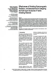
Fig. 1 A measurement sample being mounted over the 300 mm by 300 mm aperture on the internal, nested, chamber. The fixing frame, to the right, is tightened firmly with 16 wing nuts and two conductive gaskets, one underneath and one on top of the sample.
Regarding systematic errors, the method assumes that the cavity Q-value does not exhibit noticeable variations between the reference measurement and the AUT measurement. Under our conditions, this implies that 〈𝜎𝜎𝑎𝑎 〉 for the AUT must not exceed -32 dBm2; i.e. that 〈𝑆𝑆𝑆𝑆〉 must be greater than 15 dB in order to achieve a systematic uncertainty less than 1 dB. In order to facilitate comparisons with SE measured at normal incidence (cf. section B, below) the set-up used in the present case includes a square reference aperture measuring 300 x 300 mm2 cf. Fig. 1. This simple geometry makes it possible to express the result above, for isotropic conditions, in terms of shielding effectiveness, simply by comparing the power transmitted through the unshielded square aperture with the power transmitted through the aperture when the shielded structure is mounted on it, i.e.: 𝐴𝐴⁄4
𝑆𝑆𝑆𝑆𝑎𝑎𝑎𝑎𝑎𝑎𝑎𝑎𝑎𝑎,𝑖𝑖𝑖𝑖𝑖𝑖 = 〈𝜎𝜎
𝑎𝑎 〉
.
(5)
In this way we can, in a rational way, compare 𝑆𝑆𝑆𝑆𝑎𝑎𝑎𝑎𝑎𝑎𝑎𝑎𝑎𝑎,𝑖𝑖𝑖𝑖𝑖𝑖 with SE from measurements using normal incidence, i.e. with the 𝑆𝑆𝑆𝑆𝑎𝑎𝑎𝑎𝑎𝑎𝑎𝑎𝑎𝑎,𝑆𝑆𝑆𝑆𝑆𝑆 in (6). The isotropic conditions in the RC imply that the transmission cross section is equal to A/4, [16][17]; this is why the open square aperture is divided by 4. A cosine dependence of the transmitted power [17] comes from the irradiation from all angles (from normal to grazing angles) which is the root of one factor of two. The second factor of two stems from the half sphere irradiation of the aperture since the field in the RC is measured far away from the walls. 2) Measurement Set-up The 〈𝑆𝑆𝑆𝑆〉 measurements are performed using nested reverberation chambers according to Fig. 2. The set-up includes a smaller, approximately 1 m3 (1.53 x 0.93 x 0.69 m3), internal, RC within the main RC. The chambers are nested through a 300 x 300 mm2 square shaped aperture where the measurement samples are mounted. The aperture has a 50 mm flange with stud screws along all sides, Fig. 1. In the measurement procedure transmission is measured as scattering parameters (s-parameters) with a vector network analyzer (Rohde & Schwarz ZVA 40) connected to the
Fig. 2. Simplified block diagram showing the measurement set-up in the reverberation chamber measurements.
transmitter antenna inside the outer cavity (the main chamber) and to the receiver antenna inside the internal cavity (the nested chamber). Measurements are conducted over the range 1-18 GHz using a logarithmic sweep with 1601 frequency points, i.e. the measurements are distributed logarithmically over the frequency range. An extra receiver antenna is used to monitor the environment in the main chamber; all antennas used are double ridged horn antennas, ETS Lindgren 3115, with frequency range 0.75-18 GHz . B. Shielding Effectiveness Measurements in Semi-anechoic Chamber In the SAC the shielding effectiveness is determined by letting a wave illuminate the measurement sample at a fixed angle of incidence (see Fig. 3). According to common practice a comparative method is used, where the transmission loss is measured between two antennas before and after the measurement sample is mounted over the open square aperture, a.k.a. the “hatch on/hatch off” method. These measurements may be repeated for a desired number of incident angles and polarizations. The shielding effectiveness of the test aperture, 𝑆𝑆𝑆𝑆𝑎𝑎𝑎𝑎𝑎𝑎𝑎𝑎𝑎𝑎,𝑆𝑆𝑆𝑆𝑆𝑆 , is given by: 𝑆𝑆𝑆𝑆𝑎𝑎𝑎𝑎𝑎𝑎𝑎𝑎𝑎𝑎,𝑆𝑆𝑆𝑆𝑆𝑆 =
𝑃𝑃𝑡𝑡𝑡𝑡𝑡𝑡𝑡𝑡𝑡𝑡,𝑟𝑟𝑟𝑟𝑟𝑟
𝑃𝑃𝑡𝑡𝑡𝑡𝑡𝑡𝑡𝑡𝑡𝑡,𝑎𝑎𝑎𝑎𝑎𝑎𝑎𝑎𝑎𝑎
,
(6)
where 𝑃𝑃𝑡𝑡𝑡𝑡𝑡𝑡𝑡𝑡𝑡𝑡,𝑟𝑟𝑟𝑟𝑟𝑟 denotes the power received in the reference case and 𝑃𝑃𝑡𝑡𝑡𝑡𝑡𝑡𝑡𝑡𝑡𝑡,𝑎𝑎𝑎𝑎𝑎𝑎𝑎𝑎𝑎𝑎 denotes the power received when the glass sample is mounted on the test panel. This 𝑆𝑆𝑆𝑆𝑎𝑎𝑎𝑎𝑎𝑎𝑎𝑎𝑎𝑎,𝑆𝑆𝑆𝑆𝑆𝑆 may now be directly compared with the 𝑆𝑆𝑆𝑆𝑎𝑎𝑎𝑎𝑎𝑎𝑎𝑎𝑎𝑎,𝑖𝑖𝑖𝑖𝑖𝑖 acquired according to (5). 1) Measurement Set-up The measurement sample is mounted over an aperture sized 300 by 300 mm2 in a wall between the control room and the anechoic chamber. The transmit and receive ETS Lindgren 3115 horn antennas are mounted on either side of the aperture at 300 mm distance from the measurement sample. Antennas are oriented for normal incidence and adjusted for either horizontal or vertical polarization. The aperture has a metal frame against which the samples are pressed, sealed with conductive gaskets in the same way as on the nested chamber
TEMC-091-2018
4 -
-
Fig. 3. Block diagram showing the set-up used during the measurements in the SAC.
flange in the RC measurements. The measurements in the SAC are conducted over the range 1-18 GHz using a vector network analyzer, HP 8720, set for a logarithmic sweep with 1601 frequency points just as in the RC case. C. High Power Microwave Irradiation and Shielding Effectiveness Measurements The high power effects are determined using a “before/after” (comparative) three-step test method. First, as a reference, SE is measured in the RC before the high power irradiation. In the second step, the sample under test is exposed to HPM irradiation. Thirdly, after the irradiation, the SE is re-measured and a comparison is made to reveal any effects of the high power irradiation. The HPM exposure was conducted at the FMV Microwave Test Facility (MTF) located at Saab Aeronautics in Linköping, Sweden, [23]. At the facility the samples were subjected to 5 µs-long pulses with 390 Hz pulse repetition frequency during a 10 second HPM burst at 28 kV/m on 1.3 GHz (i.e. in the L-band). III. MEASUREMENT SAMPLES The samples tested were in two groups, i) single window panes, three different modern window panes with different energy saving coatings, presented in Table I, and three special panes, mainly used in public buildings, presented in Table II, and ii) four energy saving windows, without sash and frame, representing four generations of windows, presented in Table III. TABLE I
MEASUREMENT SAMPLES – SINGLE WINDOW PANES, STANDARD TYPES. Specimen name Construction Planibel G fas T ‘Hard Coated’ Low-emission Glass Planitherm Ultra II ‘Soft Coated’ Glass 1 Silver Layer Cool Lite SKN165 ‘Soft Coated’ Glass 2 Silver Layers
-
Planibel G Fas T is a type of glass called hard coated glass. The coating, a few hundred nanometer of SiO2, is burnt into the surface using pyrolysis (known as chemical vapor deposition, CVD); the coating is a transparent conductive oxide, TCO.
Planitherm Ultra II is what is referred to as soft coated glass, coated with two layers of metal-oxide (e.g. SiO2) interleaved with a thin layer of silver, approximately 10 nm thick. The coating is deposited on the glass using physical vapor deposition, PVD. CoolLite SKN 165 is a soft coated glass as well, however, there are two silver layers sandwiched between the metal-oxide layers. Also here the coating is deposited on the glass using PVD.
TABLE II MEASUREMENT SAMPLES – SINGLE WINDOW PANES, SPECIAL TYPES. Specimen name Construction Cool Lite SS132 Coated Solar-Control Spandrel Glass Priva-Lite Classic Diamant Electrically Controlled Privacy Glass E-Glass Stadip TCO Glass (Warm Glass)
-
-
-
The CoolLite SS132 is a, so called, spandrel glass, an opaque glass used to hide construction elements that would otherwise be visible through an all glass façade. Priva-Lite is a laminated glass constructed as a twopane sandwich with a liquid-crystal film (with two electrical terminals connected to it) in between. The glass is translucent until a voltage is applied across its terminals, makes it become transparent. The E-Glas Stadip is referred to as “Warm glass”, based on a TCO-coating. The coating has a defined electrical resistance from side to side of the pane, over which a voltage is applied. Its use is as an integrated heating solution for large glass façades that provides anti-condensation, snow melting, and heating.
The construction of window panes and the coating process has been described in more detail in [14]. The windows are thermally insulating units using the vacuum flask principle to prevent energy to propagate through them. TABLE III MEASUREMENT SAMPLES – COMPLETE WINDOW UNITS (WITHOUT SASH). Specimen name Construction D4-15 Double-glazed Energy saving window T4-15 Triple-glazed Energy saving window T4-Ultra Triple-glazed Low-emission window T4-2xUltra Triple-glazed Ultra-low e-glass
-
-
D4-15 is a window with two float-glass panes, 4 mm thick, separated 15 mm (4–15–4) resulting in a volume that typically is filled with dry air. T4-15 is similar to the D4-15 with the main difference being three panes instead of two in a 4–15–4–15–4 configuration with dry air in the two cavities. T4-Ultra is also triple glazed with the two cavities filled with Argon gas which has higher thermal resistance, and one coated Planitherm Ultra II pane. T4-2xUltra is similar to T4-Ultra with the difference that two of the panes are Planitherm Ultra II.
TEMC-091-2018
Fig. 4. Results comparing the isotropic measurements of shielding effectiveness, SEapert,iso, in the Reverberation chamber, for window panes. From top to bottom: i) Cool Lite SKN165, ii) Planitherm Ultra II, iii) Planibel G fas T, iv) E-Glas, v) Priva-Lite, and vi) Spandrel, Cool Lite SS132.
Fig. 5. Results comparing the measurements of shielding effectiveness, SEapert,SAC, in the SAC, for window panes. From top to bottom: i) Cool Lite SKN165, ii) Planitherm Ultra II, and iii) Planibel G fas T.
IV. RESULTS AND DISCUSSION Shielding effectiveness has been measured for six different types of window panes and four window units of different generations over the band 1-18 GHz. Most window panes and window units were measured both in a semi-anechoic chamber, and in nested reverberation chambers. As will be shown below, clear generational differences were observed, where not only the number of coating layers but also the type of coating influence the attenuation of radio and microwave radiation. Four of the panes were also subjected to pulsed high power microwave irradiation to study possible heating effects, revealing a notable difference in sensitivity to HPM exposure between different types of samples. A. Shielding Effectiveness of Window Panes In Fig. 4 and Fig. 5 we can see that the shielding effectiveness magnitude for standard panes, c.f. Table I, measured in the RC and the SAC respectively, correlate well between the respective sample types (In all figures the plots are smoothed over a 1.3% frequency span for improved
5
Fig. 6. Results comparing the isotropic measurements of shielding effectiveness, SEapert,iso, in the RC, windows. Above: T4-2xUltra, below: T4Ultra.
Fig. 7. Results comparing the measurements of shielding effectiveness, SEapert,SAC, in the SAC for windows. From top to bottom: i) T4-2xUltra, ii) T4-Ultra, iii) T4-15, and D4-15.
readability). The large local variations in SE over frequency in Fig. 5 are expected since the measurements in the SAC and in the RC are conducted under different circumstances. The traces plotted in Fig. 4 stem from the RC measurements where the SEapert,iso is calculated from the measured 〈𝜎𝜎𝑎𝑎 〉, according to (5). As this method creates an average SE over all incident angles and polarizations, the SEapert,iso trace is having less pronounced variations over frequency. In contrast, as shown in Fig. 5, the results of an electromagnetic wave striking the test object at one fixed angle of incidence with one single polarization according to (6) gives strong variations in SEapert,SAC magnitude over frequency. At normal incidence no significant difference in SE could be observed when changing the polarization between vertical and horizontal. Our measurements have shown clear generation dependence between different coatings on window panes. From trace iii) the hard coated Planibel G fas T with around 20 dB SE, via trace ii) the soft coated (1 silver layer) Planitherm Ultra II with 25 dB to i) the soft coated (2 silver layers) CoolLite SKN165 reaching around 35 dB SEapert,iso. As a comparison traditional clear float-glass would not give more than a couple of dB SEapert,iso in the same frequency range, [8] and [14].
TEMC-091-2018 Fig. 4 also contains the three special glasses from Table II; it can be noted that the warm glass (E-Glass Stadip), trace iv) lies just around the Planibel G glass, which is quite reasonable since both are TCO coated. The small variations in magnitude and shape are explained by the choice of different metal oxide depending on the performance requirements for the respective type. A peculiarity is the up to 7 dB increased SEapert,iso at frequencies above 6-7 GHz for the warm glass (iv) and the privacy glass (v). This behavior was independent of whether the sample was powered (activated) or not. Apart from generation dependence we have also shown that measuring isotropic transmission cross section, 〈𝜎𝜎𝑎𝑎 〉, under isotropic conditions in a nested reverberation chamber can reveal issues, i.e. side leakage, that are impossible to detect immediately when measuring the shielding effectiveness, SE, at normal incidence in the SAC. B. Shielding Effectiveness of Windows The results from the RC measurements, as seen in Fig. 6 correspond reasonably well with the results from the SAC, shown in Fig. 7. Although, not with as clear correspondence as between the panes in Fig. 4 and 5. The attenuation through D4-15 and T4-15 is too low to for isotropic measurements and is hence not measured in RC and thus not presented in Fig. 6. It can be seen though, that the attenuation of the windows follows the addition of more panes (D4 → T4), and the introduction of coated panes (T4 → T4_Ultra → T4_2xUltra); each type representing a new, more energy efficient generation of windows, also introducing more radio attenuation, i.e. higher SE. In the window unit case the effects of grazing incident angles are evident. To minimize the side-leakage caused by incident waves at grazing angles in the RC, the sides of the window units were sealed with copper-tape. Even though this precaution was taken, effects of leakage were observed – probably because it is extremely difficult to achieve good electrical contact between the nm thick edges of the coatings and the copper taping on the window unit sides. This is thought to be the main reason why the SE obtained in the RC frequently is (slightly) lower than that measured in the SAC. This side-leakage is supposed to be the main reason why the SE traces of windows and panes do not resemble as much as would otherwise be expected. This also gives a good illustration of the difficulty with the SAC measurement method; if having only a limited number of incident angles and polarizations (in our case only normal incidence) anomalies are easily missed. An additional cause for these deviations between panes and window modules could be the reflection behavior in multilayer structures described in [13]; this effect will increase with the number of panes the wave has to propagate through, and their respective coating. Also for windows it is possible to identify clear generation dependence with respect to SE; where the most modern types may give a SE of on average 20 to 30 dB, reaching as high as 50 to 60 dB, for normal incidence, in the upper part of the measured frequency range, while a traditional energy saving window with two or three float-glass panes only gives a few
6 dB [14]. C. The Effects on Shielding Effectiveness of High-Power Microwave Irradiation After the HPM irradiation the panes were first checked visually for changes and then re-measured in the RC to detect changes in the SEapert,iso. Two samples, the hard-coated (Planibel G fas T) and the spandrel glass (Cool Lite SS132) did not show any visual effects from the high-power exposure. While, in contrast, the two silver-coated samples, Planitherm Ultra II and Cool Lite SKN165 were clearly affected by the irradiation. The effects were cracks in the coating, visible to the naked eye, c.f. Fig 8. The Lichtenberg-like shape of cracks indicates that the strong electric field caused thermal stress and break-down in local hot-spots. The visually undamaged samples did not reveal any detectable changes in SEapert,iso, while both of the panes with visual cracks exhibited SEapert,iso deterioration ranging from 5 to 15 dB as can be seen in Fig. 9. Thus it was observed that the effects on SEapert,iso between panes follows the type of coating they are equipped with, and this also determines the capability to withstand high-power irradiation without thermal break-down, where PVD-coated
Fig. 8. Results from irradiating the double-layered silver-coated CoolLite SKN165 with HPM pulses in the MTF, note the cracks in the coating in the upper right corner.
Fig. 9. Comparing the shielding effectiveness measured on the double-layer silver-coated Cool Lite SKN165 (trace 1 (blue) and 3 (red) from the top) and the single-layer silver-coated Planitherm Ultra II (trace 2 (green) and 4 (yellow) from the top) samples, before (upper) and after (lower) the HPM burst.
TEMC-091-2018
7
panes showed visually observable cracks while CVD-coated panes survived without deterioration [24]. Even though metal oxides are conductive (CVD), just as the thin metallic coating (PVD), the main difference between unaffected and affected samples seems to be the metallic coating (silver) on the two affected panes while the unaffected samples were coated only with a pyrolyzed metal oxide.
[7] [8] [9]
V. CONCLUSIONS An important observation among the conclusions drawn from the tests is the generation dependence of window panes and window units, i.e. the more modern the window, the higher the shielding efficiency. This implies that apart from energy-saving, IEMI protection qualifies as a strong reason to upgrade the windows of a vulnerable building. It was evident that the side leakage from grazing irradiation cannot be neglected since it so significantly impairs the shielding efficiency over frequency, meaning that the windows should preferably be mounted in window sashes of metal, rather than such of wood or plastic. This in turn also leads to the conclusion that it is important to avoid the modern energy saving, “warm-edge”, spacer bars used to minimize thermal bridges between the panes in a window. For the sake of IEMI protection it is important to step back to the traditional metal spacerbars to avoid RF leakage via the side of the insulating cavity. Furthermore the mounting glue must be of conductive type. A final conclusion that can be drawn is that if the intent of the window installation is to protect against intentional electromagnetic interference (IEMI), and HPM exposure is considered a plausible threat, then hard coated (pyrolyzed coating) glass may be preferred over soft coated glass (PVD coating) to the cost of 10-15 dB less shielding effectiveness and vice versa, a higher SE can be obtained to the price of lesser HPM protection.
[10]
[11] [12]
[13]
[14]
[15]
[16]
[17]
[18]
REFERENCES [1]
[2]
[3]
[4]
[5]
[6]
E. Savage and W. Radasky, "Overview of the threat of IEMI (intentional electromagnetic interference)," in Electromagnetic Compatibility (EMC), 2012 IEEE International Symposium on, Pittsburgh, PA, Aug. 2012, pp. 317-322. DOI: 10.1109/ISEMC.2012.6351829 W. A. Radasky and M. Bäckström, "Brief historical review and bibliography for Intentional Electromagnetic Interference (IEMI)," in General Assembly and Scientific Symposium (URSI GASS), 2014 XXXIth URSI, Beijing, China, 16-23 Aug. 2014. W. A. Radasky, C. E. Baum and M. W. Wik, "Introduction to the Special Issue on High-Power Electromagnetics (HPEM) and Intentional Electromagnetic Interference (IEMI)," IEEE Trans. Electromagn. Compat., vol. 46, no. 3, pp. 314-321, Aug. 2004. DOI: 10.1109/TEMC.2004.831899 F. Sabath, “What can be learned from documented Intentional ElectromagneticInterference (IEMI) attacks?,” in General Assembly and ScientificSymposium, 2011 XXXth URSI, vol., no., pp.1,4, 13-20 Aug. 2011. W. A. Radasky, "The role of electromagnetic shielding in dealing with the threat of Intentional Electromagnetic Interference (IEMI)," Electromagnetics in Advanced Applications (ICEAA), 2015 International Conference on, Turin, 2015, pp. 1145-1148. E. B. Savage, J. L. Gilbert, W. A. Radasky and M. J. Madrid, "An alternative EM shielding effectiveness measurement method for buildings," Electromagnetic Compatibility (APEMC), 2010 Asia-Pacific
[19] [20]
[21] [22] [23]
[24]
Symposium on, Beijing, Apr. 2010, pp. 138-141. DOI: 10.1109/APEMC.2010.5475830 M. Mardiguian and J.P Caron-Fellens, “The Intelligent Concrete®: A New, Economical Technique For Architectural Shielding Of Buildings,” IEEE Electrmagn. Compat, vol. 6, pp. 50-54, 2017. U.S. National Institute of Standards and Technology (NIST), ”NIST Construction Automation Program Report No. 3: Electromagnetic Signal Attenuation in Construction Materials,” NIST, Gaithersburg, MD, 1997. A. Asp, Y. Sydorov, M. Valkama and J. Niemelä, "Radio Signal Propagation and Attenuation Measurements for Modern Residential Buildings," in Globecom Workshops (GC Wkshps), 2012 IEEE, Anaheim, CA, USA, 2012. I. Rodriguez, H. C. Nguyen, N. T. Jorgensen, T. B. Sorensen and P. Mogensen, "Radio Propagation into Modern Buildings: Attenuation Measurements in the Range from 800 MHz to 18 GHz," in Vehicular Technology Conference (VTC Fall), 2014 IEEE 80th, Vancouver, Canada, 2014. E. Krogager and J. Godø, "Attenuation of Building used for HPM Testing," in AMEREM-2014, Albuquerque, NM, USA, 2014. M. Gustafsson, A. Karlsson, A. P. P. Rebelo and B. Widenberg, "Design of frequency selective windows for improved indoor outdoor communication," IEEE Trans. Antennas Propagat., vol. 54, no. 6, pp. 1897-1900, Jun. 2006. DOI: 10.1109/TAP.2006.875926 P. Ragulis, P. Ängskog, R. Simniškis, B. Vallhagen, M. Bäckström and Ž. Kancleris, "Shielding Effectiveness of Modern Energy-Saving Glasses and Windows," IEEE Trans. Antennas Propagat., vol. 65, no. 8, pp. 4250-4258, Aug. 2017. DOI: 10.1109/TAP.2017.2718223 P. Ängskog, M. Bäckström and B. Vallhagen, "Measurement of radio signal propagation through window panes and energy saving windows," Electromagnetic Compatibility (EMC), Aug. 2015 IEEE International Symposium on, Dresden, 2015, pp. 74-79. DOI: 10.1109/ISEMC.2015.7256135 S. van de Beek and F. Leferink, "Current intentional EMI studies in Europe with a focus on STRUCTURES," Electromagnetic Compatibility, Tokyo (EMC'14/Tokyo), 2014 International Symposium on, Tokyo, 2014, pp. 402-405. M. Bäckström, T. Nilsson and B. Vallhagen, "Guideline for HPM protection and verification based on the method of power balance," in Electromagnetic Compatibility (EMC Europe), 2014 International Symposium on, Gothenburg, Sweden, 2014. D. A. Hill, M. T. Ma, A. R. Ondrejka, B. F. Riddle, M. L. Crawford and R. T. Johnk, "Aperture Excitation of Electrically Large, Lossy Cavities," in IEEE Trans. Electromagn. Compat., vol. 36, no. 3, pp. 169-178, August 1994. DOI: 10.1109/15.305461 C. L. Holloway, D. A. Hill, J. Ladbury, G. Koepke and R. Garzia, "Shielding effectiveness measurements of materials using nested reverberation chambers," in IEEE Trans. Electromagn. Compat., vol. 45, no. 2, pp. 350-356, May. 2003. DOI: 10.1109/TEMC.2003.809117 R. Gunnarsson and M. Bäckström, ” A Methodology for the Numerical Calculation of Isotropic Aperture Transmission Cross Section,” in ASIAEM-2015, Jeju, Republic of Korea, 2015. R. Gunnarsson, B. Vallhagen and M. Bäckström, "Isotropic transmission cross section of loaded and unloaded apertures," 2017 International Conference on Electromagnetics in Advanced Applications (ICEAA), Verona, 2017, pp. 498-501.DOI: 10.1109/ICEAA.2017.8065289 O. Lundén, L. Jansson and M. Bäckström, “Measurement of Stirrer Efficiency in Mode-Stirred Reverberation Chambers”, FOA-R—9901139-612—SE, May 1999. J. G. Kostas and B. Boverie, "Statistical model for a mode-stirred chamber," in IEEE Transactions on Electromagnetic Compatibility, vol. 33, no. 4, pp. 366-370, Nov 1991. doi: 10.1109/15.99120 M. G. Bäckström and KG. Lövstrand, “Susceptibility of Electronic Systems to High-Power Microwaves: Summary of Test Experience,” in IEEE Trans. Electromagn. Compat., vol. 46, no 3, pp. 396–403, Aug. 2004. DOI: 10.1109/TEMC.2004.831814 P. Ängskog, M. Bäckström, B. Vallhagen, ”High Power Microwave Effects on Coated Window Panes,” in ASIAEM-2015, Jeju, Republic of Korea, 2015.
TEMC-091-2018 Per Ängskog (M'10–SM'16) received the Bachelor of Engineering degree in electronics in 1987 and in 2013 he received the M.Sc. degree in telecommunication, both at the University of Gävle, Gävle, Sweden. Between 1987 and 1990 he was with Ericsson Radar Electronics AB where he conducted pre-studies of Digital Radio Frequency Memories (DRFM) for airborne electronic countermeasures. From 1990 to 2000 he was at Ericsson Radio Systems AB designing radio measurement systems for the testing of transmitters and receivers aimed for mobile telephony systems. In 2000 he returned to the University of Gävle where he currently is a lecturer in radio and measurement technology related subjects. He is frequently engaged as a lecturer in external RF measurement courses aimed for professionals. Since 2007 he is also a Research Engineer, and since 2013 he is conducting PhD studies at KTH - the Royal Institute of Technology, Stockholm, Sweden. His research interests lie within the fields EMC, EMI, and IEMI combined with risk analysis. Mats Bäckström (M’91–SM’06) received the M.Sc. degree in engineering physics and the Ph.D. degree in physics from Uppsala University, Uppsala, Sweden, in 1978 and 1985, respectively. From 1994 to 2006, he was a Research Director of Electromagnetic Effects with the Swedish Defense Research Agency, FOI, Kista, Sweden, and the Head of the Electromagnetic Effects Group at Saab Aircraft, Linköping, Sweden, during 1988–1994. He is currently a Technical Fellow of Electromagnetic Effects with Saab Aeronautics, Linköping, Sweden. He is also an Adjunct Professor with the Division of Electromagnetic Engineering, Royal Institute of Technology, Stockholm (20% duty), Sweden. He has co-authored more than 190 scientific publications. Dr. Bäckström was appointed as a Honorary Member of the Swedish URSI (SNRV) Committee in 2015. He has been recognized as the 2011 recipient of the IEC 1906 Award. He was the Chairman of the Swedish URSI Committee Commission E, Electromagnetic Noise, and Interference, from 2000 to 2014, and the Deputy Chairman of the Swedish URSI Committee from 2006 to 2014. In 2004, he received the Certificate of Acknowledgment from the IEEE Electromagnetic Compatibility Society. He is the CoChairman of the URSI working group on Intentional Electromagnetic Interference. He has been recognized as an EMP Fellow by the U.S. Summa Foundation. Carl Samuelsson received his Bachelor degree in electrical engineering from Linköpings institute of technology, Linköping, Sweden, in 2001. 2001-2013 he was employed as a research engineer at the Swedish Defence Research Institute, working with microwave circuit design and measurement. Since 2013, he is an EMC Engineer with Saab Aeronautics, Linköping, Sweden.
8 The main work responsibilities during the current employment consist of complete aircraft testing against electromagnetic threats such as lightning and HIRF. Bengt Kangashaka Vallhagen (M’17) studied mathematics, physics, and pedagogics at Linköping University, Linköping, Sweden between 2003 and 2010. From 1997 to 2003, he was with the EMC Department, Ericsson Saab Avionics AB, Linköping, Sweden. Between 2003 and 2006, he completed his studies in pedagogics, and from 2006 to 2012, he was a Teacher in upper school and upper secondary school in the Linköping area. Since 2013, he is an EMC Engineer with Saab Aeronautics, Linköping, Sweden. The main work responsibilities during the current employment consist of developing the methodologies for complete aircraft testing against electromagnetic threats such as lightning and HIRF.