all the low-level details needed for establishing a remote communication between ..... money withdrawal and deposit on a bank account. Due to the intrinsic ...
Shifting up Java RMI from P2P to Multi-Point Walter Cazzola, Massimo Ancona, Fabio Canepa, Massimo Mancini, and Vanja Siccardi DISI, University of Genova, Italy {cazzola|ancona}@disi.unige.it Abstract In this paper we describe how to realize a Java RMI framework supporting multi-point method invocation. The package we have realized allows programmers to build groups of servers that could provide services in two different modes: fault tolerant and parallel. These modes differ over computations failure. Our extension is based upon the creation of entities which maintain a common state between different servers. This has been done extending the existing RMI registry. From the user’s point of view the multi-point RMI acts just like the traditional RMI system, and really the same architecture has been used.
1
Introduction
The Java framework already supports point-to-point (P2P) communication through the RMI mechanism. In the version shipped with the jdk, there is only the possibility for a peer-to-peer communication model. This does not fit well with the needs emerging from a distributed system, i.e. higher resources availability systems. Within this background we developed an extension to the usual communication model which permits a multi-point communication model. Multi-point communications help in dealing with many situations, e.g., servers failure tolerant, or data-parallel programming. However, multi-point communications among a client and many servers can be interpreted as many P2P communication between such a client and each of those servers. Results are collected into an array, which is returned to the client. A multi-point communication model treats the server side as a unique entity (like a group).
2 2.1
RMI architecture Java Distributed Object Model: Overview
The Java RMI framework permits to build distributed applications where components communicate with each other by messages exchange. This is done coherently with the Java programming framework. Communication details are handled transparently by the framework exempting the software developer from directly handling the access to the resources of the remote host. A distributed application can be realized easily, keeping the focus only on the program logic and forgetting
1
Walter Cazzola, et al.
all the low-level details needed for establishing a remote communication between two (or more) computers. The RMI framework is composed of three layers of abstraction (see the figure below), which cooperate for the realization of the remote communication. Each layer is independent, and can be replaced without affecting the other layers. server
client
Stub & Skeleton Layer
Stub & Skeleton Layer
Remote Reference Layer
Remote Reference Layer
Transport Layer
Remote Method Invocation System 2.1.1
Stub & Skeleton Layer.
The stub & skeleton layer represents the interface between the components of the application and the rest of the RMI system. Fundamental components of the stub & skeleton layer are the stubs. They work on the client side playing the role of a proxy to the remote object implementation. Stubs are automatically created by compiling the related remote service, and keep an internal representation of the remote object. They handle remote method calls as defined by the remote interface they implement. Here in detail their tasks: • to marshal input data, preparing them to be transmitted on the communication channel, • to forward the call towards the remote server, which will carry out the requested methods, • to unmarshal the received data to the expected output format, and • to return the result back to the client The stub is a Java class generated by the rmic preprocessor out of a remote service implementation. The stub implements the same interface as the remote 2
Walter Cazzola, et al.
object, and acts on the client side. In jdk version 1.1 there is the need for a complementary server side entity, called skeleton. Basically, skeleton duties consist of dispatching incoming requests from remote stubs to the appropriate remote objects implementations, and of passing the results back to the stubs. Its presence in the communication protocol used in jdk version 1.2 is no more necessary because the server side class hierarchy — e.g., RemoteObject, UnicastRemoteObject, and so on — used by the remote services are imbued with the same functionalities of the skeletons. 2.1.2
Remote Reference Layer.
The remote reference layer defines and implements the remote invocation semantic. Objects defined in this layer realize the link with the implementation of the remote service. In traditional RMI there is only the possibility for a P2P communication between objects. As such, only one representation of the remote link is defined and implemented: the UnicastRef class which defines the semantic of P2P communication. To provide a P2P remote service, an object must simply extend the UnicastRemoteObject class. 2.1.3
Transport Layer.
The transport layer links the Java Virtual Machines (JVM) involved in the distributed application each other. The communication between JVMs is done by TCP/IP connections using a proprietary stream-based protocol called Java Remote Method Protocol (JRMP). With jdk version 1.3, it is possible to use a new version of the RMI library called RMI/IIOP which does not use JRMP protocol but the standard protocol IIOP allowing the integration between CORBA and RMI objects. So far, we have talked of remote references, but we did not specify how to get such items. Talking at a different abstraction level we can introduce here the Registry, a name server maintaining associations between services names and remote stubs. The registry is an entity which runs on any machine hosting one or more remote services. Every service is locally bound to the registry. This is not mandatory since the naming service is a straightforward and easy way to obtain a remote service hook, but not the only way. We can pass remote services references from an object to another by using methods, or whatever means the environment supplies.
2.2
Interactions among RMI components in an hypothetic application.
❶ Definition of the remote interface which clients and servers refer to ❷ Definition of the server-side implementation of the service 3
Walter Cazzola, et al. ❸ Generation of the stubs and skeletons by means of the rmic preprocessor ❹ Creation of a server that implements the remote service. Exportation and creation of the stub for the service ❺ Registration of the service in the local registry ❻ Lookup of a remote service. A client queries the registry for a particular service, the registry supplies the corresponding stub to the client ❼ Remote method invocation. The client invokes the method. The stub sets the connection with the remote server, carries out marshaling, request of the execution of the method, unmarshaling of the answer and finally returns the result to the client
3
Multi-Point RMI Overview
In the RMI system the P2P communication mechanism is suitable for modeling client-server applications. Notwithstanding that, there are requirements which cannot or are difficult to be achieved by this communication model — e.g., servers reliability and availability. The goal of our project consists of extending the Java system by putting besides the P2P RMI a one-to-many communication mechanism. In this communication model, a service request is forwarded to several similar severs supplying that service. In our architecture a group of objects supplying the same service is defined and is accessible by a common tag. Every node in the network involved in the group knows all the required data for a distributed interrogation, so they are not centralized. Changes in the group are dynamically spread over the network.
3.1
Multi-Point RMI architecture
The multi-point RMI system, we have implemented, uses the same architecture as the traditional RMI. Hence, we continue to have the remote reference, the stub & skeleton, and the transport layers. A new layer, called group layer, has been put besides the remote reference, and the stub & skeleton layers. 3.1.1
Remote Reference Layer.
The remote reference layer has been extended to deal with the new remote invocation semantic. The new multi-point type for a service reference has been implemented by the MulticastRef class. Each instance of this class represents a group, i.e., a reference to a list of servers belonging to such a group.
4
Walter Cazzola, et al.
3.1.2
Group Layer.
A group is a composite entity whose components are objects providing the same services. Each object joins to the group through specific primitives. Information about the group are kept and continuously updated by each registry in the system. Registries use some synchronization primitives to notify each other changes occurred to the group (for example, a member has stopped its services, a new member has joined in, and so on). The result of a service provided by a group is the collection of the results that each member of the group provides for that service. Hence, the group interface and the interfaces of its members have the same declared service but they differ in the return values. Thus, the interface describing the service provided by a member of the group will look like:
�
�
public interface RemoteInterface extends Remote { typename1 method name1 () throws RemoteException; }
�
Whereas the group interface describing the services provided by the group will look like:
�
�
public interface RemoteInterface Group extends Remote { typename1 [] method name1 () throws RemoteException; }
3.1.3
�
Stub & Skeleton Layer.
The stub & skeleton layers has been modified in order to handle the group interface. Whereas, the traditional scheme is characterized by the matching of the two interfaces, the multi-point scheme is not. At the stub & skeleton layer one has to deal with this, being the stub the meeting point between the two interfaces. Luckily for us, the only difference is represented by the return value. The rmic preprocessor is in charge of generating these extra stubs. Hence, to support the group our coding also affects this component. 3.1.4
Transport Layer.
The transport layer has not been modified.
3.2
The Multi-RMI API
In this section, we show, on snippets of code, the API to handle group creation and multi-point interactions. We have extracted the snippets from the banking system described in section 5.
5
Walter Cazzola, et al.
3.2.1
Definition of Server Side Interface.
Description of the services provided by remote servers.
�
public interface Account extends Remote { // This method returns the current balance of the account
Integer balance () throws RemoteException; �
}
�
An interface like this has to be implemented by each object which wants to provide remote services. 3.2.2
Definition of the Group Interface.
Services provided by a group have to be described by an aggregative interface, which reassembles the interfaces implemented by each object belonging to that group. � public interface Account Group extends Remote { // This method returns all the balance of the remote servers belonging to the group
Integer [] balance () throws RemoteException; �
}
3.2.3
�
Server Definition & Creation.
Each object which will be part of a group has to extends the MulticastRemoteObject (as shown in the following snippet of code). At this point, only information about the server which has created the stub are kept at the remote reference. �
�
� �
public class Bank1 extends MulticastRemoteObject implements Account { [...] }
�
Remote servers are created in the usual way. Bank1 bank = new Bank1 ();
3.2.4
�
Group Creation.
The group is registered in the local registry of the server with the association �newGroupName, Stub� through a call to the createNewGroup method.
6
Walter Cazzola, et al. � �
java . rmi.MulticastNaming.createNewGroup("rmi://"+host+"/Bank", bank);
�
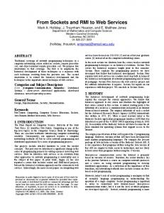
Where host represents the host of the server which creates the group, and rmi://host/Bank is the URL where the first reference of the group is located. Hence, a group creation takes two steps: ?�9;@$46A$BDC < 46.0/FE A < 468�G
?�9;@$46A$BDC < 46.0/FE A < 468�G
�����!#"$�%&�')()��*#+-, < /�8�=>/�8
?�9;@$46A$BDC < 46.0/�132546/-HJI�K < /�8�=>/�8 .0/�132546/-7&8�259;:
�������� �� ����������� �
��������� ���������������������� �
Figure 1: How a group is created. ❶ a server asks the multicast registry for the creation of a new group (Fig. 1.a), then ❷ the new group is registered in the multicast registry as a group composed only of the server originating it (Fig. 1.b). 3.2.5
Look up of a Group Service.
Clients get a representative of the group through a call to the MulticastNaming.lookup method. Through this representative the client accesses to the group services. � public class Client { static Account Group bank; public static void main(String [] args ) { [...] bank = ( Account Group) MulticastNaming.lookup("rmi://"+server+"/Bank"); [...] } �
}
�
7
Walter Cazzola, et al.
Client stub
grop reference
RemoteGroup
...
RemoteObj
RemoteObj
RemoteObj
RemoteObj
... group communication
Figure 2: How a request to a group takes place. The representative, that the client gets, is directly bound to the server that has registered the group. 3.2.6
Requesting a Service Provided by a Group.
Getting a service from a group is carried out through the group representative similarly to a P2P remote invocation. � public class Client { static Account Group bank; public static void main(String[] args) { [...] Integer[] balances = bank.balance(); // } �
asking the state of accounts
}
�
Figure 2 reassembles how the remote method invocation takes place. The stub dispatches the calls using its reference layer. The group reference (layer) forwards the request to the members of the group, collects the results and returns them to the client in form of an array as specified by the group interface. If a failure happens, the behavior depends on the semantic adopted for that multi-point communication (see section 4.1).
8
Walter Cazzola, et al.
� �"!$#&'
� �"!$#&%
�����)*���+=
��� ��