Journal of Computational Mathematics Vol.28, No.4, 2010, 430–460.
http://www.global-sci.org/jcm doi:10.4208/jcm.1003-m0011
SHOCK AND BOUNDARY STRUCTURE FORMATION BY SPECTRAL-LAGRANGIAN METHODS FOR THE INHOMOGENEOUS BOLTZMANN TRANSPORT EQUATION* Irene M. Gamba Department of Mathematics & Institute of Computational Engineering and Sciences, University of Texas Austin
[email protected] Sri Harsha Tharkabhushanam Institute of Computational Engineering and Sciences, University of Texas Austin
[email protected] Abstract The numerical approximation of the Spectral-Lagrangian scheme developed by the authors in [30] for a wide range of homogeneous non-linear Boltzmann type equations is extended to the space inhomogeneous case and several shock problems are benchmark. Recognizing that the Boltzmann equation is an important tool in the analysis of formation of shock and boundary layer structures, we present the computational algorithm in Section 3.3 and perform a numerical study case in shock tube geometries well modeled in for 1D in x times 3D in v in Section 4. The classic Riemann problem is numerically analyzed for Knudsen numbers close to continuum. The shock tube problem of Aoki et al [2], where the wall temperature is suddenly increased or decreased, is also studied. We consider the problem of heat transfer between two parallel plates with diffusive boundary conditions for a range of Knudsen numbers from close to continuum to a highly rarefied state. Finally, the classical infinite shock tube problem that generates a non-moving shock wave is studied. The point worth noting in this example is that the flow in the final case turns from a supersonic flow to a subsonic flow across the shock. Mathematics subject classification: 65T50, 76P05, 76M22, 80A20, 82B30, 82B40, 82B80 Key words: Spectral Numerical Methods, Lagrangian optimization, FFT, Boltzmann Transport Equation, Conservative and non-conservative rarefied gas flows.
1. Introduction A gas flow may be modeled on either a microscopic or a macroscopic level. The macroscopic model regards the gas as a continuum and the description is in terms of variations of the macroscopic velocity, density, pressure and temperature with space and time. On the other hand, the microscopic or molecular model recognizes the particulate structure of a gas as a myriad of discrete molecules and ideally provides information on the position and velocity of every molecule at all times. However, a description in such detail is rarely, if ever, practical and a gas flow is almost invariably described in terms of macroscopic quantities. The two models must therefore be distinguished by the approach through which the description is obtained, rather than by the nature of the description itself. This paper is concerned with the microscopic *
Received January 29, 2009 / Revised version received April 20, 2009 / Accepted June 3, 2009 / Published online April 19, 2010 /
Shock and Boundary Structure Formation for Boltzmann Transport Equation
431
approach and the first question which must be answered is whether this approach can solve problems that could not be solved through the conventional continuum approach. A gas at standard conditions (1 bar, 25o C) contains ca. 2.43 × 10¹⁶ particles per cubic millimeter. Despite this huge number of individual particles, a wide variety of flow and heat transfer problems can be described by a rather low number of partial differential equations, namely the well known equations of Navier-Stokes. Due to the many collisions between particles which effectively distribute disturbances between particles, the particles behave not as individuals, but as a continuum. Under standard conditions, a particle collides with the others very often, about 109 times per second, and travels only very short distances between collisions, about 5 × 10⁻⁸ m. Both numbers, known as collision frequency ν and mean free path l0 , depend on the number density of the gas. The macroscopic quantities at any point in a flow may be identified with average values of appropriate molecular quantities; the averages being taken over the molecules in the vicinity of the point. The continuum description is valid as long as the smallest significant volume in the flow contains a sufficient number of molecules to establish meaningful averages. The existence of a formal link between the macroscopic and microscopic quantities means that the equations which express the conservation of mass, momentum and energy in the flow may be derived from either approach. While this might suggest that neither of the approaches can provide information that is not also accessible to the other, it must be remembered that the conservation equations do not form a determinate set unless the shear stresses and heat flux can be expressed in terms of the other macroscopic quantities. It is the failure to meet this requirement, rather than the breakdown of the continuum description, that places a limit on the range of validity of the continuum equations. More specifically, the Navier-Stokes equations of continuum gas dynamics fail when gradients of the macroscopic variables become so steep that their scale length is of the same order as the average distance traveled by the molecules between collisions, or mean free path, l0 . A less precise but more convenient parameter is obtained if the scale length of the gradients is replaced by the characteristic dimension of the flow, Lf low . Flow problems in which typical length scales Lf low are much larger than the mean free path l0 , or in which the typical frequencies ω are much smaller than ν, are well described through the laws of Navier-Stokes. The Knudsen number Kn = l0 /Lf low is the relevant dimensionless measure to describe these conditions, and the Navier-Stokes equations are valid as long as Kn ¿ 1. This condition fails to hold when the relevant length scale Lf low becomes comparable to the mean free path l0 . This can happen either when the mean free path becomes large, or when the length Lf low becomes small. A typical example of a gas with large mean free path is high altitude flight in the outer atmosphere, where the mean free path must be measured in meters, not nanometers, and the Knudsen number becomes large for, e.g., a spacecraft. Miniaturization, on the other hand, produces smaller and smaller devices, e.g., micro-electro-mechanical systems (MEMS), where the length Lf low approaches the mean free path. Moreover, the Navier-Stokes equations will fail in the description of rapidly changing processes, when the process frequency ω approaches, or exceeds, the collision frequency ν. The Knudsen number (Kn = ω/ν) is used to classify flow regimes as follows: • Kn ¿ 1, i.e., Kn - 0.01: The hydrodynamic regime, which is very well described by the Navier-Stokes equations. • 0.01 - Kn - 0.1: The slip flow regime, where the Navier-Stokes equations can describe the flow well, but must be supplied with boundary conditions that describe velocity slip and temperature jumps at gas-wall interfaces (rarefaction effects).
432
IRENE M. GAMBA AND S.H. THARKABHUSHANAM
• 0.1 - Kn - 10: The transition regime, where the Navier-Stokes equations fail, and the gas must be described in greater detail, e.g., by the Boltzmann equation, or by extended macroscopic models. • Kn & 10: Free molecular flow, where collisions between particles do not play an important role and the flow is dominated by particle-wall interactions. Rarefied gases are gases which are outside the hydrodynamic regime, i.e., Kn & 0.01. For Knudsen numbers 0.01 - Kn - 1, the gas still behaves as a continuum but Navier-Stokes equations fail to describe the underlying physical processes and thus lose their validity and must be replaced by more refined sets of continuum equations that describe the behavior of the gas. There are certain approximation methods to derive equations that allow one to describe these physical processes in rarefied gases and the evaluation of the resulting equations. Most of these methods rely on expansions in the Knudsen number, Kn, and thus yield equations that cannot cover the full transition regime, but are restricted to 0.01 - Kn - 1. A rarefied gas is well described by the Boltzmann equation which describes the statistical state of the gas on the microscopic level accounting for the translation and collisions of the particles. The solution of the Boltzmann equation is the phase probability density distribution f which is a measure for the likelihood to find molecules at a location x with molecular velocities v at a given time t. The Boltzmann equation is the central equation in the kinetic theory of gases. Macroscopic quantities such as mass density ρ, mean velocity (bulk velocity) V, temperature T , pressure tensor p, and heat flux vector q are the weighted averages of the phase density, obtained by integration over the molecular velocity. One way to compute the macroscopic quantities is to use rational methods to deduce macroscopic transport equations from the Boltzmann equation, that is to get transport equations for the macroscopic quantities ρ, V, T , etc. This is suitable for processes at small and moderate Knudsen numbers, which as it turns out, can be described by a small number of equations. Alternatively, the Boltzmann equation can be solved and its solution f integrated over the molecular velocity, v, domain. Such an approach is not restricted by the range of the Knudsen number values and can be used in analysis of systems where Kn & 0.01 (rarefied gases). The work in this paper concentrates on solving the Boltzmann equation for rarefied gases and subsequent analysis of 3D in v (space homogenous) and 1D in x and 3D in v (space inhomogeneous) systems. In addition to the description based on the Boltzmann equation, the study of rarefied flows requires an additional piece of information concerning the interaction of gas molecules with the solid (or, possibly liquid) surfaces that bound the gas expanse. It is to this interaction that one can trace the origin of the drag and lift exerted by the gas on the body and the heat transfer between the gas and the solid boundary. The study of gas-surface interaction may be regarded as a bridge between the kinetic theory of gases and solid state physics. The difficulties of a theoretical investigation are due mainly to our lack of knowledge of the structure of surface layers of solid bodies and hence of the effective interaction potential of the gas molecules with the wall. When a molecule impinges upon a surface, it is absorbed and may form chemical bonds, dissociate, become ionized, or displace surface molecules. Its interaction with the solid surface depends on the surface finish, the cleanliness of the surface, its temperature, etc. It may also vary with time because of outgassing from the surface. Preliminary heating of a surface also promotes purification of the surface through emission of adsorbed molecules. In general, adsorbed layers may be present; in this case, the interaction of a given molecule with the surface may also depend on the distribution of
Shock and Boundary Structure Formation for Boltzmann Transport Equation
433
molecules impinging on a surface element. This physical aspect has a mathematical counterpart: The Boltzmann equation must be accompanied by boundary conditions, which describe the aforementioned interaction of the gas molecules with the solid walls. Rarefied gas analysis using the Boltzmann equation has a vast number of applicable areas. In the area of environmental problems, understanding and controlling the formation, motion, reactions, and evolution of particles of varying composition and shapes, as well as their spacetime distribution under gradients of concentration, pressure, temperature, and the action of radiation, has grown in importance. This is because of the increasing awareness of the local and global problems related to the emission of particles from electric power plants, chemical plants, and vehicles as well as of the role of small particles in fog and cloud formation, radioactive releases, etc. Another area of application of rarefied gas dynamics is in the design of micro machines whose sizes range from a few microns to a few millimeters. Rarefied flows can form the basis of design of important micromechanical systems. In this paper, the areas of formation, propagation and analysis of shocks and some some classical hydrodynamic examples have been studied. From the computational point of view, one of the well-known and well-studied methods developed in order to solve the Boltzmann equation is a stochastic based method called “Direct Simulation Monte-Carlo” (DSMC) developed initially by Bird [4] and Nanbu [42] and more recently by [47,48]. This method is usually employed as an alternative to hydrodynamic solvers to model the evolution of moments or hydrodynamic quantities. In particular, this method have been shown to converge to the solution of the classical Boltzmann equation in the case of monatomic rarefied gases [52]. One of the main drawbacks of such methods is the inherent statistical fluctuations in the numerical results, which becomes very expensive or unreliable in the presence of non-stationary flows or non equilibrium statistical states, where more information is desired about the evolving probability distribution. Currently, there is extensive work from Rjasanow and Wagner [48] and references therein, to determine accurately the high-velocity tail behavior of the distribution functions from DSMC data. Implementations for micro irreversible interactions such as inelastic collisions have been carefully studied in [29]. In contrast, a deterministic method computes approximations of the probability distribution function using the Boltzmann equation, as well as approximations to the observables like density, momentum, energy, etc. There are currently two deterministic approaches to the computations of non-linear Boltzmann, one is the well known discrete velocity models and the second a spectral based method, both implemented for simulations of elastic interactions, i.e., energy conservative evolution. Discrete velocity models were developed by Broadwell [16] and mathematically studied by Cabannes, Illner and Kawashima among many authors [17, 35, 36]. More recently these models have been studied for many other applications on kinetic elastic theory in [7, 21, 33, 39, 54]. These models have not adapted to inelastic collisional problems up to this point according to our best knowledge. Spectral based models, which are the ones of our choice in the current work where already implemented by the authors in the space homogeneous setting for conservative or dissipative interactions [30]. These methods, which have been originally developed by Pareschi, Gabetta and Toscani [26], and later by Bobylev and Rjasanow [13] and Pareschi and Russo [46], are supported by the ground breaking work of Bobylev [5] using the Fourier Transformed Boltzmann Equation to analyze its solutions in the case of Maxwell type of interactions. After the introduction of the inelastic Boltzmann equation for Maxwell type interactions and the use of the Fourier transform for its analysis by Bobylev, Carrillo and Gamba [6], and more general complex dissipative
434
IRENE M. GAMBA AND S.H. THARKABHUSHANAM
flow models [8, 9], the spectral based approach is becoming the most suitable tool to deal with deterministic computations of kinetic models associated with the Boltzmann non-linear binary collisional integral, both for elastic or inelastic interactions. More recent implementations of spectral methods for the non-linear Boltzmann equation are due to Bobylev and Rjasanow [15], who developed a method using the Fast Fourier Transform (FFT) for Maxwell type interactions, and then for Hard-Sphere interactions [14] using generalized Radon and X-ray transforms via FFT. Simultaneously, L. Pareschi and B. Perthame [45] developed a similar scheme using FFT for Maxwell type interactions. Later, I. Ibragimov and S. Rjasanow [34] developed a numerical method to solve the space homogeneous Boltzmann Equation on a uniform grid for variable hard potential (VHP) interactions with elastic collisions. Our current spectral scheme [30] incorporates Lagrange multipliers to enforce conservation properties and it works both in the for inelastic or elastic interactions for both Maxwell type or variable hard spheres interactions as those analyzed in [1, 10, 11, 27, 28, 43] were rigorous arguments for the formation of nonequilibrium statistical states are found. These analytical and qualitative results not only have inspired us in the design of the computational algorithm and scheme, but also are serving us in the analysis of the spectral accuracy and approximation properties of the space inhomogeneous scheme [31]. We mention that, most recently, Filbet and Russo [23, 24] implemented a method to solve the space inhomogeneous Boltzmann equation using the previously developed spectral methods in [45,46]. The afore mentioned work in developing deterministic solvers for the non-linear BTE have been restricted to elastic, conservative interactions. Finally, Mouhot and Pareschi [41] have studied the approximation properties of the schemes. Part of the difficulties in their strategy arises from the constraint that the numerical solution has to satisfy conservation of the initial mass. To this end, the authors propose the use of a periodic representation of the distribution function to avoid aliasing. There is no conservation of momentum and energy in any of the solvers proposed in [23, 24, 41] and in all cases, which are developed in 2 and 3 velocity dimensions, do not guarantee the positivity of the solution due to the fact that the truncation of the velocity domain combined with the Fourier method makes the distribution function negative at times. The lack of positivity is a shortcoming of the spectral approach remains in our proposed technique, however we are able to handle conservation in a very natural way by means of Lagrange multipliers [30]. Our proposed approach is different and it takes a smaller number of operations to compute the collision integral. In the case of the space inhomogeneous problems presented here, our interest lies in shock tube test problems and in the the approximation of shock waves or shock layers. In the Euler set of equations in classical fluid dynamics, the shock layer is treated as a discontinuity. Its internal structure is discussed using the Navier-Stokes equations. However, the thickness of such a shock layer is of the order of mean free path and thus the Navier-Stokes equations are invalid for such an analysis. For this purpose, the Boltzmann equation is used. Consider a time-independent unidirectional flow in an infinite expanse of a gas, where the states at infinities are both uniform. The states at infinities being uniform, the velocity distribution functions are Maxwellian with corresponding densities, flow velocities and pressures. Such a choice of averages cannot be made arbitrarily and are derived from the Rankine-Hugoniot relations. Obviously, when the two states at infinities are equal, the uniform state is a solution. The mathematical theory of the existence of a nontrivial solution is studied by Caflisch and Nicolaenko [19] and Liu and Yu [38], and the existence and uniqueness of a weak shock wave
Shock and Boundary Structure Formation for Boltzmann Transport Equation
435
solution, where the two uniform states at infinities are very close, is proved. Such a profile has been described by Grad [32] and is given by a slowly varying local Maxwellian with the parametric averages given from the fluid dynamic equations. Liu and Yu [38] also prove that the distribution function is positive in the shock layer and that the solution is stable. Other numerical analysis of shock structures include the pioneering work of Mott and Smith in [40], Liepmann, Narasimha and Chahine [37], Salwen, Grosch and Ziering [49], Ohwada [44], Cercignani, Frezzotti and Grosfils [22], Takata, Aoki and Cercignani [51]. Many of the above are discussions of numerical approximations of the shock wave rather than their physical nature. Takata, Aoki and Cercignani [51] carried out the analysis on the basis of Grad [32] and Caflisch [18] for a hard-sphere gas, according to which the trace of the singular character at upstream infinity remains at downstream infinity. Yu [53] used Hilbert expansions to study the behavior of a gas when the length and time scales of variations are much larger than the mean free path and mean free time respectively and extended the expansion to include a discontinuity caused by the shock wave in the solution. The above analysis was done for a one space dimensional case where it was also proven that the obtained solution approximates the Boltzmann solution for weak shocks. It is expected that in a one dimensional problem, where the two equilibrium states are in contact with each other initially, the Euler equations dictate the propagation of the initial shock discontinuity where no expansion wave appears. Then, the time evolution of the Boltzmann equation reveals the formation of a shock layer through the initial layer and its propagation, which supplements the work of Yu [53].
2. The Space Inhomogeneous Boltzmann Transport Equation The Boltzmann Transport Equation describes the statistical (kinetic) evolution of a single point probability distribution function f (x, v, t) for x ∈ Ωx ⊂ Rd , v ∈ Rd (where d is the velocity space dimension). The probability distribution function f (x, v, t) describes the probability of finding a particle at x with velocity v at time t. For variable hard potential interactions, the corresponding initial value-boundary value problem in the presence of a force field F with a post-collisional specular reflection direction σ, is given by ∂ f (x, v, t) + v · 5x f (x, v, t) + 5v · (Ff (x, v, t)) = Q(f, f ) , ∂t
(2.1)
with f (x, v, 0) = f0 (x, v) , f (x, v, t) = fB (x, v, t) ∀
x ∈ ∂Ωx ,
where the initial probability distribution f0 (x, v) is assumed to be integrable and the boundary condition fB (x, v, t) ∀ x ∈ ∂Ωx is given in Section 2.2. The collision or interaction operator Q(f, f ) is a bi-linear integral form that can be defined in weak or strong form. The classical Boltzmann formulation is given in strong form is classically given in three space dimensions for hard spheres by µ ¶ Z 1 0 0 Q(f, f ) = f (x, v, t)f (x, w, t) − f (x, v, t)f (x, w, t) |u · η| dηdw, (2.2) 0e 0J w∈Rd ,η∈S d−1 where the integration over the sphere is done with respect to η, the direction that contains the two centers at the time of the interaction, also referred as the impact direction. We denote by
436
IRENE M. GAMBA AND S.H. THARKABHUSHANAM
0
v and 0w the pre-collisional velocities corresponding to v and w. In the case of micro-reversible (elastic) collisions one can replace 0v and 0w with v0 and w0 respectively in the integral part of (2.2). The exchange of velocities law is given by u=v−w 1+e v0 = v − (u · η)η, 2
relative velocity 1+e w0 = w + (u · η)η . 2
(2.3)
This collisional law is equivalent to u0 · η = −eu · η and u0 ∧ η = u ∧ η. The parameter e = e(|u · η|) ∈ [0, 1] is the restitution coefficient covering the range from sticky to elastic interactions, so 0e = e(|0u · η|), with 0u the pre-collisional relative velocity. The 0 ,w0 ) Jacobian J = | ∂(v ∂(v,w) | of post-collisional velocities with respect to pre-collisional velocities 0
0
v, w) depends also on the local energy dissipation [20]. In particular, 0J = | ∂( ∂(v,w) |. In addition, it can be seen in general that it is a function of the quotient of relative velocities and the restitution coefficient as well. For example and in the particular case of hard spheres interactions
J(e(z)) = e(z) + z e(z) = (z e(z))z
with z = |u · η| .
When e = 1 then the collision law is equivalent to specular reflection with respect to the plane containing η, orthogonal to the corresponding tangent plane to the sphere of influence. The direction η is also called the impact direction. We note that J = 1 when e = 1, that is, for elastic hard sphere interactions. The corresponding weak formulation of the collisional form becomes more transparent and crucial in order to write the inelastic equation in higher dimensions or for more general collision kernels. Such formulation, originally due to Maxwell for the space homogeneous form is often called the Maxwell form of the Boltzmann equation. The integration is parametrized in terms of the center of mass and relative velocity. And on the d − 1 dimensional sphere, integration is done with respect to the unit direction σ given by the elastic post collisional relative velocity, that is Z Q(f, f ) φ(v) dv Zv∈R
d
f (x, v, t)f (x, w, t)[φ(v0 ) − φ(v)] B(|u|, µ) dσdwdv,
=
(2.4)
v, w ∈ R2d , σ ∈ S d−1
where the corresponding velocity interaction law is now given by β (|u|σ − u), 2 u0 = (1 − β)u + β|u|σ u·σ µ = cos(θ) = |u| v0 = v +
B(|u|, µ) = |u|λ b(cos θ) Z π ωd−2 b(cos θ) sind−2 θdθ < K
β (|u|σ − u) , 2 (inelastic relative velocity) , w0 = w −
(cosine of the elastic scattering angle) , with 0 ≤ λ ≤ 1 ,
(2.5)
(Grad cut-off assumption) ,
0
β=
1+e 2
(energy dissipation parameter) .
We denote by 0v and 0w the pre-collision velocities corresponding to v and w. In the case of micro-reversible (elastic) collisions one can replace 0v and 0w with v0 and w0 respectively in the
Shock and Boundary Structure Formation for Boltzmann Transport Equation
437
integral part of (2.1). We assume the differential cross section function b(u · σ/|u|) is integrable with respect to the post-collisional specular reflection direction σ in the d − 1 dimensional sphere, referred as the Grad cut-off assumption, and that b(cos θ) is renormalized such that µ
Z b S d−1
u·σ |u|
Z
π
b(cos θ) sind−2 θ dθ
dσ = ωd−2 Z
0 1
b(µ)(1 − µ2 )(d−3)/2 dµ = 1 ,
=ωd−2
(2.6)
−1
where the constant ωd−2 is the measure of the d − 2 dimensional sphere and the corresponding scattering angle is θ is defined by cos θ = σ · u/|u|. The above equation 2.6 is written for a general d. The parameter λ regulates the collision frequency as a function of the relative speed |u|. It accounts for inter particle potentials defining the collisional kernel and they are referred to as Variable Hard Potentials (VHP) whenever 0 < λ < 1, Maxwell Molecules type interactions (MM) for λ = 0 and Hard Spheres (HS) for λ = 1. The Variable Hard Potential collision kernel then takes the following general form: B(|u|, µ) = Cλ (σ)|u|λ ,
(2.7)
with Cλ (σ) = b(θ)/4π, λ = 0 for Maxwell type of interactions; Cλ (σ) = a2 /4, λ = 1 for Hard Spheres (with a = particle diameter). For 3-D in v, Cλ (σ) = 1/4π. In addition, if Cλ (σ) is independent of the scattering angle we call the interactions isotropic. Otherwise we refer to them as anisotropic Variable Hard Potential interactions. Depending on their nature, collisions either conserve density, momentum and energy (elastic) or density and momentum (inelastic) or density (elastic - linear Boltzmann operator), depending on the number of collision invariants the operator Q(f, f ) has. In the case of the classical Boltzmann equation for rarefied (elastic) monatomic gases, the collision invariants are exactly d + 2, that is, according to the Boltzmann theorem, the number of polynomials in velocity space v that generate φ(v) = A + B · v + C|v|2 , with C ≤ 0. In particular, one obtains the following classical conserved quantities written in d = 3 dimensions: Z f (x, v, t)dv , Density ρ(x, t) = v∈Rd
Flow velocity vector Temperature Pressure Specific internal energy Stress tensor, Heat-flow vector
V(x, t) =
1 ρ(x, t)
Z vf (x, v, t)dv , v∈Rd
Z 1 3RT (x, t) = |v − V|2 f (x, v, t)dv , ρ(x, t) v∈Rd Z 1 |v − V|2 f (x, v, t)dv = Rρ(x, t)T , p(x, t) = (2.8) 3 v∈Rd Z 1 3 e(x, t) = |v − V|2 f (x, v, t)dv = RT , 2ρ(x, t) v∈Rd 2 Z p(x, t) = {pij }(x, t) pij = (vi − Vi )(vj − Vj )f (x, v, t)dv , q(x, t) =
1 2
Z
v∈Rd
(v − V)|v − V|2 f (x, v, t)dv , v∈Rd
438
IRENE M. GAMBA AND S.H. THARKABHUSHANAM
where R is the specific gas constant. Of significant interest from the statistical view point are the evolution of moments or observables, at all orders. They are defined by the dynamics of the corresponding time evolution equation for the velocity averages, given by Z Z ∂ ∨j ∨j Mj (x, t) = f (x, v, t)v° dv = Q(f, f )v° dv , (2.9) ∂t v∈Rd v∈Rd ∨j where, v° = the standard symmetric tensor product of v with itself, j times. Thus, according to (2.8), for the classical elastic Boltzmann equation, the first d + 2 moments are conserved, meaning, Z ∨j f0 (x, v)v° dv for j = 0, 1;
Mj (x, t) = M0,j = v∈Rd
and
Z f0 (x, v)|v|2 dv.
E(x, t) = tr(M2 )(x, t) = E0 = v∈Rd
Other higher order moments of interest and alternate moment forms are Z M omentumF low M2 (x, t) = vvT f (x, v, t)dv
(2.10a)
Rd
Specif icinternalEnergy
E(x, t) =
µ ¶ 1 tr(M2 (x, t)) − ρ(x, t)|V(x, t)|2 , 2ρ(t)
(2.10b)
with k− Boltzmann constant. 2.1. Spectral method Let v = (v1 , v2 , . . . , vd ) be the velocity space variable and ζ = (ζ 1 , ζ 2 , . . . , ζ d ) be the Fourier space variable. One of the pivotal points in the derivation of the spectral numerical method, developed by the authors in [30] for the computation of the non-linear Boltzmann equation lies in the representation of the collision integral in Fourier space by means of its weak form. For ease of notation, the time and space dependence in f are ignored in the rest of this chapter. Then for a suitably regular test function ψ(v), the weak form of the collision integral is given by µ ¶ Z Z Q(f, f )ψ(v)dv = f (v)f (w)B(|u|, µ) ψ(v0 ) − ψ(v) dσdwdv , (2.11) v∈Rd
(w, v) ∈ Rd × Rd , σ ∈ S d−1
where v0 , w0 , u, B(|u|, µ) are given by (2.5). In particular, √ ψ(v) = e−iζ·v /( 2π)d , where ζ is the Fourier variable, we get the Fourier Transform of the collision integral through its weak form Z 1 b √ Q(ζ) = Q(f, f )e−iζ·v dv ( 2π)d v∈Rd µ ¶ Z B(|u|, µ) −iζ·v0 = f (v)f (w) √ e − e−iζ·v dσdwdv . (2.12) ( 2π)d (w,v)∈Rd ×Rd , σ∈S d−1
439
Shock and Boundary Structure Formation for Boltzmann Transport Equation
b = F(.) to denote the Fourier transform and F −1 for the classical inverse Fourier We will use [.] transform. Plugging in the definitions of collision kernel B(|u|, µ) = Cλ (σ)|u|λ (which in the case of isotropic collisions would just be the Variable Hard Potential collision kernel) and the post collisional velocity, v0 from (2.5), we get 1 b Q(ζ) = √ ( 2π)d
Z (w, v) ∈ Rd × Rd , σ ∈ S d−1
µ ¶ β f (v)f (w)Cλ (σ)|u|λ e−iζ·v e−i 2 ζ·(|u|σ−u)−1 dσdwdv . (2.13)
From u = v − w, we have w = v − u ⇒ dw = du [Jacobian of this change of variable matrix is 1]. This gives Z b Q(ζ) =
β
(w, v) ∈ Rd × Rd , σ ∈ S d−1
f (v)f (v − u)Cλ (σ)|u|λ e−iζ·v [e−i 2 ζ·(|u|σ−u)) − 1]dσdudv.
(2.14)
Upon further simplification, (2.14) can be rewritten as Z Z 1 b Q(ζ) = √ Gλ,β (u, ζ) f (v)f (v − u)e−iζ·v dvdu d ( 2π)d u∈Rd v∈R Z = Gλ,β (u, ζ)F[f (v)f (v − u)]du ,
(2.15)
u∈Rd
where Z β
Cλ (σ)|u|λ [e−i 2 ζ·(|u|σ−u)) − 1]dσ
Gλ,β (u, ζ) = σ∈S d−1
"
=|u|
λ
e
iβ 2 ζ·u
#
Z (Cλ (σ)e
−i β 2 |u|ζ·σ
− 1)dσ .
(2.16)
σ∈S d−1
Note that (2.16) is valid for both isotropic and anisotropic interactions. For the former type, a simplification ensues due to the fact the Cλ (σ) is independent of σ ∈ S d−1 : · ¸ β β|u||ζ| Gλ,β (u, ζ) = Cλ ωd−1 |u|λ ei 2 ζ.u sinc( )−1 . 2
(2.17)
Thus, it is seen that the integration over σ on the unit sphere S d−1 is completely independent, and there is actually a closed form expression for this integration, given by (2.17) in the case of isotropic collisions. In the case of anisotropic collisions, the dependence of Cλ on σ is again isolated into a separate integral over the unit sphere S di− as given in (2.16). The above expression can be transformed for elastic collisions β = 1 into a form suggested by Rjasanow and Ibragimov in d = 3 [34]. Further simplification of (2.15) is possible by observing that the Fourier transform inside the integral can be written in terms of the Fourier transform of f (v) since it can also be written
440
IRENE M. GAMBA AND S.H. THARKABHUSHANAM
as a convolution of the Fourier transforms. Let fu (v) = f (v − u) Z b Q(ζ) = Gλ,β (u, ζ)F(f fu )(ζ)du d
Zu∈R
1 (fˆ ∗ fc Gλ,β (u, ζ) √ u )(ζ)du ( 2π)d Z Z 1 = Gλ,β (u, ζ) √ fˆ(ζ − ξ)fc u (ξ)dξdu ( 2π)d ξ∈Rd u∈Rd Z Z 1 fˆ(ζ − ξ)fˆ(ξ)e−iξ·u dξdu = Gλ,β (u, ζ) √ d d ( 2π) ξ∈R u∈Rd Z 1 ˆ λ,β (ξ, ζ)dξ, = √ fˆ(ζ − ξ)fˆ(ξ)G ( 2π)d ξ∈Rd =
u∈Rd
where
(2.18)
Z ˆ λ,β (ξ, ζ) = G
u∈Rd
Gλ,β (u, ζ)e−iξ·u du.
b In particular, Q(ζ) is a weighted convolution in Fourier space. Let u = re, e ∈ S d−1 , r ∈ R. For example in d = 3, follows the convolution weight in Fourier space can be written as Z Z ˆ λ,β (ξ, ζ) = G r2 G(re, ζ)e−irξ·e dedr (2.19) r e · µ ¶ µ ¶ ¸ Z rβ|ζ| β =16π 2 Cλ rλ+2 sinc sinc r|ξ − ζ| − sinc(r|ξ|) dr . 2 2 r 3 3 Since √ the domain of computation is restricted to Ωv = [−L, L) , u ∈ [−2L, 2L) then r ∈ [0, 2 3L], and the right hand side of (2.19) is the finite integral
Z 2
16π Cλ 0
√ 2 3L
· µ ¶ µ ¶ ¸ rβ|ζ| β rλ+2 sinc sinc r|ξ − ζ| − sinc(r|ξ|) dr. 2 2
(2.20)
A point worth noting here is that the above formulation (2.18) results in O(N 2d ) number of operations, where N is the number of discretizations in each velocity direction. Also, exploiting the symmetric nature in particular cases of the collision kernel one can reduce the number of operations to O(N d log N ) in velocity space (or N log N if N counts the total number of Fourier nodes in d dimensional velocity space). 2.2. Kinetic Boundary Conditions: Simple Boundary On a boundary or a wall where there is no mass flux across it, which will be called a simple boundary, the following condition called the Maxwell-type condition is widely used (for d = 3): f (x, v, t) =(1 − α)f (x, v − 2[(v − Vw ) · n]n, t) ¶ µ ασw |v − Vw |2 + [(v − Vw ) · n > 0] , exp − 2RTw (2πRTw )3/2 ¶1/2 Z µ 2π [(v − Vw ) · n]f (x, v, t)dv , σw = − RTw [(v−Vw )·n 0] . (2.22) (v∗ −Vw )·n 0, (v∗ − Vw ) · n < 0], Z (v − Vw ) · n KB (v, v∗ )dv = 1 [(v − Vw ) · n > 0, (v∗ − Vw ) · n < 0], • − (v ∗ − Vw ) · n [(v−Vw )·n>0] which corresponds to the condition of a simple boundary. • When the kernel KB is determined by the local condition of the boundary, Z KB (v, v∗ )fB (v∗ )dv∗ [(v − Vw ) · n > 0] , fB (v) =
(2.23)
[(v∗ −Vw )·n 0], exp − + [(ˆ v−V 3/2 ˆ ˆ (π Tw ) Tw µ ¶1/2 Z π ˆ w ) · n]ˆ σ ˆw = −2 [(ˆ v−V f (ˆ x, v ˆ, ˆ t)dˆ v. Tˆw ˆ
(2.31)
(ˆ v−Vw )·n 0 be the integration weights for j = 1, 2, ..., M . Let ¡ ¢ ˜ = Q ˜1 Q ˜2 . . Q ˜M T Q be the distribution vector at the computed time step and Q=
¡
Q1
Q2
. .
QM
¢T
444
IRENE M. GAMBA AND S.H. THARKABHUSHANAM
be the corrected distribution vector with the required moments conserved. For the elastic case, let ωj e Cd+2×M = vi ωj 2 |v| ωj and correspondingly, let aed+2×1 =
¡
ρ m1
...
md
e
¢T
be the vector of conserved quantities. Using the above vectors, the conservation method can be written as a constrained optimization problem: Find Q s.t. n o ˜ − Qk2 : Ce Q = ae ; Ce ∈ Rd+2×M , Q ˜ ∈ RM , ae ∈ Rd (∗) minkQ 2 To solve (*), one can employ the Lagrange multiplier method. Let γ ∈ Rd be the Lagrange multiplier vector. Then the scalar objective function to be optimized is given by L(Q, λ) =
M X
˜ j − Qj |2 + γ T (Ce Q − ae ) . |Q
(2.32)
j=1
Eq. (2.32) can be solved explicitly for the corrected distribution value and the resulting equation of correction be implemented numerically in the code. Taking the derivative of L(Q, λ) with respect to fj , j = 1, ..., M , and γi , i = 1, ..., d + 2, i.e., gradients of L, ∂L = 0, ∂Qj
j = 1, ..., M ,
˜ + 1 (Ce )T γ . ⇒Q=Q 2
(2.33)
Moreover, ∂L = 0; i = 1, ..., d + 2 , ∂γ1 ⇒ Ce Q = ae ,
(2.34)
retrieves the constraints. Solving for γ, ˜ . Ce (Ce )T γ = 2(ae − Ce Q)
(2.35)
Now Ce (Ce )T is symmetric and, because Ce is the integration matrix, Ce (Ce )T is positive definite. By linear algebra, the inverse of Ce (Ce )T exists. In particular, one can compute the value of λ by ˜ . γ = 2(Ce (Ce )T )−1 (ae − Ce Q) Substituting γ into (2.33), since ae = 0, ˜ + (Ce )T (Ce (Ce )T )−1 (ae − Ce Q) ˜ Q =Q £ ¤ ˜ = I − (Ce )T (Ce (Ce )T )−1 Ce Q ˜, =ΛN (Ce )Q
(2.36)
Shock and Boundary Structure Formation for Boltzmann Transport Equation
445
where I = N × N identity matrix and we define ΛN (Ce ) : I − (Ce )T (Ce (Ce )T )−1 Ce . For the future sections, define this conservation routine as Conserve. So, ˜ = Q = ΛN (Ce )Q ˜. Conserve(Q) Define Dt f to be any order time discretization of
∂f ∂t .
(2.37)
Then we have:
˜, Dt f = ΛN (Ce )Q
(2.38)
where we expect the required observables are conserved and the solution approaches a stationary state for the elastic space homogeneous Boltzmann equation, since lim kΛN (C) Q(fjn , fjn )k∞ = 0
n→∞
see [30]. Identity (2.38) summarizes the whole conservation process. As described previously, setting the conservation properties as constraints to a Lagrange multiplier optimization problem ensures that the required observables are conserved.
3. Properties of the Boltzmann Transport Equation and Spectral Method 3.1. Velocity and Fourier Space Discretization Due to the nature of the presented numerical application, we restrict the notation to the d = 3-dimensional case. The distribution function is generally not compactly supported in v but is usually negligible outside of a small ball © ª BLx (V) = v ∈ R3 : |v − Vx | ≤ Lx , where VX is the flow velocity and depends on the space variable x. As mentioned in the description of the spectral method, we restrict to distribution functions that are compactly supported, i.e., suppf (x, ., t) = BLx (Vx ), ∀x ∈ Ωx , t ≥ 0 . Consider the cube © CLx (Vx ) = v ∈ R3 : |vj − Vx,j | ≤ Lx ,
ª j = 1, 2, 3 .
It is easy to see that BLx (Vx ) ⊂ CLx (Vx ), and such a discretization is used for all velocity variables v, v∗ . For the rest of the paper, the cube is considered as the domain of computation instead of a ball as it is numerically easier to implement. This yields the following discretization space for the relative velocity u = v − v∗ u ∈ C2Lx (0) . Let N ∈ N be a natural number. Then we denote by CN the following three-dimensional indices CN = {k = (k1 , k2 , k3 ) ∈ Z3 : 0 ≤ km < N,
m = 1, 2, 3} .
Introducing the velocity mesh size hv = 2Lx /N , we get the following discrete velocities ¾ ½ N Cv = vj = Vx + (hv − )j, j ∈ CN ⊂ CLx (VX ) . 2
446
IRENE M. GAMBA AND S.H. THARKABHUSHANAM
Similarly, the appropriate set for the relative velocity u is ¾
½ Cu =
N vj = (hv − )j, 2
j ∈ CN
⊂ C2Lx (0) .
Because, an FFT package is used [25], the discrete velocity space then requires the Fourier space mesh size hζ = 2Lζ /N to be given from hv as hv hζ =
2π , N
i.e.,
hζ =
π , Lx
and the discrete Fourier variable set is given by Cζ = {ζ = hζ j,
j ∈ CN } .
3.2. Balance Equations In the elastic collision case, multiplying the Boltzmann equation (2.1) by 1, v, |v|2 and integrating the result over the whole space of v, we obtain the following balance (conservation) hydrodynamic equations: ∂ρ + 5x · (ρV) = 0, ∂t d X ∂ ∂ (ρVi ) + (ρVi Vj + pij ) = ρFi ∂t ∂x j j=1
(3.1a) ∀i = 1, 2, 3,
(3.1b)
· µ ¶¸ X · µ ¶ ¸ d ∂ 1 ∂ 1 2 2 ρ e + |V| + ρVj e + |V| + V · pj + qj = ρV · F , (3.1c) ∂t 2 ∂xj 2 j=1 where F is assumed to be independent of molecular velocities v. The collision term vanishes on integration in the velocity domain. Eqs. (3.1) are referred to as the balance (conservation) equations of mass, momentum and energy respectively. In classical fluid dynamics in statistical equilibrium, pij and qi are assumed to be in appropriate forms to close the system (3.1c). For example, pij = pδij ,
qi = 0 ,
(3.2)
or à pij = pδij − µ
d
∂Vj 2 X ∂Vk ∂Vi + − δij ∂xj ∂xi 3 ∂xk k=1
qi = −λ
∂T , ∂xi
! − µB
d X ∂Vk k=1
∂xk
δij ,
(3.3a) (3.3b)
where δij is Kronecker’s delta and µ, µB and λ, called the viscosity, bulk viscosity, and thermal conductivity of the gas respectively, are functions of temperature. The set of equations with the former stress and heat flow is called the Euler equations (3.2), and the set with the latter the Navier-Stokes equations (3.3b). The relations for pij and qi given in (3.3b) are called the Newton’s law and Fourier’s law, respectively.
Shock and Boundary Structure Formation for Boltzmann Transport Equation
447
3.3. Collision Integral Algorithm ¯ λ,β (ξ, ζ) from (2.20) can be computed The collision integral is given by (2.18) and (2.20). G either in advance and stored or at run time. Depending on the computing strategy employed, a operation efficient (former) or a memory efficient (latter) approach can be implemented. ¯ l,m := G ¯ λ,β (ξl , ζm ) for a particular choice of λ and β. Then the process of computing Define G the collision integral can be summarized into the following algorithm, wherein ω[l] are the integration weights. For the purpose of numerical analysis in the rest of the chapter, trapezoidal rule weights are used. Algorithm [1] (O(N 3 log(N )))fˆ(ζm ) = FFTvk →ζm [f (vk )] [2] (O(N 3 )) [2.1]
For ζm ∈ Cu ,
Do
ˆ m) = 0 Q(ζ
[2.2] (O(N 3 ))
For ξl ∈ Cu , Do [2.2.1] g(ξl ) = fˆ(ξl ) × fˆ(ζm − ξl ) ˆ m ) = Q(ζ ˆ m) + G ¯ l,m × ω[l] × g(ξl ) [2.2.2] Q(ζ
[2.2]* [2]*
End Do End Do
ˆ m )] [3] (O(N log(N )))Q(vk ) = IFFTζm →vk [Q(ζ 3
3.4. Temporal and Advection Approximation After the discretization of the collision integral, the problem of numerically solving the ∂ Boltzmann equation reduces to approximating the time derivative ∂t and the advection term v · 5x f (x, v, t) + 5v · (Ff (x, v, t)) in (2.1). The current section describes a standard way of dealing with the advection term in the space inhomogeneous Boltzmann equation. A description of the time and space discretizations which are employed is also given.
3.4.1. Time Splitting When computing the space inhomogeneous Boltzmann transport equation with zero force field, i.e., F = (0, 0, 0), a reliable way of devising a numerical approximation is to employ an efficient time-splitting method. The problem of solving equation (2.1) with F = (0, 0, 0) is divided into two smaller subproblems. We discretize time into discrete values tn = t0 + n ∗ dt, where dt > 0 is the time step size. Denote f (x, v, tn ) by fn (x, v). Using a first order time-splitting scheme, in a small time interval [tn , tn+1 ], the two subproblems are given by • The Advection (Collisionless) Problem ∂ g(x, v, t) + v · 5x g(x, v, t) = 0, ∂t g(x, v, 0) = fn (x, v).
(3.4a) (3.4b)
448
IRENE M. GAMBA AND S.H. THARKABHUSHANAM
• The Homogenous (Collision) Problem ∂ ˜ f (x, v, t) = Q(f˜, f˜), ∂t f˜(x, v, 0) = g(x, v, dt).
(3.5a) (3.5b)
Let A(dt) and H(dt) be solution operators corresponding to (3.4b) and (3.5b), respectively. Then the solutions for (3.4b) and (3.5b) can be rewritten as g(x, v, dt) = A(dt)fn (x, v), f˜(x, v, dt) = H(dt)g(x, v, dt),
(3.6a) (3.6b)
and the computed solution at time step tn+1 is given by fn+1 (x, v) = f (x, v, tn+1 ) = H(dt)A(dt)fn (x, v) .
(3.7)
This is a time-splitting method that is first order in time. Eq. (3.7) is usually good enough for kinetic problems. Nevertheless, for non-stiff problems a second order time-splitting method (Strang splitting) can be employed: fn+1 (x, v) = f (x, v, tn+1 ) = A(dt/2)H(dt)A(dt/2)fn (x, v) .
(3.8)
Using Strang splitting to separate the advection and homogenous calculations, the overall finite difference scheme is second order in time provided that a second order in time scheme is used in each of the subproblems. When lower order schemes are used for 3.4b and 3.5b a lower order time splitting scheme suffices. Whenever a higher order schemes are used for 3.4b and 3.5b, the use of a higher order time splitting scheme (e.g., Strang splitting scheme) becomes imperative. 3.4.2. Space Discretization We now turn to finite differences schemes for the advection operator. This is the first step in time splitting procedure mentioned above, i.e., collisionless step. For simplicity, only 1D flows in x direction are considered. So (3.4b) reduces to ∂ ∂ g(x, v, t) + v1 g(x, v, t) = 0 , ∂t ∂x where v = (v1 , v2 , v3 ) is used. A first order scheme that is used is the standard upwind scheme. Let xj = x0 + jdx and gnj (v) = g(xj , v, tn ). Then j gn+1 (v) − gnj (v) g j (v) − gnj−1 (v) + v1 n = 0, v1 ≥ 0 (3.9a) dt dx j gn+1 (v) − gnj (v) g j+1 (v) − gnj (v) + v1 n = 0, v1 < 0, (3.9b) dt dx gives the upwind scheme for appropriate signs of v1 . As is the case with explicit finite difference schemes, (3.9b) is restricted by the CFL condition which guarantees that the numerical domain of dependence includes the analytical domain of dependence. For (3.9b), the CFL condition is dt given by |max(v1 ) dx | ≤ 1. When necessary, the following second order upwind scheme is used: j gn+1 (v) − gnj (v) g j−2 (v) − 4gnj−1 (v) + 3gnj (v) + v1 n = 0, v1 ≥ 0 dt 2dx j gn+1 (v) − gnj (v) −g j+2 (v) + 4gnj+1 (v) − 3gnj (v) + v1 n = 0, v1 < 0 . dt 2dx
(3.10a) (3.10b)
Shock and Boundary Structure Formation for Boltzmann Transport Equation
449
dt Again, (3.10b) is restricted by the CFL condition |max(v1 ) dx | ≤ 1. When using finite differences, it is desirable to use an implicit scheme which is unconditionally stable. But there are some difficulties when using the splitting process with implicit schemes. We expect that convergence properties and numerical accuracy and stability of the complete scheme are guaranteed for the implicit scheme as well as for the explicit one; however the influence of the implicit scheme can result in smoothing profiles. Indeed, the solutions at a given time level of an implicit scheme at any point of the computational domain, depend on the boundary values at the previous time level. So, the adoption of an implicit scheme is connected with the type of problem under consideration. In some problems the fact that particles from the boundary would influence an interior point without undergoing collisions during the single time step in the splitting process can lead to large errors of approximation. For the physical processes considered in this paper, an explicit scheme does a good job in terms of convergence and order of error.
3.4.3. Time Discretization The simplest time discretization that is employed for (3.5b) is the Euler scheme. The collision integral computation in (3.5b) is not conservative as noted in the introduction. So, the correction mentioned in Section 2.4 is done at this step to the computed collision integral Q(fn fn ). This gives in the time interval [tn , tn+1 ] Qn = Conserve(Q(fn , fn )), f˜(x, v, dt) = fn (x, v) + dtQn .
(3.11a) (3.11b)
The Euler scheme is formally first order in time. For higher order accuracy, a second order Runge Kutta scheme is used whenever necessary: ˜ n = Conserve(Q(fn , fn )) , Q dt ˜ fn+1/2 (x, v) = fn (x, v) + Q n 2 Qn = Conserve(Q(fn+1/2 , fn+1/2 )) ,
(3.12b)
fn+1 (x, v) = fn (x, v) + dtQn .
(3.12d)
(3.12a)
(3.12c)
The Conserve routine used in (3.11b) and (3.12d) is described in (2.37). In the rest of this chapter, appropriate reference quantities are chosen and the non-dimensional Boltzmann equation (2.3) with (2.26) is used. The “hats” are intentionally dropped in the sequel for simplicity.
4. The 1D Space Inhomogeneous Boltzmann Equation In this section, several physical examples of 1D in x are modeled using (2.1). When solving the inhomogeneous Boltzmann equation, the choice of reference quantities plays an important role. These reference quantities are dictated by the underlying physics and scales of the problem. In the sequel, depending on the problem being modeled, the reference quantities will be specified and (2.3) will be used with the scaled variables in (2.24). The splitting approach as mentioned in Section 3.4 is used to numerically compute the inhomogeneous Boltzmann equation. A scheme that is first order in time and space is used for the advection part and also the homogeneous part of the split problem. When a higher order
450
IRENE M. GAMBA AND S.H. THARKABHUSHANAM
splitting scheme is used then, higher order approximations are employed for the time and space derivatives. In shock structure problems, it is convenient to look at the conservation equations (3.1c) in a divergence form. A typical scenario of a 1 − D flow in an infinite expanse of a gas is when we have a monatomic gas at two uniform states at infinity. The states at infinity are uniform and they are described by Maxwellian distribution functions with parameters ρl , Tl , Vl = (Vl , 0, 0) for x1 → −∞, and ρr , Tr , and Vr = (Vr , 0, 0) for x1 → ∞. The two states at infinity cannot be chosen arbitrarily, but their macroscopic quantities have to satisfy the Rankine-Hugoniot relations. For a steady state, the Rankine-Hugoniot relations can be derived from (3.1c): ρ l Vl = ρ r Vr , ρl Vl2
+ ρl Tl =
ρl Vl (Tl +
(4.1a) ρr Vr2
5Vl2 )
+ ρr Tr ,
= ρr Vr (Tr +
(4.1b) 5Vr2 ).
(4.1c)
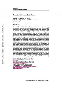
Our interest is in understanding the solution that connects these two states at infinities, i.e., shock wave analysis. 4.1. The Riemann Problem The Riemann problem is a fundamental tool for studying the interaction between waves. It has played a central role both in the theoretical analysis of systems of hyperbolic conservation laws and in the development and implementation of practical numerical solutions of such systems. The Riemann problem describes the micro structure of the shock wave. This test deals with the numerical solution of the inhomogeneous 1D × 3D Boltzmann equation for hard sphere molecules (λ = 1). In this section, we present some results for the one dimensional Riemann problem. Numerical solutions are obtained for a Knudsen number closed the fluid limit (Kn ≤ 0.01). As in [24], we consider the following macroscopic initial conditions (ρl , Vl , Tl ) = (1, 0, 1)
if 0 ≤ x ≤ 0.5,
(ρr , Vr , Tr ) = (0.125, 0, 0.25) if 0.5 < x ≤ 1.0 . (4.2) √ Let t0 the mean free time, and Tl , ρl , and Vth = 2RTl be the reference quantities. Recall that L is the domain size parameter of v i.e. v ∈ Ωv = [−L, L)3 . Then the CFL condition gives dt/t0 ≤ dx/L mean free times. The density, flow pressure and temperature profiles are shown in Figure 4.1, showing a qualitatively good agreement with Figure 3 in [24]. It can be seen that for Kn = 0.01, the profiles approach the shapes typical of continuum flows. It can be seen that the flow becomes stationary by a final time larger than 0.2 mean free times. In this case, a choice of dx = 0.5l0 is made. For smaller values of Kn ≤ 0.01, i.e., close to continuum flow, the numerical method is noticeably slow. In order to maintain good accuracy and to reduce the effect of the splitting error for close to stiff problems, a smaller value of dt is taken than required by the CFL condition. This results in a slow march in time, and thus it typically takes longer to reach the stationary state. 4.2. Shock Due to a Sudden Change in Wall Temperature As an example showing the formation of a shock wave and its propagation, we consider a semi-infinite expanse (x1 > 0) of a gas bounded by a plane wall at rest with temperature T0 at x1 = 0. Initially, the gas is at equilibrium with the wall at pressure p0 and temperature T0 . At
451
Shock and Boundary Structure Formation for Boltzmann Transport Equation
1.2
1.2
1
1
t/tr = 0 t/tr = 0.15
0.6
0.8
Density
Temperature
0.8
0.4
0.4
0.2
0.2
0 -0.2
0
0.2
0.4
0.6
0.8
1
1.2
x/xr
t/tr = 0 t/tr = 0.15
0.6
0 -0.2
0
0.2
0.4
0.6
0.8
1
1.2
x/xr
Temperature Profile
Pressure Profile
1.2
1
Density
0.8
t/tr = 0 t/tr = 0.15
0.6
0.4
Fig. 4.1. Riemann problem: temperature, pressure and density profiles for Kn = 0.01 at t = 0.15.
0.2
0 -0.2
0
0.2
0.4
0.6
0.8
1
1.2
x/xr
Density Profile
time t = 0, the temperature of the wall is suddenly changed to another value T1 and is kept at T1 for subsequent time. The time evolution of the behavior of the gas is studied numerically on the basis of the fully nonlinear Boltzmann equation with Maxwell type boundary conditions (2.21), for the case of diffuse-reflection condition on the wall with full accommodation coefficient α = 1 (Figure 4.2). As the reference length Xr , we take l0 the mean free path of the gas in the equilibrium state √ at rest with density ρ0 = p0 /RT0 and temperature T0 . We take l0 / 2RT0 as the reference time tr and use Eq. (2.3). Typically, when considering a flow that is uniform in a particular velocity direction, the Boltzmann equation can be reduced to a system of equations by integrating the distribution function in respective velocity direction(s) to get a set of marginal distributions. The proposed algorithm in this paper relies on the weak form for its derivation. But, such a weak form is not available for the marginal distribution. Moreover, it is a difficult task to eliminate a velocity component in the nonlinear collision integral. It is for these reasons that the conservative spectral method cannot be reduced in velocity components and the full 3-D computation in v has to be performed. For the purpose of analysis, the marginal distribution R function (g(x1 , v1 , t) = v2 ,v3 f (x1 , v, t)dv2 dv3 ) is calculated from the three dimensional velocity distribution. The marginal velocity distribution function g has a discontinuity at the corner (x1 , t) = (0, 0) of the domain (x1 > 0, t > 0) for v1 > 0. This discontinuity in g propagates in the direction of characteristic x1 − v1 t = 0, and subsequently decays owing to the collision integral on the right hand side. The direction of propagation depends on v1 . For v1 < 0, the characteristic starts from infinity where g is continuous and thus for all x1 , t remains continuous. For numerical calculations, typically a modified scheme is devised to account for this. But, it has been observed
452
IRENE M. GAMBA AND S.H. THARKABHUSHANAM
Fig. 4.2. Schematic of Maxwell reflective boundary conditions as defined in (2.21). Left side diffusivereflection. Right side specular-reflection.
that for the fully nonlinear Boltzmann equation, the standard finite-difference scheme with time splitting does an extremely good job of capturing this discontinuity. There are two cases of interest in the numerical experiment, T1 = 0.5T0 and T1 = 2T0 . For the first case where T1 = 0.5T0 , in the numerical computation of the time-evolution problem the temperature, pressure and density profiles have been shown in Figure 4.3. By sudden cooling of the wall temperature, the gas near the wall is suddenly cooled resulting in a pressure decrease there and an expansion wave propagates into the gas. The expansion wave accelerates gas towards the wall initially. As time goes on, with the decrease of temperature of gas near the wall, the suction of heat from the gas by the wall decreases and pressure becomes weaker. Thus, the gas begins to accumulate near the wall, because there is no suction on the wall. The pressure drop by cooling of the gas is not enough to compensate the gas flow. As the gas equilibrates with the wall, in the absence of condensation (no sink of mass), a compression wave develops that propagates outward and attenuates the initial expansion wave. Then, a compression wave chases the expansion wave to attenuate. This phenomenon occurs in long time. The main temperature drop of the gas occurs gradually, well after the expansion wave is passed. Next, we consider the case where T1 = 2T0 . With the sudden rise of wall temperature, the gas close to the wall is heated and accordingly the pressure rises sharply near the wall, which pushes the gas away from the wall and a shock wave (or compression wave) propagates into the gas. As times goes on, the gas moves away from the wall but there is no gas supply from the wall and the heat transferred from the wall to the gas decreases owing to the rise of gas temperature near the wall. Accordingly, the pressure decrease due to escape of the gas is not compensated by the heating and the pressure gradually decreases. As a result, an expansion wave propagates toward the shock wave from behind and attenuates the shock wave together with another dissipation effect. The main temperature rise of the gas occurs gradually well after the shock wave passed. This process is due to the conduction of heat. In the numerical computation of the time-evolution problem, the temperature, pressure and density profiles have been shown in Figure 4.4 for the region of a few mean free paths close to the wall. In Figure 4.5, the marginal velocity distribution function g is plotted for various times t/tr . We let Kn = 1, dx = 0.01l0 , dt = 0.75dx/L, and N = 16. We see that g has a discontinuity at (x1 , t). As time goes on, the position of discontinuity shifts to x1 = v1 t/tr , and the size of this discontinuity decreases due to molecular collisions (collision integral). All of the above numerical results agree extremely well with the ones obtained by Aoki, Sone, Nishino and Sugimoto [2] done for BGK models by discrete velocity algorithms. In both cases of wall temperature change, the second wave (compression wave for Twall = 0.5T0 and
453
Shock and Boundary Structure Formation for Boltzmann Transport Equation
Temperature profile when the wall temperature is decreased by half
1.4
1
0.8
1
0.8
0.6
0.6 0
10
20
30
0
10
20
30
x
x
Temperature Profile
Pressure Profile
Density Profile when wall temperature is decreased by half
1.4
Density at t = 0 Density at t = 10 Density at t = 15 Density at t = 20 Density at t= 25 Density at t= 30
1.2
density
Pressure at t = 0 Pressure at t = 5 Pressure at t = 10 Pressure at t = 15 Pressure at = 20 Pressure at t = 25 Pressure at t = 30
1.2
Pressure
Temperature
1.2
Pressure profile when the wall temperature is decreased by half
1.4 Temperature at t = 0 Temperature at t = 5 Temperature at t = 10 Temperature at t = 15 Temperature at t = 20 Te,perature at t = 25 Temperature at t = 30
1
0.8
0.6 0
10
20
Fig. 4.3. Formation of an expansion wave by an initial sudden (cooling) change of wall temperature from T0 to T0 /2. From left to right plots of time variations (in mean free time) of temperature, pressure and density, respectively.
30
x
Density Profile
1.25 1.4 t/tr = 0 t/tr = 0.005 t/tr = 0.035 t/tr = 0.07 t/tr = 0.25 t/tr = 0.5
1.2
t/tr = 0 tt/tr = 0.005 t/tr = 0.035 t/tr = 0.07 t/tr = 0.25 t/tr = 0.5
1.15
p/pr
T/Tr
1.2
1.1
1
1.05
0.8
1 0.6 0
0.5
1
0.95 -0.5
1.5
x/xr
0
0.5
1
1.5
2
2.5
x/xr
Temperature Profile
Pressure Profile
1.1
1.05
Density
1
0.95
t/tr = 0 t/tr = 0.005 t/tr = 0.035 t/tr = 0.07 t/tr = 0.25 t/tr = 0.5
0.9
0.85
0.8 -0.5
0
0.5
1
1.5
x/xr
Density Profile
2
2.5
Fig. 4.4. Formation of a shock wave by an initial sudden (heating) change of wall temperature from T0 to 2T0 . From left to right plots of time variations (in mean free time) of temperature, pressure and density, respectively.
454
IRENE M. GAMBA AND S.H. THARKABHUSHANAM
t/tr = 0.15
0.6
0.5 x/xr = 0.0 x/xr = 0.1 x/xr = 0.15 x/xr = 0.20 x/xr = 0.25 x/xr = 2.0
0.4
0.5
0.4
g(v1, x/xr)
0.3
0.3 0.2
0.2
0
0.5
1
0.1
0
-4
-2
0
2
4
6
v1
Fig. 4.5. Marginal Distribution at t = 0.5tr for N = 16.
expansion wave for Twall = 2T0 ) attenuates the first wave (expansion wave for Twall = 0.5T0 and compression wave for Twall = 2T0 ) only because the wall temperature is suddenly changed. If the wall temperature is changed gradually in proportion to the collision parameters i.e., the mean free path and mean free time then, we speculate that only the first wave would be propagating into the gas and there would be no ensuing second wave. We also point out that the d = 3-velocity space simulation is done with N = 16, which yields numerical marginal distribution with somehow sharp edges. For a smoother numerical output, one needs to increase N the number of Fourier modes. We also point out that the Lagrangian optimization problem results in conservation but not in smoothness. Smoothness will be recover in the spectrally accurate limit for N large. These issues on approximation theory and spectral accuracy are addressed by the authors in [31]. We finally stress that the calculation of moments is very smooth and accurate when compared with the simulations in [2]. 4.3. Heat transfer Between Two Parallel Plates We consider the case of a rarefied gas between two parallel plane walls at rest: one at temperature T0 at x1 = 0 and the other at a temperature T1 = 1.5T0 at x1 = 1. Note that, in this case the distance between the two plates is taken as the reference length (l0 ). The gas molecules make diffuse reflection on the walls (Figure 4.6). The state of the gas or the velocity distribution function can be considered to be uniform with respect to x2 and x3 . The problem conditions are given below: f (x, v, 0) = M1,0,T0
(4.3)
with T0 = 1. The discretization is give as 0.05 < dˆ x/l0 = dx < 1 and dt is chosen according to the CFL condition.
(4.4)
455
Shock and Boundary Structure Formation for Boltzmann Transport Equation
Fig. 4.6. Heat Transfer Problem
Note that when considering a highly rarefied gas (Kn → ∞), such a flow becomes uniform even in the x1 direction i.e. the state of the gas is independent of x1 . We consider here the stationary flows for range of Kn between 0.1 to 4. The stationary temperature profiles for Kn = 0.1, 0.5, 1, 2, 4 have been plotted in Figure 4.7. With √larger values of Kn, we find that the temperature profiles get flatter and flatter approaching 1.5. The lack of the perfect convergence is due to the fact that a low number of Fourier modes are taken in the simulation (N = 16). The temperature profiles in Figure 4.7, left side, approach the curves shown in chapter 10 of [3]. An increase in the Knudsen number value implies that the gas is becoming more and more rarefied and that the only interactions the gas molecules have are with the walls where they exchange their temperatures. The corresponding stationary density profiles have been plotted in the right side of Figure 4.7.
4.4. Classic Shock in an Infinite Tube: Supersonic → Subsonic Flow Consider a time-independent unidirectional flow in x1 direction in an infinite expanse of a gas, where the states at infinity are both uniform and their velocity distributions are Maxwellians
1.6 Kn = 0.1 Kn = 0.5 Kn = 1.0 Kn = 2.0 Kn = 4.0
1.8 x l
1.4
Kn = 0.1 Kn = 0.5 Kn = 1.0 Kn = 2.0 Kn = 4.0
x l
rho(x/xr)
T(x/xr)
1.6 1.2
1.4
xl
xl
xl
x l
x l
x l
x l
x l
x l
x l
x l
x l
x l
x
l
x
l
x
l
x
l
x
l
x
l
1x
x
x
x
x
x
x
l
x
l
l
l
x
l
l
l
l
l
x l
x l
x l
x l
x l
x l
xl
xl
xl
xl
xl
1.2 0.8 0
0.2
0.4
0.6
0.8
x/xr
Temperature Profile
0
0.2
0.4
0.6
0.8
x/xr
Pressure Profile
Fig. 4.7. Stationary Temperature and density profiles for increasing Knudsen number values.
456
IRENE M. GAMBA AND S.H. THARKABHUSHANAM
1.6
2.8 2.6 2.4
1.4
t/tr = 0 t/tr = 0.2
1.2
Pressure
Temperature
2.2 2 t/tr = 0 t/tr = 0.2
1.8 1.6 1.4
1 1.2 1 0.8 -15
-10
-5
0
5
10
15
0.8 -15
-10
-5
0
5
x/xr
x/xr
Temperature Profile
Pressure Profile
10
15
2
1.8
Density
1.6 t/tr = 0 t/tr = 0.2
1.4
1.2
Fig. 4.8. Stationary Shock: Mach number 1.5, and Kn = 1, Maxwell type interactions.
1
0.8 -15
-10
-5
0
5
10
15
x/xr
Density Profile
with corresponding parameters as explained in the preamble for this section. That is, |v − δ1 Vl |2 ρl exp(− ), 2RTl 2πRTl ρr |v − δ1 Vr |2 f→√ ), exp(− 2RTr 2πRTr
f→√
as
x1 → −∞ ,
as
x1 → ∞ .
The Maxwellian parameters satisfy the Rankine-Hugoniot relations. Also as in [24], we take ρl , Tl , and l0 as the reference density, temperature and lengths respectively. The shock profile is best considered in the frame of reference moving with the shock in steady state. The relevant parameter for the shock is the inflow Mach number M , defined as the ratio of the inflow velocity relative to the shock and the speed of sound, M=
Vl Vl Vl =√ , =√ c γ γTl
where c is the speed of sound and γ = 35 for monatomic gases. For simple notation, the “hats” in the nondimensional notation are dropped. For the numerical computations, the inflow temperature Tl is chosen as the free parameter and ρl = 0.5. Then the rest of the parameters take the following values in terms of Tl : r 5Tl 4M 2 Vl = M, ρr = 2 ρl , 3 M +3 r (M 3 + 3)(5M 2 − 1) M 2 + 3 5Tl Tr = Tl , Vr = . 16M 2 4M 3 These are derived from the Rankine-Hugoniot relations, which give the boundary conditions under which the steady shock wave can be observed.
Shock and Boundary Structure Formation for Boltzmann Transport Equation
457
When discussing shock structure, one often looks at the entropy production in the shock. Such an analysis shows that the entropy must grow across the shock. This requirement combined with Rankine-Hugoniot relations (4.1c) produces a requirement on the inflow Mach number: µ
5M 2 − 1 4
¶3 µ
M2 + 3 4M 2
¶5 ≥1
⇒ M ≥ 1.
Thus, a shock can only be observed for Mach numbers M ≥ 1, i.e., when the inflow velocity is supersonic. The Mach number behind the shock has to satisfy r Vr Vr M2 + 3 Mr = =p = ≤ 1. c 5M 2 − 1 5Tr /3 These conditions imply that the flow velocity changes from being supersonic to subsonic in a shock, while density and temperature grow. We plot in Figure 4.8 density, temperature and pressure profiles for M = 1.5, and Kn = 1 for Maxwell type interactions.
5. Conclusion In this paper, an accurate deterministic spectral method is presented which conserves all relevant moments of the Boltzmann collision integral. The proposed method works for both the conservative (locally elastic collisions) and non-conservative (linear Boltzmann, inelastic collisions) regimes. In the existing literature on spectral deterministic methods, the proposed method for the numerical approximation of the space inhomogeneous, time dependent Boltzmann equation is the first scheme that is conservative. Typical to any spectral method, the spectral accuracy is indeed controlled by the number of Fourier modes N . This is the first spectral method of its kind that requires no modification to compute both elastic and inelastic collisions. In comparison with the known analytical results such as moment equations for the space homogeneous elastic or inelastic Boltzmann equation of Maxwell type, or Bobylev and Krook and Wu explicit solution (BKW solution), or attracting BobylevCercignani-Gamba self-similar solutions for elastic collisions in a slow down process [8, 9]), the computed numerical solutions are found to be remarkably accurate as shown in our work on the development of Spectral-Lagrangian methods for for space homogeneous models [30], section 5. The method employs a Fast Fourier Transform for faster evaluation of the collision integral. Even though the method is implemented for a uniform grid in velocity space, it can be implemented for a non-uniform velocity grid. The only challenge in this case is computing the Fast Fourier Transform on such a non-uniform grid. There are available packages for this purpose, but such a non-uniform FFT can also be implemented using certain high degree polynomial interpolation, and this possibility is currently being explored. The integration over the unit sphere is avoided completely and only a simple integration over a regular velocity grid is needed. Even though a trapezoidal rule is used as an integration rule, other integration rules like a Gaussian quadrature can be used to get better accuracy. For time discretization, a simple Euler scheme is used. The proposed method has a big advantage over other non-deterministic methods, as the exact distribution function can actually be computed instead of just the averages. The numerical results presented here for space inhomogeneous problems show the effectiveness of the presented method in solving a wide class of problems. Especially, shock structure analysis is performed for the classic stationary shock and Riemann problems. The supersonic to subsonic flow is shown for the stationary shock problem wherein the initial conditions and the
458
IRENE M. GAMBA AND S.H. THARKABHUSHANAM
states at infinity satisfies the Rankine-Hugoniot relations. Other shock structure properties are also analyzed. For the Riemann problem, it is observed that for smaller Knudsen numbers, the computed macroscopic profiles approach the ones expected for a fluid type flow. In addition, the effect of sudden change of wall temperature, that reflects gas diffusively as done in [2], is also analyzed. The results in this case are found to be in strong agreement with the results obtained with a BGK model by the means of discrete velocity (Lattice Boltzmann) methods. Our scheme is the first one that can capture the phenomena described in [2] for a simulation for the Boltzmann equation for binary interactions. We are currently analyzing the importance of N , the velocity discretizations for space inhomogeneous Boltzmann calculations, were it is possible to show spectral accuracy is compatible the Lagrange multiplier method in the approximation of the distribution density associated to the space homogeneous non-linear interaction model [31]. In the case of a space inhomogeneous spherical Boltzmann shock analysis calculation, we observe that we require ND > NS , where ND is the number of Fourier modes near discontinuity in v and NS is the number of Fourier modes near a smooth region in v. The reason is not only to make sure that we have a good spectral accuracy and convergence but also to eliminate oscillation phenomena possible due to Gibbs type phenomenon. Finally, we add that using the present computational scheme we can also simulate rapid granular flows modeled by deterministic Boltzmann solvers for inelastic hard spheres interactions. In addition, Rayleigh-Benard convective flows and Taylor-Couette flows are also being numerically studied and are part of future projects. Acknowledgements. The authors would like to thank Sergej Rjasanow for discussions about the conservation properties of the numerical method and for other comments, and Kazuo Aoki for very valuable comments on the manuscript. Both authors are partially supported under the NSF grant DMS-0507038 and 0807712. Support from the Institute of Computational Engineering and Sciences and the University of Texas Austin is also gratefully acknowledged.
References [1] R.J. Alonso and I.M. Gamba, L1 -L∞ -Maxwellian bounds for the derivatives of the solution of the homogeneous Boltzmann equation, J. Math. Pure. Appl., (9) 89:6 (2008), 575-595. [2] K. Aoki, Y. Sone, K. Nishino, and H. Sugimoto, Numerical analysis of unsteady motion of a rarefied gas caused by sudden changes of wall temperature with special interest in the propagation of a discontinuity in the velocity distribution function, Rarefied Gas Dynamics , edited by A.E. Beylich (VCH, Weinheim, 1991), 222-231. [3] V.V. Aristov, Direct Methods for Solving the Boltzmann Equation and Study of Nonequilibrium Flows, Fluid Mechanics and its Applications, 60, Kluwer Academic Publishers, Dordrecht, 2001. [4] G.A. Bird, Molecular Gas Dynamics, Clarendon Press, Oxford, 1994. [5] A.V. Bobylev, Exact solutions of the nonlinear Boltzmann equation and the theory of relaxation of a Maxwellian gas, Translated from Teoreticheskaya i Mathematicheskaya Fizika, 60 (1984), 280-310. [6] A.V. Bobylev, J.A. Carrillo, and I.M. Gamba, On some properties of kinetic and hydrodynamic equations for inelastic interactions, J. Stat. Phys., 98 (2000), 743-773. [7] A.V. Bobylev and C. Cercignani, Discrete velocity models without nonphysical invariants, J. Stat. Phys., 97 (1999), 677-686.
Shock and Boundary Structure Formation for Boltzmann Transport Equation
459
[8] A.V. Bobylev, C. Cercignani, and I.M. Gamba, Generalized kinetic Maxwell type models of granular gases, Mathematical Models of Granular Matter, 23-57, Lecture Notes in Math., 1937, Springer, Berlin, 2008. [9] A.V. Bobylev, C. Cercignani, and I.M. Gamba, On the self-similar asymptotics for generalized non-linear kinetic Maxwell models, arXiv:math-ph/0608035 (2006), to appear. [10] A.V. Bobylev and I.M. Gamba, Boltzmann equations for mixtures of maxwell gases: Exact solutions and power like tails, J. Stat. Phys., 124 (2006), 497-516. [11] A.V. Bobylev, I.M. Gamba, and V. Panferov, Moment inequalities and high-energy tails for Boltzmann equations with inelastic interactions, J. Stat. Phys., 116 (2004), 1651-1682. [12] A.V. Bobylev, M. Groppi, and G. Spiga, Approximate solutions to the problem of stationary shear flow of smooth granular materials, Eur. J. Mech. B-Fluid., 21 (2002), 91-103. [13] A.V. Bobylev and S. Rjasanow, Difference scheme for the Boltzmann equation based on the Fast Fourier Transform, Eur. J. Mech. B-Fluid., 16:22 (1997), 293-306. [14] A.V. Bobylev and S. Rjasanow, Fast deterministic method of solving the Boltzmann equation for hard spheres, Eur. J. Mech. B-Fluid., 18:55 (1999), 869-887. [15] A.V. Bobylev and S. Rjasanow, Numerical solution of the Boltzmann equation using fully conservative difference scheme based on the Fast Fourier Transform, Transport Theor. Stat., 29 (2000), 289-310. [16] J.E. Broadwell, Study of rarefied shear flow by the discrete velocity method, J. Fluid Mech., 19 (1964), 401-414. [17] H. Cabannes, Global solution of the initial value problem for the discrete Boltzmann equation, Arch. Mech. (Arch. Mech. Stos.), 30 (1978), 359-366. [18] R. E. Caflisch, The half-space problem for the Boltzmann equation at zero temperature, Commun. Pur. Appl. Math., 38:5 (1985), 529-547. [19] R. E. Caflisch and Basil Nicolaenko, Shock profile solutions of the Boltzmann equation, Commun. Math. Phys., 86:2 (1982), 161-194. [20] C. Cercignani, Recent developments in the mechanics of granular materials, Fisica matematica e ingegneria delle strutture, Bologna: Pitagora Editrice, (1995), 119-132. [21] C. Cercignani and H. Cornille, Shock waves for a discrete velocity gas mixture, J. Stat. Phys., 99 (2000), 115-140. [22] C. Cercignani, A. Frezzotti, and P. Grosfils, The structure of an infinitely strong shock wave, Phys. Fluids, 11:9 (1999), 2757-2764. [23] F. Filbet, C. Mouhot, and L. Pareschi, Solving the Boltzmann equation in nlogn, SIAM J. Sci. Comput., 28 (2006), 1029-1053. [24] F. Filbet and G. Russo, High order numerical methods for the space non homogeneous Boltzmann equation, J. Comput. Phys., 186 (2003), 457-480. [25] M. Frigo and S. G. Johnson, Fast Fourier Transform of the West, URL www.fftw.org [26] E. Gabetta, L. Pareschi, and G. Toscani, Relaxation schemes for nonlinear kinetic equations, SIAM J. Numer. Anal., 34 (1997), 2168-2194. [27] I. M. Gamba, V. Panferov, and C. Villani, On the Boltzmann equation for diffusively excited granular media, Commun. Math. Phys., 246:39 (2004), 503-541. [28] I. M. Gamba, V. Panferov, and C. Villani, Upper Maxwellian bounds for the spatially homogeneous Boltzmann equation, To Appear in Arch. Rat. Mech. Anal., 2009. [29] I. M. Gamba, S. Rjasanow, and W. Wagner, Direct simulation of the uniformly heated granular Boltzmann equation, Math. Comput. Model., 42 (2005), 683-700. [30] I. M. Gamba and Sri Harsha Tharkabhushanam, Spectral - Lagrangian methods for collisional models of non - equilibrium statistical states, J. Comput. Phys., 228 (2009), 2012-2036. [31] I. M. Gamba and Sri Harsha Tharkabhushanam, Accuracy and consistency of Lagrangian based conservative spectral method for space-homogeneous Boltzmann equation, In preparation. [32] H. Grad, Singular and nonuniform limits of solutions of the Boltzmann equation, In Transport
460
[33] [34] [35] [36] [37] [38] [39] [40] [41] [42] [43] [44] [45] [46] [47] [48] [49] [50] [51] [52] [53] [54]
IRENE M. GAMBA AND S.H. THARKABHUSHANAM
Theory (Proc. Sympos. Appl. Math., New York, 1967), SIAM-AMS Proc., Vol. I, pages 269–308. Amer. Math. Soc., Providence, R.I., 1969. M. Herty, L. Pareschi, and M. Seaid, Discrete-velocity models and relaxation schemes for traffic flows, SIAM J. Sci. Comput., 28 (2006), 1582-1596. I. Ibragimov and S. Rjasanow, Numerical solution of the Boltzmann equation on the uniform grid, Computing, 69 (2002), 163-186. R. Illner, On the derivation of the time-dependent equations of motion for an ideal gas with discrete velocity distribution, J. de Mecanique, 17 (1978), 781-796. S. Kawashima, Global solution of the initial value problem for a discrete velocity model of the Boltzmann equation, Proc. Japan Acad. Ser. A Math. Sci., 57 (1981), 19-24. H.W. Liepmann, R. Narasimha, and M.T. Chahine, Structure of a plane shock layer, Physics of Fluids, 5 (1962). T.-P. Liu and S.-H. Yu, Boltzmann equation: micro-macro decompositions and positivity of shock profiles, Commun. Math. Phys., 246:1 (2004), 133-179. L. Mieussens, Discrete-velocity models and numerical schemes for the Boltzmann-bgk equation in plane and axisymmetric geometries, J. Comput. Phys., 162 (2000), 429-466. H.M. Mott-Smith, The solution of the Boltzmann equation for a shock wave, Physical Rev. (2), 82 (1951), 885-892. C. Mouhot and L. Pareschi, Fast algorithms for computing the Boltzmann collision operator, Math. Comput., 75 (2006), 1833-1852. K. Nanbu, Direct simulation scheme derived from the Boltzmann equation in monocomponent gases, J. Phys. Soc. Japan, 52 (1983), 2042-2049. T. Van Noije and M. Ernst, Velocity distributions in homogeneously cooling and heated granular fluids, Granul. Matter., 1:57 (1998). T. Ohwada, Structure of normal shock waves: direct numerical analysis of the Boltzmann equation for hard-sphere molecules, Phys. Fluids A, 5:1 (1993), 217-234. L. Pareschi and B. Perthame, A Fourier spectral method for homogenous Boltzmann equations. Transport Theor. Stat., 25 (2002), 369-382. L. Pareschi and G. Russo, Numerical solution of the Boltzmann equation. i. spectrally accurate approximation of the collision operator, SIAM J. Numer. Anal. (Online), 37 (2000), 1217-1245. S. Rjasanow and W. Wagner, A stochastic weighted particle method for the Boltzmann equation, J. Comput. Phys., (1996), 243-253. S. Rjasanow and W. Wagner, Stochastic Numerics for the Boltzmann Equation, Springer, Berlin, 2005. H. Salwen, C. E. Grosch, and S. Ziering, Extension of the Mott-Smith Method for a onedimensional shock wave, Phys. Fluids, 7 (1964), 180-189. Y. Sone, Molecular gas dynamics, Modeling and Simulation in Science, Engineering and Technology. Birkh¨ auser Boston Inc., Boston, MA, 2007. Theory, techniques, and applications. S. Takata, K. Aoki, and C. Cercignani, The velocity distribution function in an infinitely strong shock wave, Phys. Fluids, 12:8 (2000), 2116-2127. W. Wagner, A convergence proof for Bird’s direct simulation monte carlo method for the Boltzmann equation, J. Stat. Phys., (1992), 1011-1044. S.-H. Yu, Hydrodynamic limits with shock waves of the Boltzmann equation, Commun. Pur. Appl. Math., 58:3 (2005), 409-443. Y. Zheng and H. Struchtrup, A linearization of Mieussens’s discrete velocity model for kinetic equations, Eur. J. Mech. B-Fluid., 26 (2007), 182-192.