Research, New Mexico Institute of Mining and Technology, Socorro, New Mexico 87801,. USA. M. A. MEYERS. Center of Excellence for Advanced Materials, ...
J O U R N A L OF M A T E R I A L S S C I E N C E 26 (1991) 601
611
Shock synthesis and synthesis-assisted shock consolidation of silicides L. H. YU Department of Materials and Metallurgical Engineering and Center for Explosives Technology Research, New Mexico Institute of Mining and Technology, Socorro, New Mexico 87801, USA M. A. M E Y E R S
Center of Excellence for Advanced Materials, University of Cafifornia, San Diego La Jolla, Cafifornia 92093, USA Shock-induced chemical synthesis and synthesis-assisted consolidation of high-temperature materials (silicides) were investigated. Niobium, molybdenum, and titanium powders mixed with silicon powders were chosen as reactant materials for shock-induced synthesis of silicides. In parallel experiments, these reactant materials were also respectively mixed with inert intermetallic compound powders of NbSi 2, MoSi 2, and TisSi 3 in different proportions and were shock consolidated. Shock processing was carried out using a modification of the experimental set-up developed by Sawaoka and Akashi. The shock waves were generated in the materials by the impact of a flyer plate at a velocity of 2 kmsec -1. An explosive plane-wave generator was used to initiate the main explosive charge to accelerate the flyer plate. The passage of shock waves of sufficient pressure and temperature induced a highly exothermic and self-sustaining reaction between reactant materials. The shock-synthesized intermetallic compounds and the heat of reaction enhanced bonding between inert matrix materials. The proportion of reactant powder mixtures blended with inert intermetallic materials plays a very important role in the synthesis-assisted consolidation process. Characterization of compacts was done by optical microscopy, scanning electron microscopy, and X-ray diffraction. A preliminary analysis of shock-induced chemical reactions is conducted; it predicts a 30% increase in shock pressure and shock-wave velocity over those in unreacted powders. For shock synthesis, the profuse formation of voids indicates that melting of the material occurred; in contrast, unreacted regions did not exhibit porosity.
1. I n t r o d u e t i o n Intermetallic compounds having attractive and unique properties for extended high-temperature application are being applied as structural materials [1-3]. Silicides, in particular, are intermetallic compounds suited for high-temperature applications because of their high melting point and strength retention at high temperatures. MoSi 2 has already been used as heating 9 I-4]. Shock compression processing has been applied to synthesize materials since 1961, when DeCarli and Jamieson [5, 6] synthesized diamond from rhombohedral graphite. Since then, there has been considerable research activity in materials development using this process to synthesize compounds [7-10]. This unique process can not only induce the chemical reactions between the elemental materials, but also the high pressure can produce fully dense compacts in time durations of the order of microseconds. Horie et al. [11, 12] have systematically investigated shock-induced chemical synthesis in intermetallic compounds. They analysed the effects of shock-wave passage in Ni-A1 powder mixtures in 0022-2461/91 $03.00 + .12 9 1991 Chapman and Hall Ltd.
post-shocked specimens, and classified them as follows: (a) effects of high shock-pressure and high strain rate, and (b) effects of high temperature. Once a sufficient degree of shock-induced temperature and mixing intensity are reached, highly exothermic and self-sustaining reactions can be initiated. The concept of shock-synthesis-assisted consolidation was first applied to consolidate ceramic powders by Sawaoka and Akashi [13]. They found that the consolidation of cubic boron nitride powders by simple shock comPaction alone was not sufficient to produce strong bonding between powders; therefore, they added reactant titanium, carbon, and aluminium powders to the boron nitride. The shock synthesized ceramic binder phase and heat generated were found to assist the bonding between the cubic boron nitride powders. In this research program, three intermetallic compounds, silicides of molybdenum, titanium and niobium were chosen as inert materials to be consolidated. These intermetallic compounds are brittle and hard and are similar to ceramic materials. It is difficult 601
~0
gooo
Silicon (at. % ) ~ 80
40
92,
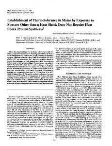
Figure 1 Phase diagrams of(a) Nb Si, (b) Mo-Si, and (c)
, ~ - 4 - ' ~ Ti-Si (from [-14]).
37.7
A
A
O
~
"",, 40
N~
fiO
'y
80
100
Silicon (xvt o/e)
(a)
st
Silicon ( a t . % )
:
L
~40~J
J, o ~coJ
b ;
Le
I..
--(MO):
E
,
n
i
ii 9 j : ,i
.
::
,, II ,y
9
,
il
i~LxJ 0
~0
40
Mo
1~oo
60
I(XI
fit,)
Silicon (wt %1
(bi
2200--
,14"I~
.
,
20L
-
~..
40
~, 2[30~
sl
Silicon !oOt.O/o) i
~
.a
,
i
,
80 ~
,
I00
L
o~
'1400
IM~,I~I 11170~
II.-
F- IO¦
?
C-
40
'I'1
(c)
(sO--
~0
Silicon (wt o/o,
s~
to consolidate these powders by conventional techniwaves can induce chemical reactions between reactant ques. The concept of shock-synthesis-assisted consolmaterials and silicides can be synthesized to assist in idation of ceramic powders was extended to the the bonding between the inert intermetallic compound present work. It was demonstrated that the shock ~ powders. 602
Detonator ~ = = ~ ~
,C/ ~,oo9171 /
I'ligh--speecl Explosive
~\
I
~o,o c9
.... !,
[ ~; l
t
~
,~
/
s,oo,c ~ ~
MomentumTrap
Figure 2 Section of "Sawaoka" fixture that contains twelve capsules (six shown in section).
2. Experimental procedures Shock-induced chemical synthesis experiments were conducted on mixtures of Nb-Si, M o - S i , and Ti-Si to determine the extent of shock induced reactions and the nature of reaction products. Shock-synthesis-assisted consolidation experiments were then conducted on p o w d e r mixtures of N b - S i - N b S i 2, M o - S i - M o S i 2 , and Ti-Si-TisSi 3. The reactant p o w d e r mixtures and intermetallics were mixed in different proportions. The powders were purchased from C E R A C ; their characteristics are listed in Table I. The composition of reactant materials was chosen based on the stoichiometric composition of the silicides: N b S i / , MoSi2, and TisSi 3. Fig. 1 shows the phase diagrams of the Nb-Si, M o - S i , and Ti-Si systems [14]. The intermetallic c o m p o u n d s are m a r k e d by arrows on the respective phase diagrams. The compositions of the different p o w d e r mixtures are listed in Table II. The powders were blended and loaded into the capsules in argon atmosphere. The cross-section of the shock processing system used in the present work is schematically shown in Fig. 2. This system is an o u t g r o w t h of the earlier system used for producing high-amplitude planar shock waves. The detonation is initiated from the
d e t o n a t o r at the top, shown in Fig. 2. A conical lens consisting of explosives with two detonation velocities was used to generate a planar wave in the main explosive charge. The flyer plate is accelerated by the detonation of the explosive charge and impacts the capsules embedded in a steel fixture. The shock waves are transmitted t h r o u g h the capsules into the powders. The m o m e n t u m trap is used to trap the reflected tensile waves in order to recover the specimens. The
T AB LE I I. Compositions of specimens and test conditions Explosive: PBX 9404 (1.27 cm thick, 20.3 cm diameter) Flyer plate: Steel (0.5 cm thick) Standoff: 1 cm Flyer plate velocity: 2 kmsecTesting temperature: Room temperature Sample Powders (wt %)
Sample Powders (wt %)
1
8
2 3 4
TABLE I. Powder sizes and sources. 5 Powder
Size (mesh)
Source
Purity (%)
Nb Mo Ti Si NbSi z MoSi2 TisSi3
-
CERAC CERAC CERAC CERAC CERAC CERAC CERAC
99.8 99.9 99.5 99.9 99.5 99.5 99.5
325 325 325 325 325 325 325
6
7
Nb (62) Si (38) Mo (63) Si (37) Ti (74) Si (26) NbSi 2 (90) Nb (6.2) Si (3.8) NbSi/(70) Nb (18.6) Si (11.4) NbSi z (50) Nb (31.0) Si (19.0)
9
10
11
12
MoSi2 (90) Mo (6.3) Si (3.8) MoSi z (90) Mo (6.3) Si (3.8) MoSi2 (90) Mo (6.3) Si (3.8) MoSi2 (90) Mo (6.3) Si (3.8) MoSi, (90) Mo (6.3) Si (3.8)
MoSiz (90) Mo (6.3) Si (3.8)
603
Shock wave
Initial capsule shape
B
F'mal capsule shape
3200
4700 K
(a) Figure 4 Size and morphology of niobium (A), silicon (B), and NbSi 2 (C) powders.
Shock wave
Initial capsule shape
LI /--~-o'~;~
B
/_
100, uPa
Final capsule shape
(b) Figure 3 (a) Maximum mean bulk temperature and (b) maximum pressure profiles for Sawaoka capsule (adapted from Norwood et al. [-15]).
impact velocity of flyer plate was around 2 km sec- 1 for this experiment. The recovered specimens were characterized by optical and scanning electron microscopy and X-ray diffraction. Only the Nb-Si and Nb Si-NbSi 2 systems are discussed in detail in this paper.
3. Results and discussion The velocity of the shock wave in the powder is lower than that in the surrounding steel capsule, thus, the shock wave planarity is lost in the powder, and the lateral effects from the capsule play an important role. The pressure and temperature distributions in the powder thus become very complicated. Norwood et al. [15] simulated the pressure and temperature contours in powder for the Sawaoka capsules by using a two-dimensional CSQ II computer hydrocode. Fig. 3 shows the maximum pressure and mean bulk temperature contours in half cross-section of compact. These profiles can provide some information as a reference for the present experiments.
3.1. S h o c k synthesis of Nb-Si p o w d e r s The packing density ofNb-Si powders was 60% of the theoretical density. The morphology of niobium, silicon, and NbSi 2 powders is shown in Fig. 4; they have 604
irregular shapes prior to compaction. The powder size, given in Table I, is below 325 mesh ( ~ 45 gin) for all materials. After compaction, the compacts were taken out from the capsule by machining. An optical micrograph of a part of the cross-section of the compaet is shown in Fig. 5. The shock-wave propagation direction is from top to bottom. Based on the etching contrast it appears that for most of the compact the Nb-Si powders had undergone complete reaction except in the regions at the top corners. Under higher magnification, dendritic structures were found in some regions, and are shown in Fig. 6a. They are marked by arrows. Profuse voids are also found throughout the reacted regions. Fig. 6b shows the needle-like (or fibrelike) structures observed adjacent or inside voids and also proves that the voids were not produced by powder pull-out during grinding and polishing. A closer view of a void shown by scanning electron microscopy in Fig. 7 clearly delineates the inside, consisting of a maze of fibres. The synthesized phase forms as fibres, which traverse the voids. These dendrites and needles result from the shock-synthesis of compounds that involves most likely a melting and resolidification sequence. Fig. 8 shows the morphology of the shock-synthesized regions in the Mo-Si and Ti-Si capsules, respectively. The features are analogous to the ones shown in Fig. 6: profuse voids and a homogeneous structure. EDS analysis showed no composition difference between the fibre-like structures and matrix. The profusion of voids and the microstructure emphasize that more heat was generated in this condition than for the reactionless consolidation of the powders (in the top corners). There are three possible causes for the large concentration of voids found. (a) Shrinkage due to solidification of melted and reacted material. (b) Tensile stresses while the synthesized material is at a high temperature and very ductile: These tensile stresses are produced by reflected waves after the passage of the main shock pulse. (c) Expansion of the entrapped gases (or gases formed during reaction) after the passage of the shock wave.
Figure 50ptical micrograph of cross-section of Nb-Si compact. (Dark region is mountingepoxy.)
In the top corners (unreacted regions), the Nb-Si powders were well compacted and interlocked together as shown in Fig. 9. Niobium and silicon powders remained unreacted probably due to lack of sufficient pressure and/or temperature to initiate the reaction in this region. The profiles shown in Fig. 3 show that the pressure and temperature in the corner regions are lower than in the other regions. The X-ray diffraction results are shown in Fig. 10. Fig. 10a corresponds to the diffraction pattern of the starting powder mixture, and Fig. 10b corresponds to that after shock synthesis. The intermetallic compound NbSiz can be easily identified in Fig. 10b. The original niobium and silicon peaks appear to have been lost, indicating almost complete reaction. A preliminary analysis of shock-induced chemical reactions was conducted for the present investigation. A complete analysis has been recently developed by
Figure 60ptical micrographsof Nb-Si compactshowingvoidsand (a) dendriticand (b) needle-shapedfeatures.
Figure 7 Scanningelectron micrograph of void.
605
Figure 9 Micrographs of unreacted regions in Nb-Si system.
Horie and Kipp [16], but the simple analysis suffices for the purposes of this work. The basic equation of energy conservation was modified by adding an energy of reaction term. The assumptions of heat of reaction independent of pressure, zero volume change (with reaction), and no melting are implicit in this equation E2 -
Figure 80ptical micrographs of(a) Mo-Si and (b) Ti-Si compacts showing voids.
S1(111)
~1b(110)
Eoo
=
89
-
V ) + ER
(1)
where ER is the energy of reaction at constant volume. The thermodynamic state after a complete reaction can be determined by assuming steady-state. Fig. 11 shows schematic Hugoniot pressure-volume curves for the solid material, the powder, and the powder with reaction. The curve for the reacted powder is
Nb(211)
Si(220) Si(422) Nb(220)
la) NbSi2(111) NbSI (102) . . . .
I
I
I
I
I
10
2o
3o
4o
50
Nb - Si (wt %)
Figure 16 Void concentration plotted against N b - S i weight percentage.
Acknowledgements This research was sponsored by McDonnell Douglas Research Laboratories and by the National Science Foundation Materials Processing Initiative (latter stages). The support provided by Dr C. Whitsett and P. Meschter is gratefully acknowledged. The capable help of Mr T. Gould in setting up the experiments is 610
References 1. 2. 3. 4. 5. 6. 7.
8. 9. 10.
J . H . W E S T B R O O K , Metall. Trans. 8A (1977) 1327. H . A . LIPSITT, D. S H E C H T M A N , and R. E. S C H A F R I K , ibid. 6A (1975) 1991. D. S H E C H T M A N , M. J. B L A C K B U R N and H. A. LIPSITT, ibid. 5A (1974) 1373. Z . A . M U N I R , Ceram. Bull. 67 (1988) 342. P . S . DECARLI, US Patent 3238019 March, (1966). P . S . DECARLI and J. C. J A M I E S O N , 133 (1961) 821. S.S. BATSANOV, A. A. DERIBAS, E. V. D U L E P O V , M. G. E R M A K O V and V. M. K U D I N O V , Comb. Expl. Shock Waves USSR 1 (1965) 47. A . N . D R E M I N and O. N. BREUSOV, Russ. Chem. Rer. 37 (1968) 392. R.A. G R A H A M , B. M O R O S I N , E. L. V E N T U R I N I and M. J. CARR, Arm. Rer. Mater. Sci. 16 (1986) 315. Y. K I M U R A , Jpn. J. Appl. Phys. 2 (1963) 312.
Nbl 110)
NbSi2(112) NbSi2 (101) Si(111)
NbSi2(102)
NbSi2 (111) Si(220 NbSi2 (003)
Nb(211)
t N%%l
NbSi2 (100)
J~
~
Si(311) Nb(200) NbSi2 NbSi2 L ~
/
] ~
NbSi2 (302) j Nb(220)
Si!422) t rI
LJLmJL~y
(o)
(b)
5~ co,
(d)
2'0
3tO
4LO
I
I
_
50 60 7 IO Diffraction ang[e~ 28 (deg)
I
80
J
90
Figure 17 X-ray diffraction patterns of Nb-Si NbSi2 powders (a) before (Nb 31 wt %, Si 19 wt %, NbSi2 50 wt %) and (b) (Nb 6.2 wt %, Si 3.8 wt %, NbSi z 90 wt %), (c) (Nb 18.6 wt %, Si 11.4 wt %, NbSi 2 70 wt %) and (d) (Nb 31 wt %, Si 19 wt %, NbSi 2 50 wt %) after synthesis and consolidation.
11.
Y. HORIE, R. A. GRAHAM and I. K. SIMONSEN, Mater.
17.
Lett. 3 (1985) 354. 12. 13. 14. 15.
16.
I . K . SIMONSEN, Y. HORIE, R. A. GRAHAM and M. J. CARR, ibid. $ (1987) 75. A. B. SAWAOKA and T. AKASHI, US Patent 4655830 (1987). T. tl. M AS SA LS K I "Binary Alloy Phase Diagrarns" (American Society for Metals, Metals Park, Ohio, 1986). F.R. NORWOOD, R. A. GRAHAM and h. SAWAOKA, in "Shock Waves in Condensed Matter", edited by Y. M. Gupta (Plenum, New York, 1986) p. 837. Y. HORIE and M. J. KIPP, J. Appl. Phys. 63 (1988) 5718.
i8. 19. 20.
M. YOSHIDA, Mixture Program, Report, Center for Explosives Technology Research, New Mexico Institute of Mining and Technology, Socorro, New Mexico, 1986. L.V. ALTSHULER, Sov. Phys. 8 (1965) 52. M.A. MEYER S and S. L. WANG, Acta Metall. 36 (1988) 925. O. KUBASCHEWSKI and C. B. ALCOCK, "Metallurgical Thermochemistry" (Pergamon, New York, 1979).
Received 26 July 1989 and accepted 19 February 1990
611