This document describes the Mini-MIPS design project which is part of course ....
You are given VHDL description of a Mini-MIPS system consisting of Mini-MIPS.
ETIN01 - Digital IC-project & Verification (HT2∼VT2 2011/2012) Mini-MIPS design project v.1.1
Short project description This document describes the Mini-MIPS design project which is part of course ETIN01 “Digital IC-project & Verification” conducted at EIT, LTH. Mini-MIPS is a 32-bit RISC with a simple instruction set similar to the MIPS instruction subset considered in chapter 4 of the textbook: D.A. Patterson & J.L. Hennessy, “Computer Organization and Design The Hardware/Software Interface, fourth edition.” (Chapters 5 and 6 in the third edition) The idea of this project based course is to guide students through a simple microprocessor design, in order to get a thorough understanding of the basic concepts taught throughout the preceding course EITF20 “Computer Architecture”. Hence, functional richness of the CPU design is not the primary goal in this course. With the aid of SPIM assembly language simulator, ModelSim SE simulator, ASIC design tools, and FPGA development board, students in the course will: • Design an executable specification of the Mini-MIPS (Task 1); • Design a simple 5-stage pipelined implementation of the Mini-MIPS (Task 2); • Synthesize and Place & Route the pipelined Mini-MIPS in standard ASIC design flow using 130 nm low power CMOS cells (Task 3); • Verify the pipelined Mini-MIPS in FPGA development board (Task 4); • Integrate the pipelined Mini-MIPS with a console I/O peripheral (Task 5); • Adding a memory hierarchy to the pipelined Mini-MIPS; (Task 6 & 7); • Design and implement an extended instruction set to use MipsIt GCC C compiler (Task 8). Prerequisite courses to the Mini-MIPS design project are EITF35 “Introduction to Structured VLSI Design” and EITF20 “Computer Architecture”, where the VHDL language, ModelSim simulator, as well as the background knowledge on computer architecture have been acquainted. Standard ASIC design flow including both hardware integration, synthesis, and place & route have been introduced in earlier laboratory exercises of this course. This project is composed of two parts and is correspondingly evaluated with two different grades. Task 1, 2, 3 and 4 are mandatory in the project, and students will get grade 4 after completing the tasks. For getting a higher grade (grade 5), students should complete one of the optional assignments among three choices: Task 5, or Task 6 & 7, or Task 8.
1
Contents 1 Introduction
3
2 Mini-MIPS specification 2.1 Instruction set . . . . . . . . . . . . . . . . . . . . . . . . . . . . . . . . 2.2 System structure . . . . . . . . . . . . . . . . . . . . . . . . . . . . . . . 2.3 Bus protocol . . . . . . . . . . . . . . . . . . . . . . . . . . . . . . . . .
3 3 3 4
3 Using SPIM for the Mini-MIPS project 3.1 Introduction . . . . . . . . . . . . . . . . . . 3.2 Memory map and initialization . . . . . . . . 3.3 Loading program data into the VHDL model . 3.4 Virtual and bare machine . . . . . . . . . . .
. . . .
6 6 6 7 7
. . . .
8 8 8 10 10
4 Compulsory tasks 4.1 Task 1: Single cycle behavioural specification 4.2 Task 2: Five stage pipeline implementation . 4.3 Task 3: ASIC synthesis and place & route . . 4.4 Task 4: FPGA verification . . . . . . . . . .
. . . . . . . .
. . . . . . . .
. . . . . . . .
. . . . . . . .
. . . . . . . .
. . . . . . . .
. . . . . . . .
. . . . . . . .
. . . . . . . .
. . . . . . . .
. . . . . . . .
. . . . . . . .
. . . . . . . .
. . . . . . . .
5 Overview of design files
11
6 Optional tasks 6.1 Task 5: Adding a console I/O peripheral . . . . 6.2 Task 6: Adding a memory interface . . . . . . 6.3 Task 7: Adding an instruction and/or data cache 6.4 Task 8: Using the MipsIt GCC C Compiler . .
2
. . . .
. . . .
. . . .
. . . .
. . . .
. . . .
. . . .
. . . .
. . . .
. . . .
. . . .
. . . .
. . . .
. . . .
12 12 12 12 12
1 Introduction Mini-MIPS is a 32-bit RISC with a simple instruction set similar to the MIPS instruction subset considered in chapter 4 in the textbook: D.A. Patterson & J.L. Hennessy, “Computer Organization and Design - The Hardware/Software Interface, fourth edition” Morgan Kaufmann, 2008 (Chapters 5 and 6 in the third edition). The Mini-MIPS 1.0 implements a true subset of the MIPS I instruction set architecture used in the MIPS R2000. Like the real MIPS, the Mini-MIPS CPU operates with separate instruction and data memories and has a 5-stage pipeline with register forwarding, delayed branches and delayed load. You are given VHDL description of a Mini-MIPS system consisting of Mini-MIPS CPU template (which you will have to complete), a clock generator, and two instances of a memory entity: the instruction memory and the data memory. Your tasks will be to specify (task 1), design and implement in VHDL (task 2), synthesize (task 3), and verify (task 4) the Mini-MIPS CPU, simulate the system and run small test programs to verify the functionalities. You may also choose to do any of the optional tasks (task 5, 6, 7, 8) in order to get a higher grade. We use the PC-version of SPIM to develop assembly language programs and to translate these into binary machine code. The VHDL model of the memory entity is capable of extracting the binary image of a program and its data from a log-file saved from SPIM and load it into the memory entity. In this way you can execute programs developed using SPIM on your VHDL model of the Mini-MIPS system.
2 Mini-MIPS specification 2.1 Instruction set Mini-MIPS is a 32-bit RISC processor with 32-bit instructions and 32-bit data. The instruction and data memory address space is 232 bytes, and only word-aligned addressing is supported in the Mini-MIPS instruction subset. Mini-MIPS has 32 general purpose 32bit registers R[0:31]. Two registers are special: R[0] contains the constant 0 (hardwired) and writes are ignored; R[31] is used to hold return addresses in case of procedure calls (the jal-instruction). The Mini-MIPS instruction formats are defined in Fig. 1 and the instruction set is defined in Table 1.
2.2 System structure The Mini-MIPS CPU uses separate instruction and data memories. This basic configuration is shown in Fig. 2(a). The separate instruction and data memory interfaces of the Mini-MIPS CPU provide significant freedom in designing the memory system. Fig. 2(b) shows a simple low-cost system with only one single main memory module, and figure 3(c) shows a high performance system with separate instruction and data caches and a single main memory module. Notice also that the main memory bus used in Fig. 2(b) and (c) can be different from the one used by the Mini-MIPS CPU.
3
31
26 25
21 20
16 15
R-type
Opcode
Rs
Rt
I-type
Opcode
Rs
Rt
J-type
Opcode
11 10 Rd
6 5
Shamt
0
Function
Immediate/Offset Target
Figure 1: Mini-MIPS instruction formats.
MiniMIPS
Bus Interface
I-Mem MiniMIPS D-Mem (a)
Mem
(b)
Bus Interface
I-Cache MiniMIPS D-Cache
Mem
(c)
Figure 2: Different Mini-MIPS system configurations.
2.3 Bus protocol Both data and instruction memory interfaces of the Mini-MIPS use the same protocol. This implies that I-Mem and D-Mem in Fig. 2(a) can be modelled as instances of the same VHDL entity, with I-Mem initialized with instructions and D-Mem with data. Fig. 3 shows signals in the memory interface and Fig. 4 shows the protocol. The interfaces are synchronous and only two transactions are provided: Write Word and Read Word. Also, the CPU indicates on a clock cycle basis if it is using the bus or not. Signals REQ and RW are used for this indication (and they are valid just after the rising edge of the clock and throughout the clock period). As there are multiple drivers on the DATA bus, different data sources need to be properly connected to avoid conflicts. Usually, three kinds of the bus connections are available: OR-, MUX-, and Tristate-bus. Here in this project, OR-bus is chosen due to the smallest hardware footprint and availability (tristate buffers are not always available, such as in FPGA). HOLD signal in the memory interface is raised when memory needs more than one clock cycle to perform the read or write transaction. In case of a write operation, the Mini-MIPS should continuously drive the bus as shown in Fig. 4.
4
Table 1: Mini-MIPS instruction set (a true subset of the MIPS R2000 instruction set). α = 0 for the single cycle Task 1 version, α = 4 for the pipelined Task 2 version. ‘&’ indicates bit-string concatenation; ‘s()’ represents data sign extension. Inst.
31-26
25-21
20-16
15-11
addu addiu subu multu
X“00” X“09” X“00” X“00”
R[s] R[s] R[s] R[s]
R[t] R[t] R[t] R[t]
R[d] R[d] X“00”
and or xor sll srl sra slt
X“00” X“00” X“00” X“00” X“00” X“00” X“00”
R[s] R[s] R[s] X“00” X“00” X“00” R[s]
R[t] R[t] R[t] R[t] R[t] R[t] R[t]
R[d] R[d] R[d] R[d] R[d] R[d] R[d]
5-0 Arithmetic X“00” X“21” R[d] Imm R[t] X“00” X“23” R[d] X“00” X“19” LO HI Logical X“00” X“24” R[d] X“00” X“25” R[d] X“00” X“26” R[d] Shamt X“00” R[d] Shamt X“02” R[d] Shamt X“03” R[d] X“00” X“2A” R[d]
sltu
X“00”
R[s]
R[t]
R[d]
X“00”
mfhi mflo lui lw sw
X“00” X“00” X“0F” X“23” X“2B”
X“00” X“00” X“00” R[s] R[s]
X“00” X“00” R[t] R[t] R[t]
j jal
X“02” X“03”
jr
X“00”
R[s]
X“00”
beq
X“04”
R[s]
R[t]
bne
X“05”
R[s]
R[t]
R[d] R[d]
Target Target X“00”
10-6
X“2B”
R[d]
Semantics = = = = =
R[s] + R[t] R[s] + s(Imm) R[s] - R[t] ((R[s] * R[t]) ≪ 32) ≫ 32 (R[s] * R[t]) ≫ 32
= = = = = = =
R[s] AND R[t] R[s] OR R[t] R[s] XOR R[t] R[t] ≪ Shamt (logical) R[t] ≫ Shamt (logical) R[t] ≫ Shamt (arithmetic) if (R[s] < R[t]) (signed) then 1D else 0D if (R[s] < R[t]) (unsigned) then 1D else 0D
=
Data Transfer X“00” X“10” R[d] = HI X“00” X“12” R[d] = LO Imm R[t] = Imm & X“0000” Offset R[t] = Mem[R[s] + s(Offset)] Offset Mem[R[s] + s(Offset)] = R[t] Unconditional jump PC = (PC + α )[31:28] & Target[25:0] & “00” R[31] = PC + 4 + α PC = (PC + α )[31:28] & Target[25:0] & “00” X“00” X“08” PC = R[s] Conditional branch Offset PC = if (R[s] == R[t]) then (PC + α +(s(Offset) ≪ 2)) else (PC + 4) Offset PC = if (R[s] 6= R[t]) then (PC + α +(s(Offset) ≪ 2)) else (PC + 4)
5
CLK
CLK
REQ RW MiniMIPS
Hold
REQ
RW
0
X
Bus not used
1
Read transaction (load word)
0
Write transaction (store word)
Memory
Addr
Description
1 Data
Figure 3: Mini-MIPS memory interface (used for both I-Mem and D-Mem). CLK
REQ
RW
Hold
Addr
Data
Addr1 R 1
Addr2
Addr3
R 2
Addr4 R 3
W4
Addr5 W 5
Figure 4: Timing diagram showing read and write transactions.
3 Using SPIM for the Mini-MIPS project 3.1 Introduction We use SPIM to develop programs for the Mini-MIPS project, i.e. to simulate and debug the programs, and to translate the symbolic assembly language code into binary machine code, which is what the real hardware as well as the VHDL models of the Mini-MIPS can execute. PC-SPIM is introduced in appendix A of the Patterson & Hennessy textbook as well as in sections “Software” and “Tutorials” on the companion CD.
3.2 Memory map and initialization The Mini-MIPS implementation conforms to the memory usage conventions of SPIM and the real MIPS (P&H "COD" 3e, figures 2.17 and A.5.1): A user program must start at address 0x00400000 (the text-segment). Similarly the data-segment starts at address 0x10000000, and by default SPIM will place data at address 0x10010000 unless the .sdata or .rdata directive is followed by an address. The VHDL code modelling of the memory unit contains data structures which populate the following 3 fragments of the address space: • 0x00000000 − 0x00000017 (Initialization and jump to 0x00400000) • 0x00400000 − 0x00401ffc (Text segment, program starts at 0x00400000) • 0x10010000 − 0x10011ffc (Data segment, only dynamic data and stack) 6
At reset the program counter is set to 0x00000000, and the initialization code in the VHDL model sets up the stack pointer ($sp) & global pointer ($gp) and jumps to address 0x00400000 where your program starts. In the real MIPS as well as in SPIM, the top of the stack will start at address 0x7fffeffc, and the $sp (R[29]) will be initialized accordingly. Similarly, $gp (R[28]) is initialized to point to 0x10008000; but this is only used by a compiler and you may forget all about it for now. As the VHDL model of the memory populates only a small fraction of the address space, $sp is initialized to 0x10011ffc in the VHDL model. If your test program does not depend on these initializations, you can skip the initialization code and simply set the program counter to 0x00400000 and start your program. In a similar way SPIM may load an exception program (along with your test program) which performs similar initializations and jumps to 0x00400000 starting your program. The exception handler does much more than initializing the above registers, and it is quite complex. Therefore it is recommended that you do not load it, i.e., deselect “Load exceptions file” in the settings menu, and remember to manually set the program counter to 0x0040000 before every simulation run.
3.3 Loading program data into the VHDL model The VHDL model of the memory entity is capable of: (i) extracting the binary image of a program and its data from a log-file saved from SPIM, and (ii) loading it into the memory. In this way you can execute programs developed using SPIM on your VHDL model of the Mini-MIPS system. In practice this is handled as follows. Just after opening the assembler source file in SPIM you save a log file (File-menu, “Save Log File”). Then you copy the log file to your ModelSim project directory (where the .mpf and .vhd files are), and edit the filename in the configuration (in test1.vhd or test2.vhd) to conform with the name of the log file. Make sure that the first word of data at 0x10010000 is non-zero, or the .log file loader will fail. As explained later we provide source code for two test programs, and for these we also provide log files generated with the “Load exceptions file” setting disabled.
3.4 Virtual and bare machine SPIM supports both the virtual machine and the bare machine instruction set. SPIM is capable of expanding pseudo-instructions but it is not able to reorder instructions. When simulating the virtual machine described in Appendix A of the textbook, enable the settings: “Allow pseudo-instructions”, “Mapped I/O”; and disable “Bare machine”, “Delayed branches” and “Delayed loads”. This is how you develop test programs for the single-cycle Mini-MIPS in Task 1. When simulating the pipelined bare machine, i.e. test programs for the pipelined Mini-MIPS in Task 2, “Bare machine”, “Delayed branches” and “Delayed load” must be checked. Note that in this mode, the assembly programs must be written to account for the branch delay slot and the load-use data hazards, as SPIM is not able to reorder (reschedule) instructions by itself. Beware of placing pseudo-instructions in the branch delay slot, since they may be expanded into multiple instructions. The “quick and dirty” way to do this is to manually insert a nop instruction after every load, branch & jump instruction in the assembly source. Optimally the program instructions should be reordered 7
to place useful instructions in the branch delay slots and after load instructions. Verify that the final program runs OK with “Delayed branches” and “Delayed load” enabled in SPIM, before running the program on your pipelined Mini-MIPS.
4 Compulsory tasks 4.1 Task 1: Single cycle behavioural specification Your first task will be to write a top-level behavioural specification of the Mini-MIPS CPU (as abstract, short and precise as possible). You will be given a test bench corresponding to the system structure shown in Fig. 2(a). The CPU architecture body includes the dataand instruction memories in the form of two arrays of 32-bit words. The “memories” are initialized by reading a test program from a text file. The filename is a generic and it is specified in the configuration for the test bench. This makes it straightforward to run different programs on the VHDL model of the Mini-MIPS. The only thing missing in this model is the VHDL code specifying the behaviour of the CPU entity. The specification should be a single cycle model (i.e. without pipelining, delayed branch, delayed load, and register forwarding). An overview of the files given to you is found in Section 5. We provide you with two test programs, one for computing Fibonacci numbers and one for computing square-roots. These two programs will NOT test the CPU completely. To test all instructions in the instruction set you will need to develop additional test programs. Try to use each instruction in a few different ways so that all parts of the CPU get tested. At reset your Mini-MIPS should start fetching instructions from address 0x00000000 which contains a small start-up program. You can bypass this for debugging purposes and start from 0x00400000 if you need to. A) Write a behavioural specification of the Mini-MIPS CPU and run the two test programs in the VHDL simulator. NB: Make sure to select VHDL-93 in the simulator. B) Write a test program that tests all instructions in the Mini-MIPS instruction set. Compare the behaviour of your Mini-MIPS with SPIM.
4.2 Task 2: Five stage pipeline implementation Your next task is to make an implementation-like behavioural model of the Mini-MIPS CPU with a 5-stage pipeline (IF, ID, EX, MEM, WB), and the necessary register forwarding needed to resolve data hazards in the pipeline. Your CPU should work with external memory modules operating according to the timing diagram in Fig. 4. Do not forget to support the HOLD signal. You will be given a VHDL-model of a memory module, and a test bench instantiating a system composed of a clock generator, your CPU, and two memories. The memories are loaded from text files specified in the configuration. Unlike the example in chapter 6 in the textbook, your Mini-MIPS implementation must have a branch delay slot of only one instruction, similar to the MIPS I ISA’s “delayed branches”. This means that calculation of branch conditions and updating of the PC should be done in the ID-stage of the pipeline. This implies that register forwarding
8
Figure 5: Structuring your VHDL model into processes. Process P1 contains both combinational and sequential logic, all outputs are registered. P2comb is pure combinational logic. P2reg is a sequential process which models a register (using flop-flops). must also be handled by the ID-stage, which again implies that the ID-stage always delivers the proper register operands to the EX-stage. Consequently, the register forwarding mechanism can be implemented by multiplexers just after the outputs of the register file. Finally we adopt the “delayed load” MIPS I ISA programming convention that no instruction will immediately access a register that is loaded by preceding lw instruction. With two memories, delayed branches, and delayed load, it is now possible to resolve all remaining hazards with a forwarding unit. A) Draw a block diagram of your 5-stage Mini-MIPS pipeline (similar to the figures in chapter 6 of the textbook 3e, for example figure 6.36 or 6.41). If you make this detailed, nice, and clear it will save you hours of VHDL code debugging. B) Write a behavioural implementation-like VHDL description of the pipelined MiniMIPS. You should organize your description into a number of processes executing concurrently within a single architecture body. You might want to describe larger components (ALU, Register file) as separate entities and instantiate them as components in the main architecture body of the CPU, as this makes testing easier. Hints: Each pipeline stage in the Mini-MIPS CPU performs a number of independent computations and you can model each of these as separate processes. Fig. 5 illustrates this idea. If the input signals to a register are needed elsewhere in the design, for example to implement forwarding, these signals must be declared and the pipeline stage fragment is modelled as a combinational and a sequential part. NB: The VHDL coding style used in Fig. 5 is synthesizable. There is a branch delay slot after unconditional jump and conditional branch instructions, i.e. bxx, bxxx, j, jr, jal, jalr instructions.
9
MicroBlaze
PLB bus 4.6
PC
IF/ID
UART Lite
Debugging data path
PC
ID/EXE
MEM/WB
EXE/MEM
Branch
PB DM
...
Register
ALU
PGM PA
...
PLB bus driver & User logics Xilinx XUP Virtex-II Pro development board
Figure 6: An illustration of the test set-up for Mini-MIPS using Xilinx MicroBlaze. C) Develop additional test programs to test register forwarding from all stages, delayed load and delayed branches. Make sure that all data paths in the CPU are tested.
4.3 Task 3: ASIC synthesis and place & route Synthesize and Place & Route Mini-MIPS in standard ASIC design flow using 130 nm low power CMOS cells. Make sure the CPU is correctly implemented by doing a backannotated timing simulation. You should also determine the longest combinational path and maximum clock frequency of your Mini-MIPS CPU, as well as the hardware resources used.
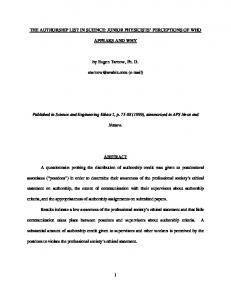
4.4 Task 4: FPGA verification Synthesize and Place & Route Mini-MIPS towards FPGA implementation in Xilinx ISE, and verify the functionality using Xilinx XUP Virtex-II Pro development board. Hints: In order to send data into and read data out from the Mini-MIPS, you should design a proper verification environment around the CPU to ease the tests. One simple approach is to use a master processor to drive the Mini-MIPS. You might for instance build a testbed in Xilinx EDK, where attach the Mini-MIPS as a slave processor and a RS232 module as a communication interface to the common PLB data bus, and drive the bus by the Xilinx MicoBlaze microprocessor. The RS232 interface can be used to transfer data between the MicroBlaze and external PC, where MicroBlaze further sends data in and out from the Mini-MIPS. The block diagram of this test set-up is illustrated in Fig. 6.
10
5 Overview of design files The following files are available. You can download them from course homepage. types.vhd: defines common types for the rest of the modules. clock.vhd: defines the clock generator. Task 1 cpu1.vhd: defines the CPU entity. It includes the necessary memory initializations. Your task is to fill in VHDL code to model the behaviour of a single-cycle Mini-MIPS CPU. The entity cpu1 has a generic parameter called programname. This parameter is used to specify which program is executed by the CPU. The file containing the program is obtained by loading an assembly file (for example fib1.s) into the SPIM simulator and then saving the log file. The log file obtained has all the information necessary for the CPU to run the program. mem1.vhd: defines the memory package. It includes procedures for accessing the instruction and data memory. test1.vhd: defines the test bench. It instantiates two components: A clock generator and a CPU (cpu1). Two different configurations are given. testfib is used to execute the Fibonacci test program and testsqrt is used to execute the square root test program. fib1.s & fib1.log: the source code and the log file for the Fibonacci test program. sqrt1.s & sqrt1.log: the source code and the log file for the square root test program. Task 2 cpu2.vhd: defines the CPU entity with ports to the external memory components. The body of the entity has been stripped off, it is your task to develop a 5-stage pipelined version of the CPU. mem2.vhd: defines the memory entity. Note that the entity has two generic parameters: filename that defines the name of a binary memory image to load; and n that defines the number of hold cycles (wait states) that the memory instance inserts at each access. By setting this parameter larger than zero, you can test that your CPU model responds correctly to the hold signal. test2.vhd: defines the test bench. Notice how PORT MAP statements are used to connect instances of the clock, cpu, and memory entities. Two different configurations are given. testfib is used to execute the Fibonacci test program and testsqrt is used to execute the square root test program. Notice how wait states are inserted for data memory accesses. Notice also that the same binary image is loaded into the instruction memory and the data memory. The reason for not separating instructions and data is that the test programs can then also be used to test the the system configurations shown in figures 3(b) and 3(c). fib2.s & fib2.log: the source code and the log file for the Fibonacci test program. fib2 differs from fib1 by using delayed branches. sqrt2.s & sqrt2.log: the source code and the log file for the square root test program. sqrt2 differs from sqrt1 by using delayed branches.
11
6 Optional tasks This section specifies a number of optional tasks. You will need to complete at least one group of tasks (Task 6 and 7 belong to one group) in order to acquire a higher grade.
6.1 Task 5: Adding a console I/O peripheral The Mini-MIPS is quite useless without any I/O communication with the external world. In this task you need to add an I/O bus interface into the Mini-MIPS, and attach at least one peripheral module onto the bus, such as the I/O switches and LEDs, RS232 interface, etc. The console I/O peripheral can be connected to the data memory interface of the MiniMIPS, with suitable address decoding for the memory-mapped registers. For example, you can allocate a range of addresses in the memory space for the peripherals, and use an I/O console to do the proper address decoding and to manage the operation of the peripherals. You may also consider to add an interrupt controller to further improve the usability of the Mini-MIPS. For example, when connecting a timer to the I/O bus, CPU needs to be interrupted upon the timer event. PCSpim is able to simulate the console hardware (Window->Console), so you can test simple console programs. Four hardware registers are memory-mapped to the address space 0xFFFF0000 ∼ 0xFFFF000F (16 bytes): 0xFFFF0000 Receiver control register. Bit 0: ready, Bit 1: keyboard interrupt enable. 0xFFFF0004 Receiver data register: Lower 8 bits: last character typed. 0xFFFF0008 Transmitter control register: Bit 0: ready, Bit 1: transmit interrupt enable. 0xFFFF000C Transmitter data register: Lower 8 bits: character to be sent.
6.2 Task 6: Adding a memory interface Design a bus interface and implement the system structure shown in Fig. 2(b) that uses only one memory module. This may be considered as the Von Neumann model. Create an entity called minimips3 that connects the CPU from task 2 to the bus interface entity. Hint: You’ll need to be able to stall the CPU, as memory in this set-up holds both instructions and data.
6.3 Task 7: Adding an instruction and/or data cache Add an instruction or data cache between the CPU and memory bus interface as illustrated in Fig. 2(c). Start your design with simple cache configurations, such as a direct-mapped write-through cache, and gradually increase the hardware complexity.
6.4 Task 8: Using the MipsIt GCC C Compiler MipsIt is a simplified GCC C cross-compiler for MIPS, with a Windows interface. By extending the instruction set to include the instructions listed in Table 2 and Table 3, it is possible to compile C-programs and execute them on the Mini-MIPS. The following
12
describes how to generate an assembly language file for SPIM. MipsIt software can be downloaded from the course homepage. Locate and run “MipsIt.exe” in the bin directory of the place MipsIt is installed. To begin select “File->New” in the menu and create a new “C(minimal)/Assembler” Project. Create a new C file (or add an existing). When the C file is opened, select “Build->View Assembler” to compile the C program into readable MIPS assembly code. Save the assembler code in a .s file and load it in SPIM. Note that GCC does not know about delayed load and delayed branches, so to run the code in SPIM, “delayed load” and “delayed branches” must be disabled. To use the GCC output with the pipelined Task 2 MiniMIPS, you must manually modify the assembly code as described above, e.g. reschedule your code or insert nop instruction to utilize the delayed slot. Other guidelines for using GCC with Mini-MIPS are listed below: • No C libraries are available for Mini-MIPS, so you’ll have to do without and so on. • Since the Mini-MIPS does not include instructions for loading and storing bytes and half-words, the char and short data types cannot be used, just use the int type for everything. • Mini-MIPS does not include the div instructions, so the C operators ‘/’ and ‘%’ should only be used with constants. • Q: What is _main()? it doesn’t exist! A: The MipsIt C compiler will insert a call to _main() to do some initialization before running your program. Easy fix: define it as an empty function: void _main(void) {} • Q: Why does my program (e.g. sqrt1.s) read from the stack? A: PCSpim inserts some C startup code before your program, just let it run and your program will eventually start at address 0x00400024. To disable this, change .text in “sqrt1.s” to .text 0x00400000 and the startup code will not be there.
13
Table 2: Extended Mini-MIPS instruction set supporting the MipsIt GCC C compiler. Extended instructions are shown in bold. α = 4 for the pipelined processor. ‘&’ indicates bit-string concatenation; ‘s()’ represents signed extension; ‘us()’ represents unsigned extension. Inst.
31-26
25-21
20-16
15-11
addu addiu subu multu
X“00” X“09” X“00” X“00”
R[s] R[s] R[s] R[s]
R[t] R[t] R[t] R[t]
R[d] R[d] X“00”
10-6 5-0 Arithmetic X“00” X“21” Imm X“00” X“23” X“00” X“19”
and or xor sll srl sra slt
X“00” X“00” X“00” X“00” X“00” X“00” X“00”
R[s] R[s] R[s] X“00” X“00” X“00” R[s]
R[t] R[t] R[t] R[t] R[t] R[t] R[t]
R[d] R[d] R[d] R[d] R[d] R[d] R[d]
sltu
X“00”
R[s]
R[t]
nor andi ori xori sllv srlv srav slti
X“00” X“0C” X“0D” X“0E” X“00” X“00” X“00” X“0A”
R[s] R[s] R[s] R[s] R[s] R[s] R[s] R[s]
R[t] R[t] R[t] R[t] R[t] R[t] R[t] R[t]
sltiu
X“0B”
R[s]
R[t]
Semantics R[d] R[t] R[d] LO HI
= = = = =
R[s] + R[t] R[s] + s(Imm) R[s] - R[t] ((R[s] * R[t]) ≪ 32) ≫ 32 (R[s] * R[t]) ≫ 32
Logical X“00” X“24” X“00” X“25” X“00” X“26” Shamt X“00” Shamt X“02” Shamt X“03” X“00” X“2A”
R[d] R[d] R[d] R[d] R[d] R[d] R[d]
= = = = = = =
R[d]
X“00”
X“2B”
R[d]
=
R[d]
X“00” Imm Imm Imm X“00” X“00” X“00” Imm
X“27”
R[d] R[d] R[d] R[d] R[d] R[d] R[d] R[d]
= = = = = = = =
R[d]
=
R[s] AND R[t] R[s] OR R[t] R[s] XOR R[t] R[t] ≪ Shamt (logical) R[t] ≫ Shamt (logical) R[t] ≫ Shamt (arithmetic) if (R[s] < R[t]) (signed) then 1D else 0D if (R[s] < R[t]) (unsigned) then 1D else 0D R[s] NOR R[t] R[s] AND us(Imm) R[s] OR us(Imm) R[s] XOR us(Imm) R[t] ≪ R[s][4:0] (logical) R[t] ≫ R[s][4:0] (logical) R[t] ≫ R[s][4:0] (arithmetic) if (R[s] < s(Imm)) (signed) then 1D else 0D if (R[s] < s(Imm)) (unsigned) then 1D else 0D
R[d] R[d] R[d]
Imm
14
X“04” X“06” X“07”
Table 3: Extended Mini-MIPS instruction set supporting the MipsIt GCC C compiler, continued. Extended instructions are shown in bold. α = 4 for the pipelined processor. ‘&’ indicates bit-string concatenation; ‘s()’ represents signed extension; ‘us()’ represents unsigned extension. Inst.
31-26
25-21
20-16
15-11
mfhi mflo lui lw sw
X“00” X“00” X“0F” X“23” X“2B”
X“00” X“00” X“00” R[s] R[s]
X“00” X“00” R[t] R[t] R[t]
R[d] R[d]
j jal
X“02” X“03”
jr jalr
X“00” X“00”
R[s] R[s]
X“00” X“00”
beq
X“04”
R[s]
R[t]
bne
X“05”
R[s]
R[t]
bltz
X“01”
R[s]
X“00”
bgez
X“01”
R[s]
X“01”
blez
X“06”
R[s]
X“00”
bgtz
X“07”
R[s]
X“00”
Target Target X“00” R[d]
10-6
5-0 Semantics Data Transfer X“00” X“10” R[d] = HI X“00” X“12” R[d] = LO Imm R[t] = Imm & X“0000” Offset R[t] = Mem[R[s] + s(Offset)] Offset Mem[R[s] + s(Offset)] = R[t] Unconditional jump PC = (PC + α )[31:28] & Target[25:0] & “00” R[31] = PC + 4 + α PC = (PC + α )[31:28] & Target[25:0] & “00” X“00” X“08” PC = R[s] X“00” X“09” R[d] = PC + 4 + α (R[d] is usually R[31]) PC = R[s] (R[s] and R[d] must be different) Conditional branch Offset PC = if (R[s] == R[t]) then (PC + α +(s(Offset) ≪ 2)) else (PC + 4) Offset PC = if (R[s] 6= R[t]) then (PC + α +(s(Offset) ≪ 2)) else (PC + 4) Offset PC = if (R[s] < 0) then (PC + α +(s(Offset) ≪ 2)) else (PC + 4) Offset PC = if (R[s] >= 0) then (PC + α +(s(Offset) ≪ 2)) else (PC + 4) Offset PC = if (R[s] 0) then (PC + α +(s(Offset) ≪ 2)) else (PC + 4)
15