This paper addresses the problem of efficiently computing optimal paths of arbitrary clearance from a polygonal representation of a given virtual environment.
In Proceedings of the Eurographics/SIGGRAPH Symposium on Computer Animation, Madrid, Spain (2010) (this is the author’s manuscript - original version at diglib.eg.org)
Shortest Paths with Arbitrary Clearance from Navigation Meshes Marcelo Kallmann University of California, Merced
Abstract This paper addresses the problem of efficiently computing optimal paths of arbitrary clearance from a polygonal representation of a given virtual environment. Key to the proposed method is a new type of triangulated navigation mesh, called a Local Clearance Triangulation, which enables the efficient and correct determination if a disc of arbitrary size can pass through any narrow passages of the mesh. The proposed approach uniquely balances speed of computation and optimality of paths by first computing high-quality locally shortest paths efficiently in optimal time. Only in case global optimality is needed, an extended search will gradually improve the current path (if not already the global optimal) until the globally shortest one is determined. The presented method represents the first solution correctly extracting shortest paths of arbitrary clearance directly from a triangulated environment. Categories and Subject Descriptors (according to ACM CCS): I.3.7 [Computer Graphics]: Three-Dimensional Graphics and Realism—Animation
1. Introduction The efficient computation of free paths in virtual environments remains a central problem in many areas of computer animation, and in particular in applications related to computer games and crowd simulation systems [ST07, MH03].
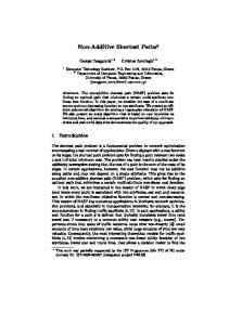
safely used to guide agents of different sizes (see Figure 1), and as a side effect, it can also be used to efficiently determine if an agent of arbitrary size is able to reach any given location of the environment. If there is no path with enough clearance to the given destination, the path planner will correctly return false.
In these applications, free paths are needed each time an agent (or a group of agents) has to navigate to specific given locations among obstacles. Paths should take into account agents of different sizes and they should be the shortest possible ones. Efficiency of computation is also of main importance, since the simulated environments are often large, with many agents, and with high frame rate requirements. Furthermore, the underlying data structure should well support the computation of reactive behaviors [Rey99] and other queries. A useful path planning module must be able to address these many needs in satisfactory ways. This paper describes a new algorithm for computing free paths among obstacles which addresses all the requirements depicted above. The presented method is able to efficiently compute paths with any desired clearance on-line, without the need of precomputed data structures dependent on a particular clearance value. The computed paths can therefore be
Figure 1: Paths are computed for agents of different sizes.
Marcelo Kallmann / Shortest Paths with Arbitrary Clearance from Navigation Meshes
In order to address both speed of computation and path optimality, the notion of local and global optimality of paths is employed in this work. The proposed algorithm first computes a locally shortest path of arbitrary clearance in O(n log n) time, where n is the number of segments describing all obstacles in the environment. This path is a highquality short and smooth path which is always suitable to be used. If additional computational time is available (and global optimality is required) an extended search procedure can then be executed, and if the current path is not already globally optimal, it will be gradually improved until the globally shortest one is determined. Another unique characteristic of the proposed method is that it only requires as underlying data structure a novel type of triangulation, called a Local Clearance Triangulation (LCT ), which is similar to the navigation meshes commonly used in many applications. The local clearance property of LCTs ensures that two local clearance values stored in each edge are sufficient for precisely determining if a disc of arbitrary size can pass trough any narrow passages of the mesh. This property is essential to correctly and efficiently determine paths of arbitrary clearance. In addition, LCTs can also be used as a flexible navigation mesh structure for many other queries, such as for determining free corridors (or channels) around paths and for computing visibility and proximity queries. In summary, the proposed approach uniquely offers many useful properties for practical applications: 1) paths can be of arbitrary clearance from obstacles, 2) high-quality locally shortest paths are computed efficiently in optimal time, 3) global optimality can be also guaranteed with additional computation, and 4) the underlying data structure is a flexible triangulated mesh useful for many navigation queries. 2. Related Work Path planning is often a key component of applications involving the navigation of characters. This is in particular the case when specific goal locations have to be attained, such as in the simulation of autonomous virtual humans [NT95, KL99] and autonomous pedestrians [MH03, ST07]. Discrete search methods such as A* [HNR07] applied to grid representations are robust and simple to implement, and thus represent a popular approach for path planning. Unfortunately the performance and quality of the obtained paths greatly depend on the chosen grid resolution and fine resolutions quickly result in too many cells to be processed in acceptable times, in particular in large environments. The logical alternative is to consider the environment delimited by polygonal obstacles and solve the problem geometrically. One approach for computing shortest paths among polygonal obstacles defined by n segments is to build and search the visibility graph [LPW79, DBCvK08] of the obstacles, what can be achieved in O(n2 ) time [OW88,
SR94]. The shortest path problem is however O(n log n) and optimal [HS97] and near-optimal [Mit93] algorithms are available following the continuous Dijkstra paradigm. However, algorithms considering an arbitrary clearance radius which are suitable for practical implementations usually solve the problem in O(n2 log n) time [Che85, LA95]. Many path planning alternatives exist if the desired path does not need to be the shortest one [Lat90, LaV06] and different solutions have been proposed specifically for computer animation applications. Examples are corridor maps [GO07, Ger10], elastic roadmaps [GSA∗ 09], multi agent navigation graphs [SAC∗ 08], and methods based on the medial axis or Voronoi diagrams [HCK∗ 00, Ger10]. Hardware acceleration has also been extensively applied [HCK∗ 00] in order to reduce the obtained computation times. These methods provide suitable paths for several applications but they do not address the specific problem of finding optimal paths with arbitrary clearance. One important characteristic of the proposed method is that it only relies on a triangulated navigation mesh. While this paper focuses on the path planning problem, the proposed triangulated mesh is also suitable for supporting the implementation of many geometric queries, such as the ones needed for handling dynamic obstacles [FS98, BLM08] and navigation behaviors [Rey99] during path execution. Previous approaches based on triangulated meshes have been proposed [KBT03,LD04], however no previous work has solved the problem of extracting optimal paths of arbitrary clearance directly from a triangulation. The proposed method solves this problem by introducing a new local clearance property which enables the precise and efficient clearance determination of paths in a triangulated mesh. As a result locally shortest paths of arbitrary clearance are efficiently computed in O(n log n) optimal time, and an extended search algorithm is also presented for determining global optimality. 3. Background and Overview Let S = {s1 , s2 , ..., sn } be a set of n input segments describing the polygonal obstacles in a given planar environment. Segments in S may be isolated or may share endpoints forming closed or open polygons. The input segments are also called constraints, and the set of all their endpoints is denoted as P. The process of constructing the proposed navigation mesh starts with the Constrained Delaunay Triangulation (CDT ) of the input segments. Let T be a triangulation of P, and consider two arbitrary vertices of T to be visible to each other only if the segment connecting them does not intercept the interior of any constraint. Triangulation T will be the CDT of S if 1) it enforces the constraints, i.e., all segments of S are also edges in T , and
Marcelo Kallmann / Shortest Paths with Arbitrary Clearance from Navigation Meshes
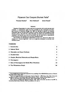
Figure 2: The left–most image shows the CDT of input obstacles. The next image shows the corresponding LCT triangulation, obtained after 5 refinements. Based on the LCT representation, locally shortest paths of arbitrary clearance are efficiently computed. The right–most image shows the globally optimal solution of the central path.
2) it respects the Delaunay Criterion, i.e., the circumcircle of every triangle t of T contains no vertex in its interior which is visible from all three nodes of t. Although CDT (S) is already able to well represent the environment and has been used before for path planning [KBT03], an additional property is proposed for enabling the efficient computation of paths with arbitrary clearance. This property is called the local clearance property and will guarantee that only local clearance tests are required during the proposed search algorithms. Whenever the local clearance property fails in CDT (S), refinement operations on the input segments are performed for enforcing it. The final obtained navigation mesh is called a Local Clearance Triangulation (LCT ) of the input segments. Note that due the possible refinement operations, the edges in S may be subdivided into smaller segments forming a new set of constrained edges Sre f . The refinement process results with LCT (S) = CDT (Sre f ). The LCT and the refinement operations are presented in Section 4. Once T = LCT (S) is computed, T can be efficiently used for computing free paths of arbitrary clearance. Let p and q be two points in R2 . A path between p and q is considered free if it does not cross any constrained edges of T . A free path will however cross several triangles sharing unconstrained edges, and the union of all traversed triangles is called a channel. A path of r clearance is called locally optimal if 1) it remains of distance r from all constrained edges in T and 2) it cannot be reduced to a shorter path of clearance r on the same channel. Such a path is denoted πr , and its channel Cr . Note that a given path πr joining two points may or not be the globally shortest path. If no shorter path of clearance r can be found among all possible channels connecting the two endpoints, the path is then the globally optimal one, it is denoted as π∗r and its channel is denoted as Cr∗ . See Figure 2 for an example. Given an LCT of the environment and two arbitrary points p, q ∈ R2 , three main algorithms are presented: • First, a channel search algorithm is proposed for finding Cr (p, q), or determining that a channel of clearance r does
not exist. This algorithm runs in O(n log n) time and is presented in Section 5. • If a channel Cr (p, q) exists, the locally optimal path πr (p, q) can be computed in linear time in respect to the number of triangles in the channel. This is achieved with an extended funnel algorithm [HS94] handling clearances, which is presented in Section 6. • If the globally shortest path is needed, an extended search procedure is responsible for comparing alternate free channels until the globally shortest path is determined. This procedure is presented in Section 7. The result is a flexible and efficient approach for path planning. Several results and performance evaluations are presented in Section 8.
4. Local Clearance Triangulation Let S = {s1 , s2 , ..., sn } be the set of input segments and T = CDT (S). Let π be a free path in T , and let t be a triangle of the channel of π, such that t is not the first or last triangle of the channel. In this case π will always traverse t by crossing two edges of t. Let a, b, c be the vertices of t and consider that the free path crosses t by first crossing edge ab and then bc. This particular traversal of t is denoted by τabc , where ab is the entrance edge and bc is the exit edge. The shared vertex b is called the traversal corner, and the traversal sector is defined as the circle sector between the entrance and exit edges, and of radius min{dist(b, a), dist(b, c)}, where dist denotes the Euclidean distance. Note that the entrance and exit edges of a traversal cannot be constrained edges of T . The proposed navigation mesh is based on a local clearance measure defined per triangle traversal. Given a traversal τabc , its sector clearance cl(a, b, c) is defined as the distance between the traversal corner b and the closest vertex or constrained edge intersecting the traversal sector. Note that due the Delaunay criterion, a and c are the only vertices in the sector, and thus cl(a, b, c) ≤ min{dist(b, a), dist(b, c)}. In case cl(a, b, c) is determined by a constrained edge s crossing the traversal sector, as illustrated in Figure 3, then cl(a, b, c) = dist(b, s). Note that if edge ac is constrained then cl(a, b, c) = dist(b, ac) and if the traversal
Marcelo Kallmann / Shortest Paths with Arbitrary Clearance from Navigation Meshes
sector.pdf sector is not margins: crossed 2.15, by a 4.55, constraint then cl(a, b, c) = 2.5, 5.4 min{dist(b, a), dist(b, c)}. s
b’
4.1. Computing LCTs c
a
b
Figure 3: If constrained edge s is the closest constraint crossing traversal sector τabc , then cl(a, b, c) = dist(b, s) = dist(b, b0 ), where b0 is the orthogonal projection of b on s. Let τabc be a traversal in T such that the adjacent traversal τbcd is possible, i.e., edge cd is not constrained. Let v be a vertex connected to c and on the same side of ac as b, and let s be a constrained edge such that s is either ac (if ac is constrained) or s and v are on opposite sides in respect to ac. In this situation, vertex v is a disturbance to traversal τabc if: 1. 2. 3. 4.
v can be orthogonally projected on ac, v is not shared by two collinear constraints, dist(v, s) < cl(a, b, c), and dist(v, s) < dist(v, c).
Note that disturbances can only occur for traversals leading to a corner transition from one side of the channel to the other side (see Figure 4). Note also that the constraint of the disturbancedisturbance.pdf may be the edge ac of the traversal and that a same traversal may have several margins: 1.45, 3.9, disturbances. 2.45, 5.1
s
b’
d’
v’ u’
a
c
b
d
Definition 2 (LCT) A LCT triangulation is a CDT triangulation with all traversals having local clearance.
v u
Figure 4: The shown traversal τabc leads to a corner transition (from b to c) and therefore may have disturbances. The dashed lines show the orthogonal projections of several vertices on s. Vertex v is a disturbance since dist(v, v0 ) < dist(b, b0 ) = cl(a, b, c) and dist(v, v0 ) < dist(v, c). Vertices d and u cannot be disturbances since dist(d, d 0 ) > dist(b, b0 ) and u is shared by two collinear constraints. With the definition of disturbances a local clearance triangulation (LCT ) can be now defined with the following definitions. Definition 1 (Local Clearance) A traversal τabc in T has local clearance if it does not have disturbances.
The proposed procedure for achieving LCT (S) is based on iterative refinements of disturbed traversals. The algorithm starts with the computation of triangulation T0 = CDT (S). A linear pass over all traversals of T0 is then performed, and all traversals detected to have a disturbance are stored in a list L. Then, for every traversal in L, the constraint s of the disturbance is refined with one subdivision point pre f in s. Note that, before a traversal is actually refined it has to be verified again for disturbances, since previous refinements may have changed the state of the current traversal. Each refinement operation is equivalent to one vertex insertion in the current CDT and can be implemented using the recursive Delaunay flips of the incremental CDT algorithm [KBT03]. Every time a constraint s ∈ S is refined, s is replaced by two new sub-segments. After all disturbed traversals in L are processed, a new (refined) set of constraints S1 is obtained. Triangulation T1 = CDT (S1 ) is the result of the first refinement iteration. T1 however is not guaranteed to be free of disturbances and therefore the process has to be repeated k times, until Tk = CDT (Sk ) is free of disturbances, in which case Sk = Sre f and Tk is the desired LCT (S). The performance of the described refinement iterations greatly depends on the location of pre f . The key is to ensure that each disturbed traversal is fixed by one refinement operation. A suitable refinement point pre f for a disturbance v in respect to τabc and constraint s can be obtained as the mid-point between the intersections of s with the circle passing by vertices b, v and u, where vertex u is the next vertex around c, when rotating from v to b, as shown in Figure 5. Note that in case of multiple disturbances, v is selected as the closest disturbance to s. The point of subdivision pre f is carefully chosen to be in a location where it will be guaranteed that both the corner of the traversal and the disturbance vertex will become connected to pre f by edges after the refinement. Based on the chosen refinement point and on the definition of considered disturbances, it can be showed that each vertex of the triangulation can, in the worst case, be a disturbance in respect to only a small number of constraints; and that since every refinement point is shared by two collinear constraints, propagations cannot occur. Therefore the total number of vertices in LCT (S) remains O(n). Figure 6 shows a step by step example of the iterative refinement algorithm. Further examples are presented in Section 8 showing that in practice the number of added vertices is usually very low. Once T = LCT (S) is computed, T can then be used to efficiently compute navigation queries, and in particular free paths of arbitrary clearance.
refpoint.pdf margins: 1.55, 3.85, 2.5, 1.3 Marcelo Kallmann / Shortest Paths with Arbitrary Clearance from Navigation Meshes
s
x1
pref
x2
a
c
b
d
u
v
s
pref a
c
b
d
u
v
Figure 5: Vertex v is a disturbance to traversal τabc and therefore constraint s is subdivided. Points x1 and x2 are the points of intersection between s and the circle passing by u, v and c. Vertex u is the next vertex around c, when rotating from v to b. The subdivision point pre f is defined as the midpoint between x1 and x2 . The refinement will connect all vertices between b and v to pre f .
Figure 7: The left image shows a CDT triangulation with an illegal path which however satisfies its local clearance tests per triangle traversal. Once the existing disturbances in the CDT are solved and the corresponding LCT is computed (right image), local clearance tests are enough to correctly detect that the channel does not have enough clearance, and a correct solution path can be determined.
fore each traversal clearance value can be pre-computed and stored in the triangulation. This reduces the local clearance test to a simple value comparison per traversal. Given a traversal τabc , the computation of cl(a, b, c) requires checking if there is a constrained edge s in the opposite side of ac in respect to b, such that dist(b, s) < min{dist(b, a), dist(b, c)} (see Figure 8-left). An efficient algorithm based on edge adjacency relations can be implemented for checking the edges “behind” ac which are closer to b than min{dist(b, a), dist(b, c)}.
Figure 6: In this example, T0 = CDT (S) has three disturbances detected in the first iteration. The blue segments connect each disturbance to its respective refinement point for clearing the traversal. In the following iteration, one disturbance is detected in T1 . The additional refinement leads to T2 , which still shows one disturbance. Finally, after 3 iterations, T3 = LCT (S).
Clearance values are precomputed and stored in the edges of the LCT . There are a total of 8 possible traversals passing by each edge. Since traversals of opposite orientation around a same corner will share the same clearance value, only 4 traversals may have distinct values. Each traversal passes by two edges (the entrance and exit edges) and thus only 2 of the 4 values have to be stored per edge. Let bc be an edge of the LCT and a and d the remaining vertices of the two triangles sharing bc (see Figure 8-right). The two values chosen to be stored at edge bc are the clearances of the traversals having precomp.pdf seclear.pdf margins: margins: bc as exit 2.15, edge:4.55, cl(a,2.5, b, c)5.4 and cl(d, c, b).2.15, 4.55, 2.5, 5.4 s
4.2. Path Clearance in LCTs The local clearance property of LCTs guarantees that a simple local clearance test per triangle traversal is enough for determining if a path πr can traverse a given channel without any intersections with constraints. Given the desired clearance radius r, πr will not have any intersections with constraints if 2r < cl(a, b, c) for all traversals τabc of its channel. Figure 7 presents an example showing that local clearance tests are not enough in CDT s but provide correct results in the corresponding LCT s. Ensuring that local tests are enough is critical for achieving efficient search algorithms. By being local, the clearance test does not depend on adjacent traversals and there-
b’
c
a
b’
s
c a
l1
l2 d
b
b
Figure 8: Left: for computing cl(a, b, c) all edges behind ac and closer to b than min{dist(b, a), dist(b, c)} are checked to be constrained. Right: the precomputation of clearances will store at edge bc two values: cl(a, b, c) and cl(d, c, b). Clearance at End Points It can be shown that local clearance tests per triangle are enough for determining if paths can traverse triangles, however the end points require additional tests. Even when a complete triangle traversal is legal
Marcelo Kallmann / Shortest Paths with Arbitrary Clearance from Navigation Meshes
according to the local clearance test, the clearance may not be enough if the path has to start or end at a given fixed point inside the triangle. See Figure 9 for an example.
Figure 9: In this LCT, the triangle containing the right end point of the path has enough clearance for the full traversal but not when connected to the fixed point. Additional departure and arrival clearance tests are therefore needed to make sure that a given path can depart or arrive to the given specific end-points. Let p be the starting path point and let bc be the first edge to be traversed by the path, as shown in Figure 10. Let t1 and t2 be the two tangent segments to the circle connecting to b and c. All vertices lying between the two tangents are disturbances to the path departure across edge bc. For determining if there is enough departure clearance, each disturbance v is checked to have deptest.pdf distance greater2.5, than4.6, 2r in2.45, respect to constraints on the other margins: 3.75 (abc size: 8.45’’x8.45’’) side of the circle entrance. This test will determine that the departure edge shown in Figure 9 is not possible.
a
t2
p
c v
t1 b
Figure 10: The departure (or arrival) test detects all vertices between tangents t1 and t2 and checks if they represent a disturbance. Departure and arrival tests can be efficiently performed on-line since they only depend on local tests. One useful property is that these disturbances can only occur on one side of an entrance at each time. Another special case which has to be dealt with is when both points p and q of the query lie in a same triangle t. In this situation a special capsule test is required in order to verify if there is enough clearance between the two points for a direct path inside t. These tests are similar to the entrance and arrival tests. 5. Channel Search Once the LCT of the planar environment is available, a graph search can be performed over the adjacency graph of the triangulation in order to obtain a channel Cr with enough clearance and connecting the two input points p and q. The process first locates the triangle tinit containing p,
following the oriented walk search method described in [KBT03]. The departure tests are then verified in order to determine the departure edges which have enough clearance. An A* search then starts for each departure edge. The search continuously expands triangle traversals from the current lowest cost edge until the triangle containing q is found. Note that triangle traversals are only accepted if the clearance of the respective traversal (which is precomputed in the LCT) is greater or equal to 2r, in order to guarantee the desired path clearance. Note also that the search expansion will only allow expansions to triangles which were not already reached by previous expansions of the search. This ensures the O(n log n) running time of the search and is efficiently implemented by marking triangles at each search expansion. It can be shown that marking is acceptable since LCTs will ensure that a single long thin triangle cannot be the only access to more than one corridor, in which case marking the thin triangle would incorrectly make non-visited regions of the triangulation inaccessible. The search will therefore expand valid traversals and return a valid channel Cr if one exists. However there are no guarantees that the returned channel will contain the globally optimal path. The cost function used to prioritize the A* search expansion is key to ensure that good channels are obtained. Different cost functions based on the adjacency graph of the triangulation can be defined to prioritize the search. The obtained A* search will be actually equivalent to a shortest path search in the graph defined by the cost metric. This graph does not need to be created in advance but the costs (or lengths) of its edges are computed on-line during the search expansion. Figure 11 shows the expanded branches of four different graphs, each obtained according to four different cost metrics. The segments in black represent the expanded edges, and the segments in blue represent the expansion front at the moment of reaching the goal point. The first metric used in Figure 11 selects the centroid of each triangle as the reference point for each triangle traversal. Therefore each time a triangle traversal is expanded, the expansion cost accounts for the length of the straight segment connecting the centroids of the traversed triangles. It is possible to notice that this metric creates many unnecessary zigzags which will make the length of the solution branch of the graph to be much larger than the length of the locally optimal path passing by the solution channel. The second metric shown in Figure 11 reduces this disparity by using the mid point of each traversed edge as the reference point of traversals. The third metric incorporates a visibility criterion. Let e be the current edge being traversed. If the segment connecting q to the reference point of the previous traversal intersects e, then the intersection point is taken, otherwise the vertex of e which is closest to q is taken. This improvement guarantees that Cr∗ will always be found if π∗r is a straight line connecting the initial and final
Marcelo Kallmann / Shortest Paths with Arbitrary Clearance from Navigation Meshes
points. This is an important improvement since it guarantees that straight line solutions are not missed. The fourth metric further improves the third one by ensuring that each taken point in e has distance r from the endpoints of e. The fourth metric has shown to be a simple and efficient cost computation procedure for obtaining high-quality channels, which are furthermore often the ones already containing the globally optimal path. As an example, the locally optimal solutions shown in Figure 2 were computed with the third metric. When the fourth metric is used, the local solution obtained for the central path becomes equal to its global solution. The fourth metric also shows to be superior in the example of Figure 11.
Note that the channel is already represented as a triangulated simple polygon. This is important since it allows the direct application of the efficient funnel algorithm [Cha82, LP84, HS94], which is able to determine the shortest path inside a triangulated simple polygon in linear time. Although the funnel algorithm only addresses shortest paths for points, the needed extensions for taking into account desired clearances are now presented. Given clearance r, whenever path πr has to make a turn inside the channel it will follow a circle of radius r centered at one vertex of the channel. Therefore the final obtained path will be a sequence of straight segments and circle arcs. Let cr (p) denote the circle centered at point p of radius r, and let v1 and v2 be two vertices of the channel. Note that a vertex will be either at the top or at the bottom boundary of the channel and circles centered at the vertices will have an interior and an exterior side. Finally, let τr (v1 , v2 ) denote the segment tangent to circles cr (v1 ) and cr (v2 ), such that the segment is tangent to the interior sides of the circles. Note that for each given pair of circles, τr identifies only one interior tangent (see the tangents in Figure 12 for examples). If tangent τr (p, v) is in respect to a point p which is not a vertex of the triangulation, the tangent will start at p and will be only tangent to the circle centered at vertex v. Given initial and final points p and q, path πr (p, q) will therefore be composed by τr tangents and circle arcs centered at the channel vertices. If v1 and v2 are vertices of the channel, consider the sub-path πr (v1 , v2 ) to be the shortest path in the channel starting tangent to cr (v1 ) and ending tangent to cr (v2 ).
Figure 11: The images show different channels obtained according to different search metrics. Each metric results in a different solution path. The path obtained by the fourth metric (bottom image) is the global optimal. More complex cost rules (for example even including some backtracking) can be devised in order to improve the cost function, however it is not possible to obtain a metric which will always return globally optimal solutions. This happens because a single triangle may overlap with more than one region of the shortest path map of p [Mit93], while the LCT representation is a generic planar subdivision which is independent of the source query point. 6. Paths from Channels Once the channel Cr containing the solution path is determined, Cr is guaranteed to contain enough clearance and the problem is reduced to computing path πr inside Cr .
The proposed r-funnel algorithm can now be described as follows. As shown in Figure 12, let p be the starting point of the path and u and v be at the extremities of the funnel (or at its door). Paths πr (p, v) and πr (p, u) may travel together for a while, and at some vertex a they diverge and are concave until they reach circles cr (u) and cr (v). The r-funnel is the region delimited by segment uv and the concave chains πr (a, v) and πr (a, u), and a is its apex. The vertices of the funnel are stored and processed in a double-ended queue Qd . Figure 12 illustrates the insertion process of a new vertex w. Points from the v end of Qd are popped until b is reached, because tangents τr (a, b) and τr (b, w) form a concave chain, and the tangents in respect to the popped points not (see for instance that τr (b, c) and τr (c, w) do not form a concave chain). The symmetrical process is performed if the new vertex is between the extended edges of the upper concave chain of the funnel. Whenever the apex of the funnel is popped during the process, it becomes part of the path so far and the funnel advances. The side of Qd to start the tests is determined according to the next triangle adjacent to the current funnel door. In Figure 12 the door is uv and the next triangle in the channel is uvw. Since this step advances the bottom part of the funnel
Marcelo Kallmann / Shortest Paths with Arbitrary Clearance from Navigation Meshes
(from v to w), Qd is processed starting from its lower end. The triangulation of the channel therefore gives the ordering for processing the vertices of the channel. The described algorithm needs however to handle one specific situation in this extended version. Let w be the current vertex being added to the funnel. When clearance values are relatively large, it may happen that cr (w) will intersect the interior of the funnel, possibly generating a new internal turn that may collapse the boundaries of the funnel. For instance this will happen in degenerate cases when the funnel is reduced to its door and cr (w) intersects the door segment. This situation does not affect the overall logic of the algorithm, however, a specific correction test has to be included each time a new apex a is reached. Let v1 and v2 be the two final vertices in the path computed so far. Before a is appended to the path, the following test is verified: if v2 is at the bottom boundary of the channel, τr (v1 , v2 ) and τr (v2 , a) have to form a clockwise turn, otherwise the turn has to be in counter-clockwise orientation. If this test fails, vertex v2 is not needed and is popped from the current path. The test repeats until it is verified and a can then be appended. The final step of the algorithm happens when the final triangle of the channel is reached. At this point the goal point q on the final triangle is connected to either the apex or one of the boundaries of the final funnel in order to finally determine the shortest path in the channel, similarly to the original funnel.pdf Figure 13 illustrates an example path being funnel algorithm. margins: 2.1, 2.82, 3.35 computed in a channel by 2.25, the presented r-funnel algorithm.
7. Optimal Path Search An extended search procedure is required for when global optimality of paths is needed. First, a locally optimal path is computed and its length lc is used as an upper bound for the global optimum, similarly to a branch and bound search. The extended search does not mark traversed triangles and thus traversal expansions may overlap. In order to be able to determine which channels are allowed to overlap, instead of relying on a cost metric, each expansion front expands one independent r-funnel. Let a be the apex of a given funnel front f , and u and v be the extremities of the funnel door. Each funnel front maintains the following three values: 1) f p is the length of the path computed so far, from p to a, 2) fl is a lower bound for the length of the funnel section of path πr (from the apex to the funnel door) and is computed with dist(a, uv), 3) fu is an upper bound for the funnel section of the path, and is computed by dist(u, v) + max{dist(a, u), dist(a, v)}. In addition to maintaining these values per front, each edge of the triangulation stores the index of the funnel front reaching it with shortest f p . A priority queue Q maintains all the current fronts sorted by their f p value. At each iteration, the search removes from Q the front f exp with minimum f p value. Front f exp is then expanded by adding one more vertex to its funnel, if the expansion has enough clearance. When expanded, f exp reaches a new edge e of the triangulation. If e had been reached before by another front, let f e denote such front. The following tests are then performed: exp
u
a
p
b c
w v
Figure 12: The r-funnel algorithm. The red circles are centered at the top vertices of the funnel and the blue circles are centered at the bottom vertices. u
p
b a
w v
Figure 13: Two different instances of the r-funnel algorithm while processing one channel of the triangulation.
exp
1. If f p + fl + dist(e, q) > lc , then f exp will die since the minimum length of any πr path passing by it will be longer than the current solution path. exp exp 2. If f p + fl ≥ f pe + fue , then f exp also safely dies since the previous front reaching the same edge is guaranteed to contain a shorter path. 3. If the funnels in f exp and f e are equal (i.e. have the same exp vertices on their boundaries), f exp will die if f p ≥ f pe , e and otherwise f is marked to die next time it is selected for expansion. When f exp is not detected to die it will be reinserted in Q for a future new expansion. In case both f exp and f e are not detected to die, then a traversal overlap by two independent fronts occurs and in this case e is updated to reference exp exp f exp if f p + fu < f pe + fue . Overlaps will occur when the overlapping fronts are still competing for the optimal funnel passing by that particular region of the triangulation. Each time a front reaches the triangle containing the goal point q, the front’s path πr will replace the current path in case its length is lower than lc . In larger environments, this extended search can be significantly slower not only due the larger number of nodes expanded but also because each expansion requires many more geometric computations due the many funnels being updated. However, the proposed approach allows to obtain
Marcelo Kallmann / Shortest Paths with Arbitrary Clearance from Navigation Meshes
gradual improvements of the current path. Every time a new front with lower path length reaches the goal an improved path is returned. When all fronts are exhausted the final path obtained is the optimal one.
Figure 14: In this example, many funnel fronts are initially expanded, then in a mid stage (top-right image), most of the fronts die due a narrow passage and only three remain active. In the last iterations only two fronts are active and one of them reduces the path with an alternate last turn.
8. Results and Discussion Table 1 shows that the locally optimal search is highly efficient, obtaining paths in 3 milliseconds in environments described by 63K segments. This makes the proposed algorithm probably the most efficient approach available for achieving smooth and short paths of arbitrary clearance. Globally optimal paths require significantly more computation time, and offer only a small path reduction in average. Figures 14 and 15 exemplify how the search for the global optimum depends on the type of environment. Several results are also available in the accompanying video. These results demonstrate that locally optimal paths are perfectly suitable for character navigation, and the small difference from the global optimum can actually be used as a way to mimic the humanlike behavior of not always using the exact same path, for instance by varying the path search metric (for example among the ones in Figure11). Many extensions can be developed for customization to specific needs (application to non-flat terrains, hierarchical layers, etc). The triangulation can also be used for visibility and proximity queries by having each triangle to keep track of its agents and applying simple triangle traversals from a
Figure 15: This environment has O(n) junctions (triangles with three free edges), what increases the branching factor and the number of overlapping fronts expanded. From top to bottom, the initial path has length 32.49 and is improved 3 times: first to 32.46, then to 32.30, and finally to 32.29, reaching the global optimal.
starting triangle, up to any desired radius. While several of such extensions are left for future work, further details and proofs about the presented algorithms will be soon available in an extended version of this paper. 9. Conclusion Several new results were presented for enabling the efficient extraction of high-quality paths of arbitrary clearance from triangulations in optimal time. An extended search for the global optimum is also presented. The proposed methods are the first to correctly extract such paths from a triangulated mesh and the overall approach demonstrates many benefits for the navigation of characters in virtual environments. References [BLM08] B ERG J., L IN M., M ANOCHA D.: Reciprocal velocity obstacles for real-time multi-agent navigation. In ICRA’08: Proceedings of the International Conference on Robotics and Automation (2008). 2 [Cha82] C HAZELLE B.: A theorem on polygon cutting with applications. In SFCS ’82: Proceedings of the 23rd Annual Symposium on Foundations of Computer Science (1982), IEEE Computer Society, pp. 339–349. 7
Marcelo Kallmann / Shortest Paths with Arbitrary Clearance from Navigation Meshes
environment env1 env2 obst1k obst5k obst15k obst30k world map
n 171 313 1207 5550 14963 29198 63426
refinements 16 29 19 44 88 105 2198
LCT triangles 333 687 2455 11191 30105 58609 131247
tlocal (ms) 0.09 0.11 0.19 0.49 1.49 2.28 3.11
tglobal (ms) 0.22 0.29 1.48 13.51 62.88 206.99 401.92
lenlocal 8.75 55.8 159.6 156.4 164.5 168.1 212.0
lenglobal 8.74 55.7 159.4 156.1 164.0 167.6 210.1
Table 1: Environment env1 is shown in Figure 14, env2 is shown in Figure 1, and the world map environment is shown in the accompanying video. The remaining environments are like the one shown in Figure 15 but with varying number of obstacles. The numbers represent averages over 100 paths randomly computed. Times tlocal and tglobal are the average times in milliseconds for computing locally and globally optimal paths. Their average lengths are shown in the two right–most columns.
[Che85] C HEW L. P.: Planning the shortest path for a disc in o(n2 logn) time. In SCG ’85: Proceedings of the first annual symposium on computational geometry (1985). 2 [DBCvK08] D E B ERG M., C HEONG O., VAN K REVELD M.: Computational geometry: algorithms and applications. Springer, 2008. 2 [FS98] F IORINI L. P., S HILLER Z.: Motion planning in dynamic environments using velocity obstacles. International Journal of Robotics Research 17, 7 (1998), 760–772. 2 [Ger10] G ERAERTS R.: Planning short paths with clearance using explicit corridors. In ICRA’10: Proceedings of the IEEE International Conference on Robotics and Automation (2010). 2 [GO07] G ERAERTS R., OVERMARS M. H.: The corridor map method: a general framework for real-time high-quality path planning: Research articles. Computer Animation and Virtual Worlds 18, 2 (2007), 107–119. 2
graph. IEEE Transactions on Robotics and Automation 11, 5 (1995), 682–691. 2 [Lat90] L ATOMBE J.-C.: Robot Motion Planning. Kluwer Academic Publisher, December 1990. 2 [LaV06] L AVALLE S. M.: Planning Algorithms. Cambridge University Press (available on-line), 2006. 2 [LD04] L AMARCHE F., D ONIKIAN S.: Crowd of virtual humans: a new approach for real time navigation in complex and structured environments. Computer Graphics Forum 23, 3 (2004), 509–518. 2 [LP84] L EE D. T., P REPARATA F. P.: Euclidean shortest paths in the presence of rectilinear barriers. Networks 3, 14 (1984), 393–410. 7 [LPW79] L OZANO -P ÉREZ T., W ESLEY M. A.: An algorithm for planning collision-free paths among polyhedral obstacles. Communications of ACM 22, 10 (1979), 560–570. 2
[GSA∗ 09] G AYLE R., S UD A., A NDERSEN E., G UY S. J., L IN M. C., M ANOCHA D.: Interactive navigation of heterogeneous agents using adaptive roadmaps. IEEE Transactions on Visualization and Computer Graphics 15 (2009), 34–48. 2
[MH03] M ETOYER R. A., H ODGINS J. K.: Reactive pedestrian path following from examples. In CASA ’03: Proceedings of the 16th International Conference on Computer Animation and Social Agents (2003), IEEE Computer Society. 1, 2
[HCK∗ 00] H OFF III K. E., C ULVER T., K EYSER J., L IN M., M ANOCHA D.: Fast computation of generalized voronoi diagrams using graphics hardware. In Proceedings of the sixteenth annual symposium on computational geometry (2000). 2
[Mit93] M ITCHELL J. S. B.: Shortest paths among obstacles in the plane. In SCG ’93: Proceedings of the ninth annual symposium on computational geometry (New York, NY, USA, 1993), ACM, pp. 308–317. 2, 7
[HNR07] H ART P. E., N ILSSON N. J., R APHAEL B.: A formal basis for the heuristic determination of minimum cost paths. Systems Science and Cybernetics, IEEE Transactions on 4, 2 (February 2007), 100–107. 2
[NT95] N OSER H., T HALMANN D.: Synthetic vision and audition for digital actors. In Proc. of Eurographics (1995). 2
[HS94] H ERSHBERGER J., S NOEYINK J.: Computing minimum length paths of a given homotopy class. Computational Geometry Theory and Application 4, 2 (1994), 63–97. 3, 7 [HS97] H ERSHBERGER J., S URI S.: An optimal algorithm for euclidean shortest paths in the plane. SIAM Journal on Computing 28 (1997), 2215–2256. 2 [KBT03] K ALLMANN M., B IERI H., T HALMANN D.: Fully dynamic constrained delaunay triangulations. In Geometric Modeling for Scientific Visualization, Brunnett G., Hamann B., Mueller H., Linsen L., (Eds.). Springer-Verlag, Heidelberg, Germany, 2003, pp. 241–257. ISBN 3-540-40116-4. 2, 3, 4, 6 [KL99] K UFFNER J. J., L ATOMBE J.-C.: Fast synthetic vision, memory, and learning models for virtual humans. In CA’99: Proceedings of Computer Animation (1999), IEEE. 2 [LA95] L IU Y. H., A RIMOTO S.: Finding the shortest path of a disk among polygonal obstacles using a radius-independent
[OW88] OVERMARS M. H., W ELZL E.: New methods for computing visibility graphs. In SCG ’88: Proceedings of the fourth annual symposium on Computational geometry (1988), ACM, pp. 164–171. 2 [Rey99] R EYNOLDS C.: Steering behaviors for autonomous characters. In GDC’99: Game Developers Conference (1999). 1, 2 [SAC∗ 08] S UD A., A NDERSEN E., C URTIS S., L IN M. C., M ANOCHA D.: Real-time path planning in dynamic virtual environments using multiagent navigation graphs. IEEE Transactions on Visualization and Computer Graphics 14 (2008), 526–538. 2 [SR94] S TORER J. A., R EIF J. H.: Shortest paths in the plane with polygonal obstacles. J. ACM 41, 5 (1994), 982–1012. 2 [ST07] S HAO W., T ERZOPOULOS D.: Autonomous pedestrians. Graphical Models 69, 5-6 (2007), 246–274. 1, 2 Errata: In an attempt to simplify the text, it is mentioned that the proposed locally shortest paths are computed in optimal time. This statement is however not accurate sometimes as it does not distinguish the precomputation time from the query time. For instance the channel search procedure (Section 5) can be easilly modified to run in O(n) time using available linear time planar graph search techniques.