Jul 30, 1990 - The approach taken in this paper provides yet another way to protect against over- ... This is an unpublished AT&T technical memorandum, which formed ..... The question we address is whether it is possible to do better than Ëy = ¯yL by ..... three terminal node example one obtains. ¯Î2,2 = θ n2. + θ(1 â θ).
Shrinking Trees Trevor Hastie Daryl Pregibon AT&T Bell Laboratories 600 Mountain Avenue, Murray Hill, NJ 07947 July 30, 1990
∗
Abstract Tree-based models provide an alternative to linear models for classification and regression data. They are used primarily for exploratory analysis of complex data or as a diagnostic tool following a linear model analysis. They are also used as the end product in certain applications, such as speech recognition, medical diagnoses, and other instances where repeated fast classifications are required or where decision rules along coordinate axes facilitate understanding and communication of the model by practitioners in the field. Historically the key problem in tree-based modeling is deciding on the right size tree. This has been addressed by applying various stopping rules in the tree growing process, and more recently, by applying a pruning procedure to an overly large tree. Both approaches are intended to eliminate ‘over-fitting’ the data, especially as regards using the tree for prediction. The approach taken in this paper provides yet another way to protect against overfitting. As in the pruning case, we start with an overly large tree, but rather than cut off branches which seem to contribute little to the overall fit, we simply smooth the fitted values using a process called recursive shrinking. The shrinking process is parameterized by a scalar θ which ranges from zero to one. A value of zero implies shrinking all fitted values to that of the root of the tree, whereas a value of one implies no shrinking whatsoever. The shrinking parameter must be specified or otherwise selected on the basis of the data. We have used cross-validation to guide the choice in certain of the applications we have examined. Shrinking and pruning are qualitatively different although they tend to have similar predictive ability. We draw on analogies with the usual linear model to emphasize the differences as well as the similarities between the two methods. A comparison of shrinking and pruning on two data sets suggests that neither is dominant on strictly quantitative grounds. The qualitative difference between the two is that shrinking is ‘smoother’ and less sensitive to the specific choice of it’s tuning parameter. Pruning on ∗ This is an unpublished AT&T technical memorandum, which formed the basis of the shrink.tree() software in Splus (“Statistical Models in S”, Chambers, J. and Hastie, T., eds, 1991, Chapman and Hall). This on-line version (March 2000) was made possible by Mu Zhu, who re-created the figures in the new Splus environment and made minor modifications to the original version.
1
the other hand lends itself to simpler tree structure. We discuss a flexible software implementation that permits shrinking and pruning to be applied quite selectively allowing the particular application to guide the choice of method.
1
Introduction
Binary trees provide a class of models for the analysis of regression and classification data that are gaining widespread usage. One reason for their popularity is the particularly simple display of a fitted model as a binary tree, such as that shown in Figure 1. This tree models how physical characteristics of an automobile, weight, length, and engine size (displace), affect its gasoline consumption (mpg). The tree, based on data on 74 automobiles, is a called a regression tree since the response variable is continuous. The idea is that in order to predict automobile mileage, one follows the path from the top node of the tree, called the root, to a terminal node, called a leaf, according to the rules, called splits, at the interior nodes. Automobiles are first split depending on whether they weigh less than 2365 pounds. If so, they are again split according to weight being less than 2060 pounds, with those lighter cars having predicted mileage of 31 miles per gallon and those heavier cars having slightly lower mileage of 26 miles per gallon. Automobiles in this latter category are further split according to engine size, with those under 101.5 cubic inch displacement achieving 27 miles per gallon, and those over 101.5 in3 achieving 25 miles per gallon. For those automobiles weighing more than 2365 pounds, seven classes are ultimately formed, with predicted mileage varying from 24 miles per gallon to a gas-guzzling low of 15 miles per gallon. The relationship between mileage and automobile characteristics seems to behave according to intuition, with heavier cars having poorer mileage than the lighter cars, and for a given weight, smaller engines consuming less fuel than larger ones. It appears that doubling the weight of an automobile roughly halves its mileage. Finally, it is instructive to note that none of the splits involve length. This does not mean that length is unimportant for predicting mileage, but merely reflects the fact that it adds little predictive value in addition to weight. The tree in Figure 1 was grown using a standard recursive partitioning algorithm based on decreasing the within-node heterogeneity. Only splits along coordinate axes are considered and nodes are continually split unless they contain fewer than ten cases or are completely homogeneous. There is therefore a strong tendency for over-fitting when modeling with trees. This problem has not gone unnoticed and has been addressed by applying various stopping rules in the tree growing process, and more recently, by applying a pruning procedure to an overly large tree. Both approaches are intended to eliminate over-fitting, especially as regards using the tree for prediction. This paper explores yet another method of improving the quality of predictions from binary trees. The methodology is appropriate for both regression trees and class probability trees (e.g when the response variable is categorical). By the latter we mean classification trees, but where emphasis is on the entire vector of class probabilities at each node, and not simply on the misclassification error rate. We find that most real applications of tree-based modeling convolve the output of classification trees with other contextual information which ultimately requires that a ranking of alternatives be provided. Our methodology, called shrinking, is an alternative to the common technique of pruning. 2
Full Mileage Tree
21.3 0.338 Weight2365 28.2 0.635
18.6 0.400
Weight2060
Weight3320
25.9 0.878
30.7 0.921
21.0 0.594
16.6 0.541
Displacement3710 27.2 1.300
24.8 1.190
20.3 0.668
23.6 1.300
Weight2790
Weight4070
19.5 0.878
21.5 1.030
15.4 0.752
17.8 0.778
15.9 0.970
14.7 1.190
Displacement198 18.8 1.300
20.0 1.190
Figure 1: The tree grown to the automobile mileage data prior to simplification or shrinkage. The numbers within the nodes refer to the average mileage for automobiles in that node. The numbers below the terminal or leaf nodes are standard errors of the estimates. The branches of the tree are labeled with the values of the predictor variables that are appropriate for that branch. There are a total of ten leaf nodes. As in the pruning case, we start with an overly large tree, but rather than cut off branches which seem to contribute little to the overall fit, we simply smooth the fitted values in the leaves to that of their ancestors. To illustrate the distinction and also to suggest the close connection of the two methods, we return to the example introduced above. The tree in Figure 2 is the best four-terminal-node subtree obtained using error-complexity pruning (Breiman, Friedman, Olshen, and Stone, 1984). The tree in Figure 3 is a shrunken version of the complete tree with four ‘effective’ terminal nodes. It has the same shape as the full tree in Figure 1, but the predictions in each of the nodes have been shrunken toward the root node. Details of the pruning and shrinking processes are given in Section 2. The tree in Figure 4 is an equivalent representation of the pruned tree in Figure 2. All nodes below those terminal nodes in Figure 2 share the same predictions. This suggests a relationship between shrinking and pruning that is explored in Section 3. This example points out the major qualitative differences between shrinking and pruning. Shrinking sacrifices simplicity for smoothness in addressing the over-fitting problem, while pruning sacrifices smoothness for simplicity. This suggests that the two methods are competitors only in those cases where the primary issue is not one of simplicity. Guidance in the choice
3
Pruned Mileage Tree
21.3 0.360 Weight2365
28.2 0.675
18.6 0.425
Weight3320
25.9 0.933
21.0 0.632
16.6 0.575
Figure 2: The pruned automobile mileage tree. This tree was chosen on the basis of 10-fold cross-validation and corresponds exactly to the top of the tree displayed in Figure 1. There are a total of four leaf nodes. of method is therefore dependent on the particular application. The remainder of the paper expands on the basic notion of recursive shrinking. Section 4 describes a way to characterize the amount of shrinking by relating it to ‘effective’ tree size. Section 5 generalizes the simple shrinking scheme of Section 2 allowing for a variable amount of shrinkage depending on individual nodal characteristics. An ‘optimal’ procedure is defined and applied to two examples. Section 7 relates the methodology to that appearing in the literature and the more typical non-recursive shrinkage methods. The final section concludes with some comments on computing requirements for tree-based modeling.
2
Recursive Shrinking
We follow the framework pioneered by Breiman et al (1984) whereby tree-based modeling is characterized by the two-stage process of building an initial over-sized tree, which is then parameterized to yield a sequence of nested subtrees, one of which is selected as ‘the’ fitted tree. Selection of a specific subtree is done on the basis of expected prediction error (PE), a function of variance and bias. The trade-off between variance and bias can be summarized as follows: • prediction error in shallow trees is dominated by bias (the tree just does not fit well) • prediction error in large trees is dominated by variance (it over-fits the data) Error-complexity pruning (Breiman et al 1984) is a method to objectively trade-off variance and bias whereby the least effective branches are successively pruned from the tree. The error-complexity measure is defined as 4
Shrunken Mileage Tree
21.3 0.371 Weight2365 28.0 0.690
18.6 0.437
Weight2060
Weight3320
26.5 0.895
30.0 0.931
20.7 0.628
16.8 0.575
Displacement3710 26.5 0.895
26.5 0.895
20.6 0.652
21.3 0.866
Weight2790
Weight4070
20.6 0.652
20.6 0.652
16.6 0.629
17.0 0.636
16.6 0.629
16.6 0.629
Displacement198 20.6 0.652
20.6 0.652
Figure 3: The shrunken automobile mileage tree. This tree was chosen on the basis of 10fold cross-validation and shares the same topology as the tree displayed in Figure 1; only the predicted mileages in certain nodes have changed. There are a total of ten actual and four ‘effective’ leaf nodes.
Eα = E(T ) + αC(T ) where E(T) is a measure of the (predictive) error of the tree and C(T) is a measure of tree complexity. E(T) is a decreasing function of tree complexity and as α varies, emphasis shifts from favoring simple trees (α large) to favoring complex trees (α small). Breiman et al (1984) consider the case where complexity is captured by tree size. A general treatment is provided by Chou, Lookabaugh, and Gray (1989). Both references provide an algorithm to determine the pruning sequence based on this parameterization. Once the pruning sequence is determined, the problem of selecting a specific value of the error-complexity parameter remains. The (now) conventional wisdom suggests that this selection be based on data which is independent of the fitted tree structure. Independent test data is preferable on grounds of computational efficiency, but often one must resort to resampling techniques such as cross-validation. We concentrate on the predictions themselves to motivate an alternative approach to reducing PE. Let yˆ(node) denote the predicted value for a node. Typically yˆ = y¯(node) for regression trees and yˆ(node) = p(node) for class probability trees. We define the shrunken prediction by 5
Pruned Mileage Tree
21.3 0.338 Weight2365 28.2 0.635
18.6 0.400
Weight2060
Weight3320
25.9 0.878
30.7 0.921
21.0 0.594
16.6 0.541
Displacement3710 25.9 1.300
25.9 1.190
21.0 0.668
21.0 1.300
Weight2790
Weight4070
21.0 0.878
21.0 1.030
16.6 0.752
16.6 0.778
16.6 0.970
16.6 1.190
Displacement198 21.0 1.300
21.0 1.190
Figure 4: The pruned automobile mileage tree. This tree is that of Figure 2 but expanded to share the same topology as the tree displayed in Figure 1. Thus nodes of depth greater than two have their predictions set to that of their parents. There are a total of ten actual and four ‘effective’ leaf nodes.
yˆ(node; θ) ≡ θˆ y (node) + (1 − θ)ˆ y (parent; θ),
0 ≤ θ ≤ 1,
where yˆ(root; θ) ≡ yˆ(root). Note that for θ = 1, no shrinking is performed. For θ = 0, the prediction is shrunk to its parent, yˆ(parent; 0), which itself is shrunk to its parent, yˆ(parent2 ; 0), et cetera all the way to the root, yˆ (root). In general, predictions are shrunk along the path from a leaf node to the root. An alternative (non-recursive) way to view this procedure is to expand the recursion in terms of the usual node predictions yˆ(node). For example, the shrunken prediction of a node of depth 2 can be written as yˆ(node; θ) = θˆ y (node) + θ(1 − θ)ˆ y (parent) + (1 − θ)2 yˆ(root) In general, for a leaf node of depth d one can write, yˆ(node; θ) ≡
d � j=0
6
wj (θ)ˆ yj
where j indexes nodes along the path from the root (depth 0) to the leaf node, and �
wj (θ) =
(1 − θ)d θ(1 − θ)d−j
for j=0 for j > 0.
�
Note that wj (θ) ≡ 1 for all θ. Thus a shrunken prediction is a convex linear combination, an exponential weighted moving average, of the original predictions along its path to the root.
3
Relating Pruning to Recursive Shrinking
In the introduction we presented an intuitive graphical illustration of a connection between pruning and recursive shrinking. In this section we explore this relationship more systematically. Before doing so, it is perhaps useful to review the three elements of tree construction (Breiman al, page 22 or page 229, 1984): [1] A way to select a split at every intermediate node. [2] A rule for determining when a node is terminal. [3] A rule for assigning a prediction yˆ to every terminal node. The qualitative difference between pruning and shrinking is whether emphasis and resources are spent on [2] or [3] respectively. Pruning devotes its resources to find the right size subtree of an overly large tree and then simply uses the observed node frequency/average as the prediction. Shrinking maintains the overly large tree structure, and devotes its resources to assigning a prediction other than the observed node frequency/average. But despite this apparent difference in the means to an end, we now demonstrate that the two are quite similar in the end itself. Consider a change in basis from predictions to effects, defined, for a leaf node of depth d, as follows: yˆ(node) = yˆ(node) − yˆ(parent) +ˆ y (parent) − yˆ(parent2 ) +ˆ y (parent2 ) − yˆ(parent3 ) ··· +ˆ y (root−1 ) − yˆ(root) +ˆ y (root)
← ed ← ed−1 ← ed−2 ← e1 ← e0
Thus we define ej ≡ yˆj − yˆj−1 for j = 1, ..., d. In this representation recursive shrinking can be expressed as yˆ(node; θ) =
d �
Wj (θ)ej
j=0
where the relationship of Wj to the wj given earlier is
7
Wd
=
wd
Wd−1
=
wd + wd−1
Wd−2
=
wd + wd−1 + wd−2
... W0
=
wd + wd−1 + wd−2 + · · · + w1 + w0 ≡ 1.
The ‘effect’ weights are a monotone decreasing function of depth, starting from full weight for the overall mean, yˆ (root), and decreasing thereafter. To draw the connection with pruning, let T˜ denote a subtree of T such that along the path from the root to the leaf node, only the first γ nodes are retained by the pruning process. Then we can write yˆ(node; γ) =
γ−1 �
ej =
j=0
d �
Wj (γ)ej
j=0
where Wd = Wd−1 = ... = Wγ ≡ 0 Wγ−1 = Wγ−2 = ... = W0 ≡ 1. This system of weights is also monotone decreasing in depth, but once pruning decides to reduce the weight of an effect, it and all subsequent effects are discarded completely. On a path-by-path basis, shrinking and (simple) pruning differ only in the system of weights that are applied to the effects. So long as pruning is independent of node characteristics and done solely on the basis of depth, this similarity between the two procedures obtains. But error-complexity pruning uses information about the importance of each split (relative to the others) in determining it’s optimal pruning sequence. This suggests that the naive method of shrinking discussed so far will have to be improved if shrinking is to be a viable alternative to error-complexity pruning. We introduce a generalized shrinking scheme in Section 5. We first turn to a means of calibrating shrunken trees to pruned trees using the concept of ‘effective’ tree size.
4
Sizing Shrunken Trees
For a given θ, what size tree does Tθ correspond to? We address this question to further draw on the relationship to pruned trees where the concept of size is fairly well-defined. In doing so we draw on an analogy between tree-based models, conditioned on tree topology, and linear models that we explore further in Section 7. A familiar construct in the analysis of linear models concerns the so-called ‘hat matrix’ which takes observations into predictions by yˆ = Hy. The rows of H can be interpreted as the weights applied to the individual responses that determine the fit at each observation. The diagonal elements of H play a special role in what follows and have the interpretation 8
as measures of ‘self-influence’ since they characterize the amount of influence an observation has on it’s own fitted value. The particular property of H that we explore here concerns it’s use to determine the number of independent regression coefficients fitted by a linear model. � hii = K the number of linearly independent predictor This is obtained as trace(H) = variables. A fitted tree-based model can be represented as a linear model by choosing a set of basis vectors which characterize the partition structure, or more simply, the mutually exclusive set of leaf nodes. A particularly convenient basis for the latter consists of a single basis vector for each leaf node k = 1, . . . , K of the form �
xik =
1 if observation i in leaf node k 0 otherwise
It is clear that yˆ = Hy = X(X � X)−1 X � y, corresponds to the usual fitted values in the leaf nodes (i.e. the node averages). The diagonal elements of H are hii = 1/nk where k denotes the terminal node containing the ith observation. Denoting tree size by s(T), we easily obtain, for a tree with K terminal nodes, s(T ) =
N �
nk K � � 1
hii =
i=1
k=1 i=1
nk
= K.
We extend this notion to shrunken trees by writing the fitted values of Tθ as yˆ = H(θ)y. Denoting the diagonal elements of H(θ) by hii (θ), the size of a shrunken tree is defined by s(Tθ ) =
N �
hii (θ).
i=1
In the Appendix we show that the hii (θ) can be obtained by the basic recursion of Section 2. Specifically, for each node in T, define h(node) = 1/(# in node). The recursion, h(node; θ) ≡ θh(node) + (1 − θ)h(parent; θ),
0 ≤ θ ≤ 1,
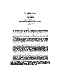
where h(root; θ) = h(root), leads to the ‘hat matrix’ diagonals, hii (θ). It is easy to show that 1 ≤ s(Tθ ) ≤ K for 0 ≤ θ ≤ 1. The fact that s(T0 ) = 1 and s(T1 ) = K is reassuring since the trees defined by these limiting values of θ consist of 1 and K different predictions respectively. Because of this behavior at the limiting values of θ, we are comfortable calling s(Tθ ) the ‘effective’ number of terminal nodes for arbitrary θ. One use of this measure is to mimic the display of prediction error as a function of tree size as defined by the error-complexity pruning sequence. For the data introduced in Section 1, the prototypic behavior for pruning and shrinking is displayed in Figure 5. The former is a step function due to the fact that there are a finite number of subtrees of T. The latter is a smoothly decreasing function of effective tree size. In this particular example we display the curve for two shrinking plans. The dashed curve corresponds to ‘naive’ shrinking (as described in Section 2) while the dotted curve corresponds to ‘optimal’ shrinking (as described in the next section). The fact that the former lies above the step function led us to consider more generalized shrinkage schemes. In the context of the relationship of 9
120.0
41.0
15.0
3.9
1500 500
1000
deviance
2000
2500
1400.0
2
4
6
8
10
size
Figure 5: Prediction error versus tree size (bottom axis) and complexity penalty (top axis) for the automobile mileage example. The curves are based on the resubstitution estimate, that is, prediction error is computed on the same data used to grow the tree. The step function defines prediction error for error-complexity pruning. The dashed curve defines prediction error for ‘naive’ shrinking. The dotted curve defines prediction error for ‘optimal’ shrinking. shrinking to pruning discussed in the previous section, the dominance of error-complexity pruning is due to the fact that the decrease from unit weights near the root occurs too fast for naive shrinking so that substantial bias is incurred. Similarly the decrease to near-zero weights deep in the tree occurs too slow so that excess variance is incurred. The ‘optimal’ shrinking scheme introduced in the next section attempts to ameliorate this behavior. In nearly all examples we have looked at to date, optimal shrinking (smoothly) follows the lower frontier of the error-complexity pruning curve. In general, prediction error is a decreasing function of actual or effective tree size when applied to the training set. For independent test data or cross-validation, prediction error is minimized, sometimes rather crudely, between the extremes of the full tree and the trivial (root node) tree. Figure 6 shows how imprecise the minimum is determined for this example. In particular, a maximal tree is indicated by both cost-complexity pruning and the two shrinking methods. This is hardly surprising in this case due to the strong smooth dependence of mpg on weight which successively larger trees are attempting to capture by a series of steps.
10
120.0
41.0
15.0
3.9
1500 500
1000
deviance
2000
2500
1400.0
2
4
6
8
10
size
Figure 6: Prediction error versus tree size and complexity penanlty for the automobile mileage example. The curves are based on 10-fold cross-validation, that is, prediction error is computed on data other than that used to grow the tree. The step function defines prediction error for error-complexity pruning. The dashed curve defines prediction error for ‘naive’ shrinking. The dotted curve defines prediction error for ‘optimal’ shrinking. The scales are the same as that of Figure 5.
5
Generalized Recursive Shrinking
The discussion so far has concentrated on a scalar shrinkage parameter θ which does not depend on the importance of the split, the fitted value in the node, the node size, et cetera. In this section we generalize the notion of recursive shrinking to allow shrinkage to depend on local node characteristics and yet still be parameterized by a scalar θ which globally controls the amount of shrinking. Thus certain local characteristics can be used to temper the amount of shrinking as the application dictates. We call one particular scheme “optimal shrinking” as it leads to node predictions that can be justified from determining the amount of shrinkage to minimize expected prediction error.
5.1
Node Functions
Let θl = f (node l; θ) denote a function of node l and a scalar (global) shrinkage parameter θ. It is convenient, but not necessary, to define θl such that f (node; 1) ≡ 1 and f (node; 0) ≡ 0, so that irrespective of local node characteristics, we obtain ‘no shrinking’ and ‘shrinking to 11
the root’ respectively. An example of a node function satisfying these requirements is θl =
(# in node) . (# in node) + (1/θ − 1)(# in sister)
Generalized recursive shrinking is defined by y (parent l; θp ) yˆ(node l; θl ) ≡ θl yˆ(node l) + (1 − θl )ˆ where θp = f(parent l; θ), the node function corresponding to the parent of node l. Predictions based on generalized recursive shrinking behave as those described in previous sections. In particular, predictions are convex combinations of the usual node predictions along the path from a leaf node to the root, yˆ(node; θ) ≡
d �
wj (θ)ˆ yj
j=0
where ⎧ d � ⎪ ⎪ ⎪ ⎪ (1 − θl ) ⎪ ⎪ ⎪ ⎨ l=1
wj (θ) =
for j=0
⎪ ⎪ d−j ⎪ � ⎪ ⎪ ⎪ θ (1 − θj+l ) ⎪ ⎩ d
for j > 0.
l=1
Similarly, tree sizing as described in Section 4 still obtains. We now describe a particular choice of the function f (node; θ) that enjoys some hueristic optimality justification as well as good performance in practice.
5.2
Optimal Shrinking of Regression Trees
Consider a simple tree consisting of a parent and two children nodes. Call the tree T, which results in predictions yˆ(x) = T (x), where T (x) = y¯L or y¯R depending on whether split(x)= LEFT or split(x)= RIGHT. Without loss of generality assume that x follows the left-hand branch. The question we address is whether it is possible to do better than yˆ = y¯L by considering node predictions of the form yL + (1 − θ)¯ y, yˆθ = θ¯ where y¯ = y¯ (parent). By ‘better’ we mean smaller expected prediction error, which for a new observation is given by P E(θ) = E(y − yˆθ )2 = E(y − θ¯ yL − (1 − θ)¯ y )2 . This is a quadratic function of θ minimized at θ∗ = 1 −
σ2 σ2 +
nL nR nL +nR (µL
12
− µR )2
where µL = E(y|LEF T ), nL = # in LEF T node, and similarly for the right node. The term σ 2 is the variance of y which is assumed constant across the tree. At optimal shrinkage, the PE is given by P E(θ∗ ) = σ 2
1+
1 nL
−
nR /nL nL nR ∆+nL +nR
where ∆ = (µL − µR )2 /σ 2 , the scaled difference between the children means. Optimal prediction error is an increasing function of ∆ with limiting cases P E(θ∗ ) =
⎧ 1 2 ⎪ ⎨ σ (1 + nL +nR ) if ∆=0 ⎪ ⎩ σ 2 (1 + 1 ) n L
if ∆ = ∞
Thus the optimal prediction error varies between the prediction error of the parent (∆ = 0) and that of the child (∆ = ∞). This optimum is attainable only if ∆ and σ 2 are known. In practice they are not known, and because Stein shrinkage only works for three or more means, replacing unknowns by estimates does not lead to an improvement over the unshrunken node averages. Our intention, however, is to shrink the entire set of terminal nodes toward the overall mean (i.e. the root node) in a recursive fashion. We therefore proceed to estimate the signal to noise ratio, for it will determine the relative amounts of shrinking in the overall shrinking scheme. The numerator and the denominator of the second term on the right hand side of θ∗ can be estimated by the within and between node mean squares respectively. The resulting estimated optimal shrinkage parameter is W θˆ∗ = 1 − B where �
(nL + nR − 2)W =
(y − y¯L )2 +
y∈LEF T
�
(y − y¯R )2
y∈RIGHT
and
B =
�
⎡
(y − y¯P )2 − ⎣
y∈P AREN T
=
�
y∈LEF T
(y − y¯L )2 +
�
⎤
(y − y¯R )2 ⎦
y∈RIGHT
nL nR (¯ yL − y¯R )2 . nL + nR
In the framework of generalized recursive shrinking, the basic idea is to apply this optimal estimate locally. Thus we consider node functions of the form θˆl∗ = f (node l; θ) where the information at node l consists of W l and B l . A useful way to interpret the local behavior of this shrinkage scheme relies on the fact that the significance level of the importance of splitl (x) is a one-to-one function of θˆl∗ . Thus, optimal shrinking allows one to weight a prediction according to the strength of the evidence that the split is meaningful. In 13
comparison, procedures which control tree growth use this test to either wholly accept or discard a candidate split. Error-complexity pruning on the other hand, uses the collection ¯l : l = 1, ..., K − 1} to determine it’s ‘optimal’ sequence of subtrees. {B As mentioned earlier, none of the shrunken nodes are really optimal. There are several reasons, the most basic being that the Stein result does not apply to individual node pairs. Also the optimal shrinkage estimator derived above assumes a fixed structure T , when in reality, T is the result of searching for that split(x) such that the between node mean ¯ and B, ¯ of the numerator and square is maximal. This implies that the estimates, W ∗ ˆ denominator of θ , are severely biased. For non-trivial trees things get worse rather than better as this maximization is performed at each node. In addition to this selection bias, ¯ l are also quite unstable across the tree, especially at the leaves the individual estimates W of particularly large trees where pure nodes are not uncommon. For all these reasons we introduce an additional regulating parameter θ to modify the “optimal” values of θˆ∗ , while still maintaining the spirit of the optimality result. The particular ‘optimal’ shrinkage function we propose is given by �
θˆl∗
= f (node l; θ) =
1 − ( 1θ − 1) × 0
¯0 W ¯l B
¯0 ≤ B ¯l f or ( 1θ − 1)W otherwise
where W 0 = s2 , the root node mean square. The purpose of replacing W l by W 0 is to trade local adaptation (by W l ) for global stability (of W 0 ). The scalar multiple ( 1θ − 1) is introduced to adapt to the selection bias. This peculiar choice of scaling is used so that θ → 1 forces θˆl∗ → 1, while θ → 0 drives θˆl∗ → 0 regardless of local node characteristics. Despite these modifications, we still call this scheme ‘optimal’ local shrinkage, if only because we have yet to find a generalized recursive shrinkage scheme which demonstrates better performance.
5.3
Class Probability Trees
The derivation in the previous section concerned regression trees and squared prediction error. This leads to the optimal scheme being a function of (¯ yL − y¯R )2 , or equivalently, a function of the between node sum of squares. By analogy, but without formal justification, we generalize this scheme to class probability trees by replacing squared error by the multinomial deviance dev(node) = −2loglik(p; node) = −2
J � �
yij logpij ,
i∈node j=1
where yij = 1 if observation i is in class j and yij = 0 otherwise. This results in the optimal shrinkage scheme defined by the between node deviance B l = dev(parent l) − [dev(node l) + dev(sister l)] and the (global) within node deviance W0 =
dev(root) . N −1 14
For readers unfamiliar with the term ‘deviance’, B l is simply the likelihood ratio statistic associated with the hypothesis test that splitl is unnecessary. The example described in the next section uses this definition, with apparent success, although extensive examination of alternatives has not been undertaken.
6
The Faulty LED Example
A small but useful example of class probability trees is that based on recognizing the digit output by an LED device (Breiman et al, 1984). Such devices display the digits 0—9 by activating combinations of seven line segments which define the top, upper left, upper right, middle, lower left, lower right, and bottom sides of a rectangle split in two. A faulty LED display is considered whereby each line segment can have its parity changed with a fixed probability, independently of the others. In the example discussed below this probability is 0.10. Given a sample of faulty LED digit data, the challenge is to construct a class probability tree for prediction of future digits. We use a sample {y, x1 , . . . , x7 } of size N=200 for tree construction, where y denotes the target digit and xj the parity of the jth segment. We use the deviance measure for node heterogeneity and halt tree growth only when the node is pure or the node size is less than 10. The resulting tree is displayed in Figure 7. Nodes are labeled by their modal category (i.e. the most numerous digit in the node). Optimal shrinking was applied to this tree at 10 prespecified values of α in the unit interval, (1/20, 2/19,. . . , 10/11), resulting in tree sizes ranging from 1.8 to 33 effective terminal nodes. Figure 8 displays the dependence of prediction error for the optimal shrinking scheme as a function of effective tree size. The monotone decreasing curve is the resubstitution estimate of prediction error; the upward arrows point to that obtained from 10-fold cross-validation on these data; the solid curve is based on an independent test sample of size 200. The latter two point fairly sharply to a shrunken tree with approximately 10 effective terminal nodes. This in turn corresponds to α = 5/16. A comparison of shrinking with error-complexity pruning is hampered by the fact that the latter ‘explodes’ when a node predicts the observed digit to have probability zero (recall that the deviance is a sum of terms of the form logpij ). Shrinking is immune to this problem since the shrunken prediction at each node borrows from the root, which only in extremely pathological cases will not have particular classes represented. One measure which can be computed for both methods is the misclassification error rate. Breiman et al (1984) obtain a misclassification error rate of cost-complexity pruning of 0.30. (Cost-complexity means that the pruning was done using this measure as opposed to error deviance.) The misclassification error rate of the optimally shrunken tree is also 0.30. Both of these are obtained on independent test samples.
7
Related Methods
There is little existing treatment of shrinkage for trees, save one reference, which we discuss below. An abundance of material has appeared on shrinkage in other more common models. We superficially discuss the apparent connection between our method and this material,
15
| 4
2
4
2
2
7
2
4
7
0
1
1
7
1
7
0
7
4
3
3
0
4
5
4
3
0
4
7
5
4
5
0
0
0
6
0
0
9
6
0
0
4
4
0
8
2
6
2
8
Figure 7: The tree grown to the faulty LED data prior to simplification or shrinkage. The numbers under each node correspond to the modal category for each node. Thus for these data, the digit “4” is the most numerous. The left side of the tree is attempting to sort out differences between the digits “2” and “7” and then “1” and “7” and then “0” and “3”. The right side is attempting to sort out differences between the digits “4” “5” and then ‘5” “9” and “0” and then “0” “6” and “4” and finally “2” “8” and “6”. which we hope will encourage others to pursue in more detail.
7.1
Shrinking classification trees
Bahl, Brown, de Souza, and Mercer (1987) introduce shrinking in their application of classification trees in natural language speech recognition. Their primary motivation is to smooth class probabilities based on sparse data; the particular application involved modeling a 5000-nomial! They assign a separate vector θk to each leaf node, where the elements of θk weight cell proportions along the path from the leaf to the root. They determine the entire set Θ by minimizing prediction error (deviance) in an independent test set. The similarity with our approach is that they condition on the topology of the fitted tree in their optimization over the shrinkage parameters. The difference is the dimensionality of the parameter space, ours having a single adjustable parameter and a user-defined function 16
1000 800 600
prediction error
o
400
o o o
200
o
5
10
o
o
o
15
20
o
25
o 30
size
Figure 8: Prediction error (deviance) versus tree size for the faulty LED tree. All points and curves are for ‘optimal’ shrinking. The asterisks are based on the resubstitution estimate. The arrowheads are based on 10-fold cross-validation. The solid curve is based on an independent test sample of size 200. f (node; θ), while theirs is wholly unconstrained, except that for each leaf the θ’s along the path to the root are required to sum to one. We have made no formal comparison of the two approaches.
7.2
Non-Recursive Shrinkage Methods
An alternative class of shrinkage estimates for trees is nonrecursive, and based on a linear model representation of a binary tree. Specifically consider a set of basis vectors for a fixed tree T which corresponds to the sequence of splits defined by T, one basis vector for each split and one for the root node. The root is the “grand mean” and is represented by a column of 1’s. The remaining columns can be defined in a variety of ways. We choose a representation that coincides with the “effects” defined in Section 3, namely that at each split, the effect is e = yˆ(lef t child) − yˆ(parent). If the first split sends nL observations to the left, and nR to the right, then it is easy to show that the appropriate contrast vector for this first “effect” has nL elements equal to 1, the remaining nR elements equal to −nL /nR . This contrast is orthogonal to the root contrast (i.e. the column of ones). This pattern is repeated for further splits, with zeros in the contrast vector for observations not in the node being split. The resulting basis, say A, 17
has dimension N × K where K is the number of terminal nodes. The vector of “effects,” e = (A� A)−1 A� y, is that defined in Section 3, where each effect has an associated depth. Fitted values are obtained as linear combinations of these effects, namely yˆ = Ae. We now consider shrinking the effects. As a further simplification, we can assume that A is orthonormal. Then yˆ = AA� y and H = AA� is the operator (projection) matrix for the tree. By analogy with Section 3, we must shrink effects at depth q using weights Wq = 1 − (1 − θ)d−q where d is the maximum depth of the tree. If D(θ) is the K × K diagonal matrix of these effect weights, then H(θ) = AD(θ)A� is the shrunken operator matrix. An alternative form is: H(θ) = A(I + D(θ)−1 − I)−1 A� = A(A� A + P (θ))−1 A� where P (θ) is the diagonal “penalty” matrix with elements corresponding to depth q having value pq = W1q − 1. Since W0 = 1, the root effect is not penalized, but successively deeper effects receive a higher penalty. Notice that this shrinkage scheme is not the same as recursive shrinking which has the property that an effect which is shared by terminal nodes of different depths receives different weights. The resulting shrunken estimator solves the penalized least squares problem min || y − Ae ||2 + e� P (θ)e, e
and has a flavor very similar to smoothing splines. This analogy with more traditional shrinkage and smoothing methods is alluring, and encourages one to “design” other shrinkage schemes. The ingredients for such a construction are: • a basis A representing the full tree; preferably the elements of the basis should be orthonormal vectors with an obvious ordering; in our example above the basis vectors are ordered by depth. • a shrinking scheme D(θ) for weighting the effects. We resist the temptation to pursue these ideas but expect that the presentation here will facilitate the future development of such methods.
8
Computing
It is an interesting historical note that the idea of shrinking trees initially arose in an effort to implement tree-based models in a widely used and extendible computing environment (S— Becker, Chambers, and Wilks, 1988). Specifically, that implementation (Becker, Clark and Pregibon, 1989) was based on the ideas in Breiman et al. (1984) as seen through a software developer’s eyes: separate out the logical and distinct steps in fitting tree-based models into distinct software modules. The initial modules consisted of functions for growing, pruning and cross-validating trees and five functions for displaying trees. These were followed by 18
a host of functions for interacting graphically with trees, such as snipping off branches, selecting subtrees, identifying which observations fall where, et cetera. The idea was to exploit the graphical representation of the model as a binary tree in the analysis of the data, and not merely for presentation purposes. Subsequent functions included those for prediction, auto-coding of C language prediction subroutines, editing splits, and interactive tree growing whereby the user can temper the optimization performed at each node with contextual information to alter the usual tree growth. The key notion that ties the functions together is the tree data structure, which in the current implementation, consists of a matrix summarizing the results of the recursive partitioning algorithm, and an (optional) list of which terminal node each observation falls into. This object can be plotted and manipulated by other functions, most of which produce either a side-effect (e.g. some tree display) or a new tree structure (e.g. the result of snipping branches off a tree). The software implementation thus supports the notion that one grows an overly large tree and assigns the result to a tree object. The tree can be simplified by applying errorcomplexity pruning. But so long as we have the overly large tree, why not entertain other methods of simplification or enhancement for prediction? And thus the germ of the idea, ”What else can one do?” was born and subsequently addressed by relating it to ideas more commonly applied to linear parametric models, namely shrinkage. The computations are carried out by determining the generalized shrinkage parameters θl for each node in the tree, and then applying these to the nodal predictions layer by layer, starting from the root and proceeding to the maximal tree depth. This procedure thereby provides shrunken predictions throughout the tree, not just at the leafs. Once deviances are computed at each node, the information is organized into a tree data structure, thereby allowing plotting, prediction, cross-validation, or further manipulation. We note finally that there is no inherent restriction that shrinking be applied to an entire tree. Indeed it might often be the case that certain subtrees are singled out for differential treatment. Thus, one portion of the tree can be shrunken at a certain value, θ, another at a different value, θ� , and yet another can be simply pruned or left alone entirely. Any implementation of tree-based methods should encourage such improvisation.
9
Acknowledgements
The ideas in this paper were first presented at the 2nd International Conference on AI & Statistics in January 1989. Since then they have benefited by numerous discussions with colleagues at Bell Laboratories. In particular we acknowledge the insightful comments of Colin Mallows, who in fact, derived the optimal local shrinking parameter θ∗ and it’s estimator θˆ∗ discussed in Section 5.
10
References
[1] Lalit R Bahl, Peter F Brown, Peter V de Souza, and Robert L Mercer (1987), “A Tree-Based Statistical Language Model for Natural Language Speech Recognition,” Computer Science Tech Report #58679, Watson Research Center, IBM.
19
[2] Richard A. Becker, John M. Chambers, and Allan R. Wilks (1988), “The New S Language,” Wadsworth & Brooks/Cole Advanced Books and Software, Pacific Grove, California. [3] Marilyn Becker, Linda A. Clark, and Daryl Pregibon (1989), “Tree-based models in (new) S,” Proc. Stat. Comp. Sec., Annual ASA Meeting, Washington DC. [4] Leo Breiman, Jerome H. Friedman, Richard A. Olshen, and Charles J. Stone (1984), “Classification and Regression Trees,” Wadsworth International Group, Belmont, California. [5] Philip A. Chou, Tom Lookabaugh, and Robert M. Gray (1989), “Optimal Pruning with Applications to Tree-Structured Source Coding and Modeling,” IEEE Trans. Inf. Theory 35, p299-315.
20
11
Appendix: H (θ) for Simple Recursive Shrinking
Let X be the N × K matrix of dummy variables that represent the set of terminal nodes. Suppose that the columns of X are ordered by the depth of the corresponding terminal node, and denote the number of observations at leaf node l by nl . Now H = X(X � X)−1 X � where X � X = diag (n1 , n2 , . . . , nK ). The vector of fitted values for the K terminal nodes is y¯ = (X � X)−1 X � y, and premultiplication by X expands them out to fitted values, yˆ = X y¯ = Hy, for the N observations. The operator matrix for a recursively shrunken tree can be expressed as H(θ) = XΘ(X � X)−1 X � . The size of the tree is defined as s(Tθ ) = traceH(θ) = traceΘ. The matrix Θ is a full K × K matrix since every shrunken terminal node depends on all the other nodes. For a simple 3 terminal node example with the first terminal node at depth one and the other two at depth two, Θ = {Θi,j : i, j = 1, 2, 3} has individual elements: ⎡ ⎢ ⎢ ⎢ ⎢ ⎢ ⎢ ⎢ ⎣
θ+
(1−θ)n1 n1 +n2 +n3
(1−θ)2 n1 n1 +n2 +n3 (1−θ)2 n1 n1 +n2 +n3
(1−θ)n2 n1 +n2 +n3
θ+
θ(1−θ)n2 n2 +n3
θ(1−θ)n2 n2 +n3
+
+
(1−θ)2 n2 n1 +n2 +n3
(1−θ)2 n3 n1 +n2 +n3
(1−θ)n3 n1 +n2 +n3 θ(1−θ)n3 n2 +n3
θ+
+
θ(1−θ)n3 n2 +n3
(1−θ)2 n2 n1 +n2 +n3
+
(1−θ)2 n3 n1 +n2 +n3
⎤ ⎥ ⎥ ⎥ ⎥ ⎥ ⎥ ⎥ ⎦
¯ � where Θ ¯ = Θ(X� X)−1 . The Further insight can be gained by expressing H(θ) = XΘX ¯ are obtained by dividing the jth column of Θ by nj . For our simple individual elements of Θ three terminal node example one obtains 2 ¯ 2,2 = θ + θ(1 − θ) + (1 − θ) . Θ n2 n2 + n3 n1 + n2 + n3
Since X represents the set of basis vectors for the K terminal nodes, pre- and post¯ by X yields multiplication of Θ ¯ k,k hii (θ) = Θ where the subscripts convey the fact that the ith observation falls into the kth terminal node. Thus the diagonal elements of H(θ) are defined by the usual recursion applied to 1 as described in Section 4. # in node
21