nal processing algorithms on a recon gurable paral- lel architecture. ... allel processor where each processing element is ... this purpose, the system provides a C-language in- terface and ..... volution algorithm on Splash 2 to be used on digital.
Signal Processing Applications using VHDL on Splash 2 Sea H. Choi, Nalini K. Ratha, Moon J. Chung, and Diane T. Rovery Dept. of Computer Science Michigan State University East Lansing, MI 48824 y Dept. of Electrical Engineering
Abstract This paper reports the use of VHDL in modeling signal processing algorithms on a recon gurable parallel architecture. The algorithms are speci ed by describing the behavior of each processing element of the parallel system and then synthesized for the speci c hardware. The advantages and limitations of using VHDL in such an environment are reported.
1 Introduction Signal processing applications are computation intensive primarily because of the large amount of data to be handled in a very short time. Using single processor machines, we cannot get the desired performance. Parallel machines and application speci c integrated circuits (ASICs) are used to obtain the desired speed. However, these options are costly. Furthermore, once the ASIC is built, it is very di�cult to change the design. Field Programmable Gate Arrays (FPGAs) have gained considerable attention recently because of their recon gurability. FPGAs allow a new form of computing where the architecture of a computer may evolve over time, changing to t the needs of each application it executes. With an FPGA-based machine, the architecture can be tailored to meet the desired performance for the given application. The recon gurable architecture we have adopted is Splash 2, developed and built by Supercomputing Research Center (SRC). Splash 2 is a special purpose attached parallel processor having processing elements (PEs) based on user programmable Xilinx 4010 FPGA chips. The Splash 2 system consists of a Sun SPARCstation as a host, an interface board,
and Splash array boards ranging from one to sixteen boards. Each array board of Splash consists of 16 PEs having linear connections as well as a recon gurable crossbar interconnection between PEs. VHDL is used to model the computational algorithms as well as the architectures. Simulation is used to verify the parallel model. Then, from the VHDL description, the compiler re-targets the algorithms and architecture into FPGAs. Thus, the role of VHDL in this system is multifaceted: it is used as both the speci cation (modeling) language and the implementation language. It describes algorithms within user applications and the necessary hardware to realize them (including processing units, memories, and interconnections). To support our current work in image processing and to test the use of Splash 2 and VHDL on a widely used algorithm, we have implemented 1-D and 2-D convolution algorithms. This paper is organized as follows. The Splash 2 architecture is introduced in the next section including the programming environment of the system. Section 3 covers the basic theory of convolution and the algorithm used. The VHDL implementation is covered in section 4. Experimental results are presented in section 5. Conclusions are given in section 6.
2 Splash 2 Splash 2 [1] is an attached special purpose parallel processor where each processing element is a user programmable FPGA chip. The architecture of Splash 2 can easily support parallel applications, such as systolic or data-parallel computations. Splash 2 is developed/modi ed from the
Splash 1 system [2] which consisted of a xed size linear array of Xilinx 3090 FPGA chips. Splash 2 has several improvements over Splash 1. Splash 2 is based on newer hardware technology, the Xilinx XC4010 FPGA. A crossbar is added to connect PEs on a board in any pattern. The linear path was the only con guration in Splash 1. The programming environment centers on VHDL in place of SRC's Logic Description Generator (LDG) [3, 4, 5].
2.1 Splash 2 Architecture
Crossbar
Interface Board XL
X1 X2 X3 X4 X5 X6 X7 X8
SIMD Bus X0
XR
Crossbar
RBus X16 X15 X14 X13 X12 X11 X10 X9
X1 X2 X3 X4 X5 X6 X7 X8
X0
WR
SBus Address
RD WR
Address
Data
32
16
18 SBus Data
32
Processor Inhibit
Processing Element (PE) To Right
To Left Neighbor
Neighbor 36
To Crossbar
X16 X15 X14 X13 X12 X11 X10 X9
Input DMA SBus Extension Output DMA
SBus Write
256k By 16 Memory
36
X1 X2 X3 X4 X5 X6 X7 X8
Sparc Station Host
RD
36
Splash Boards
X0
SBus Read
Crossbar X16 X15 X14 X13 X12 X11 X10 X9
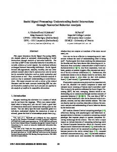
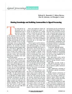
Figure 1: Splash 2 Architecture The Splash 2 is attached to a Sun SPARCstation host. Figure 1 shows the Splash 2 architecture [6, 7]. The host is connected to the Splash 2 via an interface board. The host can read/write to memories on the Splash processing boards via this interface board. Each Splash 2 processing board has 16 processing elements, X1 through X16, and there is one special PE, X0 , which controls the data ow into the processor board. Each Xi is a PE built around a Xilinx 4010 FPGA chip. A crossbar connection can be programmed by X0 . The processing element organization is shown in Figure 2. Each PE has 512 KB of attached memory, which has a 16-bit word size. The host can also read/write this memory over the SBus. Each PE can communicate using the SIMD Bus
Figure 2: A Processing Element (PE) in Splash 2 (left-right neighbor data paths) or the crossbar. Data can be broadcast using the crossbar. The Splash 2 architecture supports systolic and pipeline modes of computation, SIMD or data-parallel mode (PEs execute the same instructions on di�erent data streams), or even MIMD mode (PEs execute different instructions on di�erent data streams). The Splash 2 system can run at a maximum clock speed of 40 MHz where the maximum is limited by the FPGA technology. The actual operating speed is determined when the FPGA logic is synthesized.
2.2 Programming Splash 2 The programming environment for Splash 2 is based on VHDL [8, 9]. The behavioral description is analyzed, simulated, and synthesized onto Xilinx FPGAs. An application for Splash 2 is developed by writing its behavioral description in VHDL, and the description is iteratively re ned and debugged with the Splash 2 system simulator. After the description is veri ed to be functionally correct by simulation, it is translated into a Xilinx net list form. The net list is then mapped onto the FPGA architecture by an automatic partition, placement and routing tool to form a loadable FPGA object module. A static timing analysis tool is then applied to the object module to determine the maximum operating speed. This process is shown in Figure 3. To program Splash 2, we need to program each of the PEs, i.e. X0 through X16 , and the host interface. The host interface is responsible for data transfers between host and the Splash 2 board. For this purpose, the system provides a C-language interface and C programs are written for the host's tasks.
1. 2. 3.
Input:
A 1-dimensional vector f(t), a mask vector g(t). A 1-dimensional result vector h(t). Assume k PEs are available. The ith PE holds the g(i) mask value.
Output: Begin
On each PE:
Receive from left neighbor: signal value f(i), partial sum S(i-1). Compute new partial sum S(i) = S(i-1) + f(i) * g(i). Send signal value f(i) and partial sum S(i) to right neighbor.
End.
VHDL Source
Simulation
Logic Synthesis
Partition, Place and Route Timing of Logic
Splash 2
Figure 3: Splash 2 Programming Flow Diagram
3 Convolution An important class of signal and image processing algorithms are based on the convolution of two signals. For analog one-dimensional signals, f (t) and g(t), their convolution h(t) is de ned as
Z +1 g(x)f (x ? t)dx h(t) = ?1
(1)
For discrete-time one-dimensional signals, this reduces to the following equation:
h(t) =
X g(x)f (x ? t) +1
?1
(2)
Further, if the signal g(t) is a nite-time-duration signal (called the mask signal), then the summation range changes, so that
h(t) =
X+ g(x)f (x ? t) k
x=1
(3)
where k is the mask size. On a sequential machine, convolution is easily implemented. However, a sequential computer may
not be practical when convolution needs to be done in real-time for a large number of data points. For parallelizing a convolution computation, two approaches can be taken [10]: (i) data parallel computing and (ii) systolic computing. Data parallel computing uses a divide-and-conquer approach to deal with the large amount of data. Usually f (t) has large number of data points (spread over a large time domain) compared to the mask signal g(t). Hence, a set of processors can be used to compute on shorter segments of the data in parallel. This computational model assumes that each PE is powerful enough to carry out all computations and that signal values are already available at each PE. If this latter assumption is not the case, then the data path from host to PEs becomes a bottleneck in distributing data to the PEs. This problem can be overcome using a systolic approach. This requires only a single data path between the host and k PEs and that the PEs are powerful enough to perform the add and multiply operations. A set of PEs are used as a linear array. The basic convolution algorithm translates into the above systolic algorithm. The input is fed into the PE array at the left input of the rst PE with the partial sum initialized to zero. At the output of the last PE, the nal result is obtained. It can be readily seen that the algorithm, after the initial pipeline latency, will output one result every clock cycle. The overall model has been schematically described in Figure 4. If the number of PEs available is smaller than the number of mask values, we need to map virtual PEs to the physical PEs using a fair policy. In that case, the PEs need wider communication paths and will require more cycles to produce results.
PE left_in sum_left
Memory
right_out
right_out =0) THEN sum := mask * left_in + psum; ELSE sum := psum2; END IF; right_out