solidi
status
physica
pss
Phys. Status Solidi C, 1– 10 (2016) / DOI 10.1002/pssc.201600220
c
www.pss-c.com
current topics in solid state physics
Similarities and differences between two different types of the thermoluminescence dosimeters belonging to the LiF family A. M. Sadek*,1, F. Khamis2, George S. Polymeris3, E. Carinou4, and G. Kitis5 1
Ionizing Radiation Metrology Department, National Institute for Standards, El-Haram, Giza, Egypt Physics Department, University of Tripoli, Tripoli, Libya 3 Institute of Nuclear Science, Ankara University, Besevler, 06100 Ankara, Turkey 4 Greek Atomic Energy Commission (GAEC), PO Box 60092,15310 Ag. Paraskevi, Greece 5 Nuclear Physics and Elementary Particles Physics Section, Physics Department, Aristotle University of Thessaloniki, 54124 Thessaloniki, Makedonia, Greece 2
Received 15 September 2016, revised 21 October 2016, accepted 10 November 2016 Published online 25 November 2016 Keywords thermoluminescence, glow curve analysis, LiF, dosimeters *
Corresponding author: e-mail
[email protected], Phone: +20 1114077224
The kinetic parameters of the glow-peaks of Harshaw - LiF : Mg, Ti (TLD) and Poland - LiF : Mg,Ti (MTS) dosimeters were investigated at different dose levels using the computerized glow-curve deconvolution (CGCD) algorithm. The results showed that the glow-curve structure and the kinetic parameters of the MTS - 6 and the TLD dosimeter are identical. In addition, the glow-curve structure and the kinetic parameters of the MTS - N and MTS - 7 dosimeters. However, unusual low activation energy ( ~ 1.67 eV ) and frequency factor ( ~ 1015 s -1 ) values were detected for peak 5 of MTS - N, and MTS - 7 at the 50 Gy
dose-level. Moreover, unlike the activation energy and the frequency factor of peak 5 of the TLD dosimeters, the activation energy and the frequency factor of peak 5 of MTS - N and MTS - 7 are substantially dependent on the absorbed dose level. The results also showed that peak 2 of the same dosimeters has also unusual low activation energy and frequency factor values. However, these values showed high stability over the different dose levels. The explanations of these unusual behaviors of peak 5 were discussed and a correlation between peak 2 and peak 5 was pointed out.
© 2016 WILEY-VCH Verlag GmbH & Co. KGaA, Weinheim
1 Introduction Harshaw - LiF : Mg, Ti (will be referred to as TLD) has been found to be the most popular and useful among the thermoluminescence (TL) materials for use in radiation dosimetry. Daniels et al. [1] were the first to investigate the LiF reagent, but it was first used as a commercial TLD by Cameron et al. [2] and named TLD100 with two isotopic components of 6 Li ( 7.4%) and 7 Li ( 92.6% ). Later, two more LiF - TLD isotope phosphors namely TLD-600 (95.62% 6 Li and 4.38% 7 Li ) and TLD700 ( 0.007% of 6 Li and 99.993 of 7 Li ) were also produced. The TLD dosimeters are doped with magnesium (approximately 300 ppm ) as the main dopant, and the titanium (approximately 11.5 ppm ) as the activator [3].
Due to its importance in dosimetric applications, the main dosimetric peak 5 in TLD is probably the most intensely studied peak in the history of thermoluminescence [4]. Under the usual thermal conditions, high values of activation energy ( 2.0 eV < E < 2.3 eV ) and the frequency factor (1019 s -1 < s < 1023 s -1 ) were reported for this peak [5-10]. However, low values of E and s were also reported for this peak. These low values were, probably, due to the application of unusual thermal conditions, e.g. performing the reading out using a very high heating rate [11], or slow cooling following the annealing at 400 ∞C [12]. Other research groups, using the peak shape analysis, have also reported low E and s values, but these do not refer © 2016 WILEY-VCH Verlag GmbH & Co. KGaA, Weinheim
2
solidi
status
physica
pss
c
A. M. Sadek et al.: Similarities and differences between two different types of TL dosimeters
to TLD but to other types such as LiF : Mg [13], LiF : Mg, Ti with 277 ppm Mg and 13.5 ppm Ti [14]. In general, the high E and s values describe an abnormally narrow shape for the glow-peak. The low E and s values arise from a much broader distribution. The high-temperature TL (HTTL) appearing in the glow-curves of TLD is usually taken to refer to the TL which appears at temperature above the main dosimeteric peak. The maximum intensity of HTTL is commonly referred to as peak 7 [15]. Two additional peaks between peak 5 and peak 7 were observed under certain circumstances. These peaks were referred as peaks 5a and 6. Peak 5a was originally introduced by Fairchild et al. [33]. Kitis and Otto [36] concluded that this peak cannot seen in the usual glow-curve, resulting after the normal annealing. This peak appears at low annealing temperature of 140 o C and 160 o C . On the other hand, the sintered Poland - LiF : Mg, Ti (will be referred to as MTS) dosimeters are being commercially produced at the Institute of Nuclear Physics (INP) in Krakow under the trade name MTS - N ( N stands for natural 6 Li / 7 Li abundance) and consist of lithium ( 26.70% ), fluoride ( 73.28% ) [16]. The MTS dosimeters are also doped with magnesium ( 120 ppm ), and titanium ( 13 ppm ) [17]. These dosimeters are being utilized for all practical applications equivalent to the TLD s [18]. They have been used in the routine dosimetry measurements of dose levels 5 - 50 mGy [19, 20], in the measurements of high gamma radiation of 1200 kGy dose level [21], in long-term environment monitoring [22]. It has been also used extensively in the measurements of the cosmic radiation and ion beams [23]. In these applications, the ratio of the high-temperature peaks to the main dosimetric peak 5 makes the high-temperature glow peaks to be of great importance. Furthermore, the kinetic parameters of this dosimeter have not attracted the sufficient attention probably because the results of huge literature existing for TLDs are extrapolated to MTS. The aims of the present work are: (i) Investigate the kinetic parameters of the glow-peaks of MTS dosimeters, to compare them with those of TLDs and to examine the degree that TLD literatures results can be extrapolated to MTS dosimeters. (ii) Investigate features of the low-temperature preirradiation annealing. (iii) Investigate possible effect of the absorbed dose level on the kinetic parameters of both types of dosimeters. (iv) Investigate and compare in details the properties of the high-temperature peaks. 2 Experimental procedure 2.1 Sample details The samples used in the present work were five samples of each type of the TLD of Harshaw (with dimensions of (3.2 ¥ 3.2 ¥ 0.89 mm3 ) and 5 samples of each type of MTS produced at the Institute of Nuclear Physics (INP) in Krakow (with diameter of 4.5 mm and thickness of 0.8 mm ). © 2016 WILEY-VCH Verlag GmbH & Co. KGaA, Weinheim
2.2 Annealing and irradiation conditions The dosimeters were annealed using the standard conditions, i.e. 400 °C for one hour followed by two hours at 100 °C . Then, the dosimeters were irradiated with different doses using a 90 Sr - 90 Y source. Sadek et al. [24] investigated the influence of changing the absorbed dose-level on the kinetic parameters using a model of one active trap, one recombination center and one thermally disconnected deep trap (competitor). They concluded that the value of the activation energy of the active trap may change as competitor approaches the dose-saturation level. In this case, the rate of the accumulated electrons in the active trap changes, e.g. from linear to supra-linear. Therefore, in the current work, the samples were irradiated to different dose levels in order to investigate the kinetic parameters in case of linear and supra-linear dose response regions. The first dose level was 0.5 Gy which is corresponding to the linear dose region [4, 17]. The other two dose-levels (i.e. 8 Gy and 50 Gy) are corresponding to the supra-linear region. 2.3 Apparatus and measurement conditions The measurements were carried out using a Riso TL/OSL reader (model TL/OSL-DA-15), equipped with a 90Sr/90Y beta source, delivering a nominal does rate of 0.105 Gy/s. A 9635QA photomultiplier tube with a combination of Pilkington HA-3 heat absorbing and Corning 7-59 (320440 nm) blue filter were used for light detection. All measurements were performed in a nitrogen atmosphere with low constant heating rate of 1 o C / s , in order to avoid significant temperature lag, and the samples were heated up to the maximum temperature of 350 ∞C. 3 Method of analysis The method of computerized glow curve deconvolution (CGCD) analysis will be used to investigate the aims of the present work set in the introduction. The values of the kinetic parameters for the low-temperature peaks (2-5) of LiF : Mg, Ti are very well known with a very high reproducibility in TL literatures. On the other hand, the kinetic parameter values of the high-temperature peaks are also known, although, with less accuracy. Another detail of the analysis in present work that it will performed using TL single peak analytical expressions, recently derived by the solution of the system of differential equations of the most elementary TL model, the one trap-one recombination center (OTOR) model. Furthermore, since there is no accumulated experience with the recent analytical expressions, the CGCD analysis will be also performed using the conventional empirical generalorder kinetics equation. The new expressions were originally deduced by Kitis and Vlachos [25] to fit the glow-peaks generated with R < 1 and R > 1 , where R = An / Am is the trappingrecombination coefficients ratio. The accuracy of these equations in calculating the activation energy was verified for the glow-peaks simulated by different TL models [24, 26, 27]. The main conclusion was that these equations are www.pss-c.com
Contributed Article Phys. Status Solidi C (2016)
3
superior to the general-order kinetics (GOK) and the mixed-order kinetics (MOK) equations in the determination of the activation energy. Moreover, unlike the GOK equation which is entirely empirical, these equations are based on the physical OTOR model. Later, these equations were developed by Sadek et al. [10] in order to be employed in the deconvolution process of experimental glowcurves. These equations were utilized in the deconvolution analysis of different complex glow-curves including the both the TLD and MTS glow-curves. Sadek et al. [10] concluded that all the glow-peaks of both dosimeter types could be fitted with the equation corresponding to R < 1 . In its final form and for linear heating rate, it is given by [10]
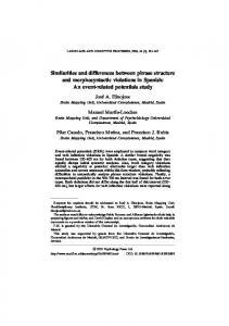
4 Experimental results 4.1 Preliminary glow-curve structure comparison under usual treatments The glow-curves of both TLD-100 and MTS dosimeters normalized to the peak maximum I m and peak maximum position Tm of peak 5 are shown in Fig. 1. The glow-curves of TLD-600 and TLD-700 dosimeters were not represented in the figure because they are identical with the glow-curve of TLD-100.
W [exp ( Z m )] + W [exp ( Z m )] Ê E Ê 1 1 ˆˆ exp Á - Á - ˜ ˜ , 2 Ë k Ë T Tm ¯ ¯ W [exp ( Z )] + W [exp ( Z )] 2
I = Im
(1) where I is the TL intensity, I m is the maximum intensity, Tm is the position of the maximum intensity, E is the activation energy, k is the Boltzmann constant, W is Lambert-w function and Z m = Z (at T = Tm ), where Ê E ˆ E exp Á Ë kTm ˜¯ 1 Z = - ln (c ) + F (T , E ) , c k Tm2 FTL1 (1 - R )
(2)
FTL1
-1.05 R1.26 + 1 , = (1 - R )
(3)
c=
no R . N (1 - R )
(4)
Sadek et al. [26] concluded that changing the no / N did not affect on the value of the computed E as long as R < 1 . Thus, it is suitable to set no = N so that the final equation will be a function of only four unknown parameters. The frequency factor was calculated using the peak maximum condition given by [25]
bE Ê E ˆ = FTL s exp Á , Ë kTm ¯˜ kTm2
(5)
where b is the linear heating rate. The goodness of the fit was measured by the figure of merit (FOM) given by [28] jf
yi - y ( xi ) ¥ 100 , A
Figure 1 The glow-curve of the TLD-100 and MTSPoland dosimeters irradiated at 50 Gy in a 90Sr - 90 Y beta source. The glow-curves were normalized to the peak maximum ( I m ) and peak maximum position ( Tm ) of peak 5.
It is obvious that the glow-curves can be divided into two regions. The first region includes the low-temperature glow-peaks ( 300 - ~ 500 K), i.e. the 1 - 5 glow-peaks. In this region, the glow-curve structures of both TLD - 100 and MTS dosimeters are approximately identical. However, larger area of peak 4 of MTS - N glow-curves has been observed. The second region (>~ 520 K) , includes the high-temperature glow-peaks. It is clear that the structure of these glow-peaks in the two types is completely different. This observation has been also referred to by Olko et al. [17]. In the glow-curves of TLD dosimeters, the high-temperature glow-peaks consist of three overlapped glow-peaks including peak 5a. While, in MTS - N, and -7 , the high-temperature glow-peaks seem to be consisting of at least three overlapped glow-peaks without including peak 5a. However, the glow-curve structure of MTS - 6 is approximately identical with the glow-curve structure of TLDs .
4.2 The glow-curve analysis under usual thermal treatments The TL properties of the TLDs , in genji eral, are notoriously variable and non-universal [29-32]. where FOM is the figure of merit, ji is the first channel This, in fact, is caused by the complexity of their glowin the region of interest, j f is the last channel in the re- curves. The shape of main dosimetric peak 5 is affected by gion of interest, yi is the information content of channel j , the two peaks, which are commonly labeled peaks 4 and 5a. y ( xi ) is the value of the fitting function in channel j , and Unfortunately, these two peaks closely straddle peak 5, A is the integral of the fitted glow-peak in the region of rendering a neat study of peak 5 rather difficult. The relative intensities of peaks 4 and 6 following g irradiation interest. are typically of the order of 35% and 2% respectively, of FOM (% ) = Â
www.pss-c.com
(6)
© 2016 WILEY-VCH Verlag GmbH & Co. KGaA, Weinheim
4
solidi
status
physica
pss
c
A. M. Sadek et al.: Similarities and differences between two different types of TL dosimeters
peak 5 intensity [8]. Thereby, at low dose levels and under the usual annealing procedures, the interference from peak 4 accounts the greater problem. On the other hand, the existence of peak 5a was originally introduced by Fairchild et al. [33], as a requirement to obtain a good fit to the experimental glow-curve of TLD . However, Gartia and Sing [34] and Abd El-Hafez et al. [3] ignored this glow-peak in their analysis procedures. This contrast can be explained by the conclusion reported by Bos et al. [35], which states that the requirement of including peak 5a in the deconvolution procedures appears for some batches of TLD but not for others. Kitis and Otto [36] isolated this peak from its neighboring using a special thermal treatment between 140o C - 160 o C . They reported very high activation energy ( E > 3 eV ) and frequency factor ( s > 1030 s -1 ) values for this glow-peak. In general, as it was expected from Fig. 1, the analysis and the kinetic parameter values of the MTS - N and MTS - 7 are very similar to each other and, therefore, will be represented by group 1. On the other hand, the analysis and the kinetic parameter values of the TLDs and MTS - 6 are similar to each other. Therefore, they will be represented by group 2. The deconvolution analysis of the two groups will be represented by one dosimeter from each group (Fig. 2). It implies that the deconvolution analysis of TLD - 600 , TLD - 700 and MTS - 6 are similar to that of TLD - 100 . While, the deconvolution analysis of MTS - 6 is similar to that of MTS - N. As also shown in the figure is the residual, i.e. the difference between the experimental data and the sum of the individual components. The almost random nature of the
residual, centered on a value of zero, over the entire range of the temperature, is evidence of the excellence of this particular fit. It should be noted that the total number of the deconvoluted glow-peaks in both groups of the dosimeters is equal without considering peak 5a in the deconvolution analysis of group 1 glow-curve. In fact, the importance including the glow-peak 5a in the deconvolution analysis of group 2 is conditionally. At low dose levels, including this peak in the deconvolution analysis did not influence either on the goodness of the fitting or the kinetic parameters of the main dosimetric peak 5. However, at high dose levels, considering peak 5a in the deconvolution process is mandatory to improve the fitting process. One the other hand, a good fit could be achieved in the glow-curve deconvolution of the group 1 without including this peak even at the high-dose level (up to 50 Gy). This result was pointed out by Puchalska et al. [37] who reported that the Tm - Tstop method did not reveal any presence of peak 5a. Two mainly differences were observed between the two groups. The first difference is the low activation energy values reported for peaks 2 and 5 in group 1 compared to the same peaks in group 2. It should be noted that this low activation energy value reported for peak 5 in group 1 was observed only at the 50 Gy dose level. This activation energy-dose dependant for peak 5 in group 1 accounts for the second main difference between the two groups. However, this unique behavior of peak 5 in group 1 was not observed for the other peaks within the same group as it is shown in Table 1.
Figure 2 The glow-curve deconvolution analysis of TLD - 100 and MTS - N dosimeters irradiated by 50 Gy of 90Sr The FOM for the analysis were 0.32% and 0.22% for the of TLD - 100 and MTS - N glow-curves, respectively. © 2016 WILEY-VCH Verlag GmbH & Co. KGaA, Weinheim
90
Y source.
www.pss-c.com
Contributed Article Phys. Status Solidi C (2016)
5
Table 1 The mean values of the kinetic parameters obtained by the CGCD algorithm for the main glow-peaks of group 1 ( MTS - N and MTS - 7 ) dosimeters irradiated by 0.5, 8 and 50 Gy of 90Sr - 90 Y source. Peak No.
Peak 2
Peak 3
Peak 4
Peak 5
E (eV )
s (s -1 )
E (eV )
s (s -1 )
E (eV )
s (s -1 )
E (eV )
s (s -1 )
0.5 Gy
1.07 ± 0.05
~ 1012
1.33 ± 0.02
~ 1014
1.66 ± 0.02
~ 1017
1.83 ± 0.03
~ 1017
8.0 Gy
1.09 ± 0.07
12
~ 10
1.34 ± 0.04
14
~ 10
1.65 ± 0.01
17
~ 10
1.85 ± 0.01
~ 1017
50 Gy
1.08 ± 0.06
~ 1012
1.33 ± 0.02
~ 1014
1.65 ± 0.04
~ 1017
1.67 ± 0.03
~ 1015
Dose level
(a)
(b)
Figure 3 (a) The deconvoluted peak 5 of MTS-N dosimeters irradiated by 0.5 Gy and 50 Gy of 90 Sr - 90 Y source. (b) The deconvoluted peak 5 of both TLD - 100 and MTS - N dosimeters irradiated by 50 Gy of 90 Sr - 90 Y source. The glow-peaks were normalized to the maximum peak height and maximum peak position.
is the strong stability of its activation energy over a wide range of absorbed dose. Kathuria and Sunta [39] investigated the dependence of the kinetics and trapping parameters of TLD - 100 on the irradiated dose level. Their result showed a very high stability of the activation energy of peak 5 over the exposure dose range 145 - 104 R . Moreover, in the GLOCANIN project [40], the analysis was performed for the glow-curve of TLD dosimeters irradiated to a dose level of 0.2 mGy and to a dose level of 600 Gy . However, the activation energy and the frequency factor of the main dosimetric peak 5 in both dose levels were in the limits mentioned above. The unusual behavior reported for glow-peak 5 of group-1 dosimeters is due to the influence of the dose on the shape of this glow-peak. As the dose increases the width of this peak gets wider (Fig. 3a). This property was not observed for peak 5 of group-2 dosimeters (Fig. 3b). Because of the inverse relation between E and the full width at half maximum (FWHM) of the glow-peak [36, 41], unexpectedly low activation energy values were detected for this peak. Srivastava and Supe [42] attributed the increasing in the glow-peak width with increasing the doses to the effect of a competitor characterized by larger trapping probability and smaller trap concentration. In order to verify this explanation, the interactive multiple trap system (IMTS) model was utilized to simulate a set of glow-peaks irradiated by different doses. In this model, the electron traffic during the irradiation is given by the following set of differential equations [24]: dn1 = A1 ( N1 - n1 ) nc , dt
(7)
dn2 = A2 ( N 2 - n2 ) nc , dt
(8)
dm = B ( M - m ) nv - Am mnc , dt
(9) The low activation energy value ( 1.67 ± 0.03 eV ) of the main dosimetric glow-peak 5 of has lead to a significant dnv drop in the frequency factor value ( ~ 1015 s -1 ) for this peak. (10) = X - B ( M - m ) nv , dt In fact, these values are considered low values compared with those of group 2 and with those reported in literatures dnc dm dnv dn1 dn2 for peak 5 which are ~ 2.0 eV < E < ~ 2.3 eV, and (11) , = + dt dt dt dt dt ~ 1015 s -1 < s < ~ 1019 s -1 [38]. In addition, the dependence of the activation energy of this peak on the dose-level is al- where N and N in cm-3 are the electron trap concentra1 2 so unusual. One of the major properties of peak 5 in TLD tions of the active traps and the competitor, respectively, www.pss-c.com
© 2016 WILEY-VCH Verlag GmbH & Co. KGaA, Weinheim
solidi
status
physica
pss
c
6
A. M. Sadek et al.: Similarities and differences between two different types of TL dosimeters
with instantaneous occupancies of n1 (t ) and n2 (t ) , respectively. A1 and A2 in cm3s-1 are the trapping probability coefficients of the two traps, respectively. M in cm-3 is the recombination center concentration with instantaneous occupancy m (t ) . The probability coefficient for holes to get trapped in the center is B in cm3s-1 and the electron recombination probability coefficient is Am in cm3s-1. nc (t ) and nv (t ) denote the concentrations of free electrons and holes, respectively. X in cm-3s-1 denotes the rate of production of electron-hole pairs by the excitation dose, which is proportional to the dose rate. The set of the differential equations governing the TL process during the heating stage is given by
dn1 E = A1 ( N1 - n1 ) nc - s n1 exp Ê - ˆ , Ë dt kT ¯
(12)
dn2 = A2 ( N 2 - n2 ) nc , dt
(13)
dm = - Am mnc , dt
(14)
dnc dm dn1 dn2 . = dt dt dt dt
(15)
In order to follow the experimental procedure, the simulation was conducted on three stages. The first stage is the irradiation stage. In this stage, the set of the differential equations given by Eqs. (7)-(11) is solved for a certain period of time (irradiation time), and thus, the dose applied is proportional to Xt . The next stage of the simulation is relaxation stage, solving the same set of equations for an additional period of time when the excitation is switched off ( X = 0 ). Thus, the free electrons and holes remaining in the conduction and valence bands, respectively, decay into the respective trapping states, thus contributing to the final concentrations. The final values of the instantaneous functions obtained in the irradiation stage were used as initial values in relaxation stage. The third stage of the simulation is the thermal heating stage. In this stage, the set of the differential equations given by Eqs. (12)-(15) is solved for a certain heating rate and temperature range. The temperature as a function of time is T (t ) = To + b t , where b is the linear heating rate and To is the initial temperature. The final values of the instantaneous functions obtained in the relaxation stage were used as initial values in the heating stage. The sample is heated up and the emitted TL signal is recorded as a function of temperature. A set of glow-peaks was simulated by the IMTS model for different doses. For each dose, the width of the glow-peak w = T2 - T1 , where T2 and T1 are the lower and higher temperatures corresponding to the half-peak maximum ( I m / 2) . The results are shown in Fig. 4 and the kinetic parameters used in the simulation N1 = 1012 cm -3 , N 2 = 1010 cm -3 , were: X = 108 cm -3s -1 , -9 -3 M = 1.01 ¥ 10 , A1 = 10 cm3s -1 , A2 = 10-7 cm3s -1 , B = 10 -9 cm 3s -1 and Am = 10 -9 cm3s -1 . The parameters were selected in such that A2 > A1 and N 2 < N1 to satisfy the © 2016 WILEY-VCH Verlag GmbH & Co. KGaA, Weinheim
conditions described by Srivastava and Supe [42]. They concluded as the dose increases, the competitor gets filled at faster rate than the active trap (because A2 > A1 ). This results in slowing down the TL process of the active trap and thus increasing the width of its corresponding glowpeak as it is shown from the simulation results in Fig. 4.
Figure 4 The width ( ω ) of the glow-peaks simulated by the IMTS model for different doses.
It should also be noted that the width of peak 5 is affected by the number of the deconvoluted peaks in the high-temperature region. The high-temperature region of the LiF : Mg, Ti glow-curve is, in general, extremely complicated [43]. Therefore, in order to investigate the structure of the high-temperature components in the two dosimeter groups, a special thermal treatment was followed in order to increase the resolution of this part of the glowcurve. However, this will be addressed in the next section. The analysis results showed that peak 2 in group-1 dosimeters has also a low activation energy value. This may refer to a hidden correlation between the traps respective to peaks 2 and 5 as it was pointed out by others [44, 45]. McKeever [5] reported that the thermal annealing studies indicated that peak 5 defects are clusters of whatever defects cause peak 2. Thereby, the two peaks are sharing the unusual low activation energy values. However, the activation energy value of peak 2 ( 1.08 ± 0.06 ) maintained constant over the different dose levels. The kinetic parameters of peaks 3 and 4 of group1 dosimeters are approximately the same as those of group 2 and they also remained constant over the different dose levels up to 50 Gy. Although, the group 2 dosimeters contains two different types, i.e. TLD and MTS − 6 , they have almost the same kinetic parameters values as it is shown in Table 2. It should be noted that the kinetic parameters values presented in Table 2 are the average values obtained from the glow-curves analysis of the respective dosimeters irradiated at 0.5, 8 and 50 Gy . Thus, from the low values of the standard deviation of these kinetic parameters, it is obvious that these parameters have not been affected by level of the absorbed dose. From the table, it is observed that the www.pss-c.com
Contributed Article Phys. Status Solidi C (2016)
7
Table 2 The average values of the kinetic parameters obtained by the CGCD algorithm for the glow-peaks of group 2 dosimeters; TLD (100,600,700) and MTS - 6 irradiated at 0.5, 8, and 50 Gy of 90Sr-90Y beta source. Peak No.
Kinetic Parameters Tm ( K )
TLD (100, 600, 700)
MTS - 6
399 ± 3
402 ± 3
1.23 ± 0.02
1.26 ± 0.03
E (eV )
Peak 2
s ( s -1 )
14
~ 10
Tm ( K ) E (eV )
Peak 3
s ( s -1 )
442 ± 4
444 ± 4
1.34 ± 0.03
1.34 ± 0.02
~ 1015
~ 1015
476 ± 4
479 ± 4
1.67 ± 0.03
1.68 ± 0.07
Tm ( K ) E (eV )
Peak 4
s (s
-1
)
17
~ 10
~ 1017
505 ± 5
509 ± 5
2.11 ± 0.04
2.08 ± 0.07
Tm ( K ) E (eV )
Peak 5
s ( s -1 )
~ 10
Tm ( K ) E (eV )
Peak 5a
s ( s -1 )
Peak 6
s ( s -1 )
519 ± 6 3.51 ± 0.22
~ 1036
~ 1035
549 ± 9
545 ± 7
1.60 ± 0.22
1.64 ± 0.18
15
~ 10
E (eV )
s ( s -1 )
-
578 ± 8
574 ± 7 2.22 ± 0.12
~ 1017
~ 1018
b b -1
.
(16) The computed E values obtained from the deconvolution analysis using Eq. (16) were identical with those obtained using Eq. (1). This, in fact, was expected, because it was
www.pss-c.com
~ 1015
2.13 ± 0.09
kinetic parameters of the MTS - 6 glow-curves are approximately identical with those of TLD . glow-curves. This, in fact, was expected since the glow-curve structure of both types of the dosimeters was identical. Moreover, the values of these kinetic parameters of peaks 2-5 are roughly the typical values reported in literatures [40, 10]. Very high values of activation energy E > 3 eV and frequency factor ~ 1035 s -1 , which are considered out of the normal limits, were obtained for peak 5a. However, these high values were also reported by Kitis and Otto [36]. It is worth to mention that all the glow-curves were deconvoluted also using the general-order kinetics (GOK) equations. For linear heating rate, the GOK equation is given by [46] T ¸Ô E ÏÔ E Ê sˆ I = no s exp Ê - ˆ Ì(b - 1) Á ˜ Ú exp Ê - ˆ dT + 1˝ Ë kT ¯ Ô Ë kT ¯ Ëb ¯T Ô˛ Ó o
~ 1019
520 ± 7
Tm ( K )
Peak 7
20
3.67 ± 0.17
Tm ( K ) E (eV )
~ 1014
concluded by Sadek et al. [26] that the E values obtained by the peak fitting method using the analytical OTOR equation (Eq. (16=) and those obtained using the GOK equation (Eq. (1)) are identical at the boundary conditions of the GOK equation, i.e. b ª 1 (or R < 0.1 ) and b = 2 (or R = 1 ). The deconvolution analysis results showed that b ª 1 ( R < 0.1 ) for the 2-5 glow-peaks and peak 6 indicating to a first-order case. While, b ª 2 ( R ª 1 ) for peak 7 which indicates to a second-order case. In the case of peak 5a, a deviation of 3.2% was observed in the E value obtained by the GOK equation. This is because peak 5a is a general-order kinetics with b = 1.56 ± 0.26 . In fact, the accuracy of the E value computed by the GOK equation decreases as the value of b deviates from the first- or the second-order cases [41, 26]. The kinetic parameters of the MTS - 6 glow-peaks presented in Table 2 are, however, in disagreement with the results obtained by Puchalska et al. [37]. They reported an activation energy of 1.45 eV for peak 2, 1.50 eV for peak 3, 1.77 eV for peak 4 and 2.00 eV for peak 5. The authors also claimed that these values are in good agreement with the analysis of the TLD - 100 obtained by Taylor and Lilley [46]. However, the activation energy values
© 2016 WILEY-VCH Verlag GmbH & Co. KGaA, Weinheim
8
solidi
status
physica
pss
c
A. M. Sadek et al.: Similarities and differences between two different types of TL dosimeters
reported by the previous authors were 1.10 for peak 2, 1.22 for peak 3, 1.60 for peak 4 and 2.06 for peak 5. It is clear that the agreement is in the activation energy of peak 5 only. Moreover, it should be pointed out that the kinetic parameters values reported by Puchalska et al. [37] are not the typical kinetic parameters values of the TLD dosimeters reported in the GLOCANIN project [40] which represents the mean values of the analysis performed by thirteen different computer programs. These widely different values reported by those authors could be ascribed to the different experimental conditions or different analysis algorithm. Puchalska et al. [37] used a heating rate of 10 K s -1 in the reading out process. This heating rate is considered a high heating rate [4]. Therefore, this relative high heating rate may cause a change in the values of the kinetic parameters. While, the kinetic parameters values reported by Taylor and Lilley [47] were not obtained using the CGCD algorithm. They have employed three different methods namely the total glow peak, the variable heating rate and the isothermal decay methods. In fact, the values of the kinetic parameters is critically dependant on the experimental conditions as well as the method of data analysis [4]. 4.3 The glow-curve analysis under special thermal treatments The high-temperature part of LiF glow-curve has a very complex structure. The relative weak signal of this part and the complex overlapping of its individual components under the usual thermal treatment conditions make the deconvolution analysis of its signal a difficult task. Moreover, the incorrect deconvolution of this part may influence on the activation energy value of the main dosimetric peak 5. In order to increase the resolution of the high-temperature glow-peaks, the thermal treatment suggested by Kitis and Otto [36] was followed. The two groups dosimeters were annealed at 145o C for 1 hours. As in the case of the usual annealing, the structure of the MTS - N dosimeters is approximately the same as the structure of the MTS - 7 glow-curves (group 1), and the
structure of the TLD glow-curves is approximately the same as the structure of MTS - 6 glow-curves (group 2). It is obvious from Fig. 5 that this annealing condition has led to radical changes in the shape of the glow-curves. The intensity of the main dosimetric peak 5 has significantly decreased. Bhatt et al. [48] reported, using similar annealing conditions, a decreasing in the intensity of peak 5 of TLD glow-curves by a factor of 36. However, the resolution of the high-temperature glow-peaks was significantly increased relative to the other glow-peaks. The glow-curve analyses of group 1 dosimeters represented by the analysis of MTS - N glow-curve, and group 2 dosimeters represented by the analysis of TLD - 100 glow-curve are shown in Fig. 6. The high-temperature part of the TLD - 100 dosimeter could be deconvoluted into the three usual glow-peaks including peak 5a with an activation energy of ~ 3.4 eV. and frequency factor of 1033 s -1 . Also, the high-temperature glow-peaks 6 and 7 have almost the same activation energy and frequency factors as obtained in Table 2 in case of the usual annealing. On the other hand, a different situation has been observed for the glow-curve analysis of MTS - N and -7 dosimeters. In order to obtain a satisfactory fit, the high-temperature part was deconvoluted into four peaks. However, it should be noted that the additional glow-peak which is located next to peak 5 is not the usual peak 5a. This glow-peak has an activation energy of 2.3 ± 0.22 eV , which is lower than the predictable value for peak 5a. Therefore, this glow-peak was labeled as peak 6a. Thus, the high-temperature part should be deconvoluted into four glow-peaks. This conclusion was also reported by Puchalska et al. [37]. They included an additional peak at approximately the same Tm but with an activation energy of 1.87 eV . In order to investigate the effect of including additional high-temperature glow-peak in the deconvolution process on the kinetic parameters of peak 5, the glow-curves of group 1 dosimeters annealed at the usual conditions were analyzed with considering peak 6a having an activation energy of ~ 2.3 eV . At the 0.5 and 8 Gy dose-levels, including this peak in the deconvolution analysis has caused in increasing the activation energy of peak 5 to be almost in the usual range ( ~ 1.92 eV ). However, in the case of the 50 Gy dose level, there was no significant change in the activation energy value of peak 5 (Fig. 7). The slightly increasing in the activation energy value of this peak is due to decreasing its width as a result of including additional glow-peaks to the high-temperature peaks. It means that the unusual behaviors reported for peak 5 of MTS - N and -7 dosimeters are a property inherent in the peak itself.
Figure 5 The normalized glow-curves of TLD - 100, MTS - N, and MTS - 600 dosimeters annealed at 145 ∞C for one hour.
© 2016 WILEY-VCH Verlag GmbH & Co. KGaA, Weinheim
www.pss-c.com
Contributed Article Phys. Status Solidi C (2016)
9
Figure 6 The glow-curve analysis of MTS - N and TLD - 100 dosimeters annealed at 145 ∞C for one hour. The FOM values were 0.32% and 0.28% for the glow-curve analysis of the MTS - N and TLD - 100 dosimeters, respectively.
Figure 7 The glow-curve analysis of MTS - N dosimeter irradiated by 50 Gy of 90 Sr - 90 Y beta source with considering the high-temperature part as four glow-peaks. The FOM is 0.31%.
5 Conclusions The main conclusions derived from the present study are summarized below. 1. The glow-curve structures and the kinetic parameters of the MTS - N and MTS - 7 (group 1) dosimeters are approximately identical. The same situation for TLD (100, 600, 700) and MTS - 6 (group 2) dosimeters. www.pss-c.com
2. The main difference between the two groups is the dependence of the activation energy of peak 5 in the glowcurves of group 1 dosimeters on absorbed dose level. At 50 Gy dose-level, a low activation energy value ( ~ 1.67 eV ) was determined for this peak. This dose-dependence behavior was not observed for peak 5 in the glow-curves of group 2 dosimeters. 3. Low value of activation energy (1.08 ± 0.06 eV ) was also determined for peak 2 in the glow-curves of the same group 1 indicating to a hide structure correlation between peaks 2 and 5. However, the activation energy of this peak did not affected by the level of the absorbed dose. 4. The high-temperature region of the group 1 glowcurves is completely different than the high-temperature region of the group 2 glow-curves. 5. Under annealing at 145o C for one hour, additional glow-peak, labeled peak 6a, with an activation energy of 2.3 ± 0.22 eV was observed in the group 1 glow-curves. There is no existence for this peak in the group 2 glowcurves. While, the usual peak 5a with an activation energy > 3 eV in the glow-curves of the group 2 dosimeters does not exist in the glow-curves of the group 1 dosimeters. 6. There was no change either in the number of the individual components or the kinetic parameters of the high temperature part of the TL glow-curves of group 2 dosimeters under annealing at 145 °C for one hour compared to the usual annealing at 400 °C for one hour followed by 2 hours at 100 °C . 7. The observed changes in the glow-curve structure and its kinetic parameters of the two dosimeter groups im-
© 2016 WILEY-VCH Verlag GmbH & Co. KGaA, Weinheim
solidi
status
physica
pss
10
c
A. M. Sadek et al.: Similarities and differences between two different types of TL dosimeters
ply that the dosimetric properties of each group may not be the same even for the low linear energy transfer (LET) particle dosimetric applications. References [1] F. Daniels, C.A. Boyd, and D.F. Saunders, Sci. 117, 343-349 (1953). [2] J.R. Cameron, F. Daniels, H. Johnson, and G.N. Kenney, Science 134, 333-334 (1961). [3] A.I. Abd El-Hafez, M.N. Yasin, and A.M. Sadek, Nucl. Instrum. Methods A 637, 158-163 (2011). [4] Y.S. Horowitz and D. Yossian, Radiat. Prot. Dosim. 60, 1110 (1995). [5] S.W.S. McKeever, Thermoluminescence of Solids (Cambridge University Press, Cambridge, 1985). [6] S. Mahajana, D. Yossian, Y.S. Horowitz, and A. Horowitz, Radiat. Prot. Dosim. 47, 73-77 (1993). [7] S.W.S. McKeever, M. Moscovitch, and P.D. Townsend, Thermoluminescence Dosimetry Materials: Properties and Uses (Nuclear Technology Publishing, 1995). [8] D. Yossian and Y.S. Horowitz, J. Phys. D: Appl. Phys. 28, 1495-1508 (1995). [9] R. Chen and W. S. McKeever, Theory of Thermoluminescence and Related Phenomena (World Scientific Publishing Co. Pte. Ltd., 1997). [10] A.M. Sadek, H.M. Eissa, A.M. Basha, E. Carinou, P. Askounis, and G. Kitis, Radiat. Isot. 95, 214-221 (2015). [11] G. Kitis, M. Spiropulu, J. Papadopoulos, and S. Charalambous, Nucl. Instrum. Methods 73, 367-372 (1993). [12] N. Vana and P. Skrobanek, Prot. Dosim. 51, 191-200 (1994). [13] R.M. Grant, W.S. Stowe, and J. Correl, in: Proc. 2nd Int. Conf. on Luminescence Dosimetry, 1968. [14] N. Vana and G. Ritzinger, Radiat. Prot. Dosim. 6, 29-32 (1983). [15] Y.S. Horowitz, L. Oster, H. Datz, and M. Margaliot, Radiat. Meas. 43, 203-207 (2008). [16] T. Niewiadomski, Radiat. Prot. Dosim. 65, 1-6 (1996). [17] P. Olko, P. Bilski, M. Budzanowski, A. Molokanov, E. Ochab, and M.P.R. Waligorski, Radiat. Meas. 33, 807-812 (2001). [18] E. Bubula, E. Byrski, J. Lesiak, and M.P.R. Waligorski, Rep. Pract. Oncol. Radiotherapy 3, 43-47 (1998). [19] M. Budzanowski, A. Sas-Bieniraz, P. Bilski, A. Bubak, and R. Kopec, Radiat. Meas. 56, 389-392 (2013). [20] A. Sas-Bieniarz, M. Budzanowski, A. Bubak, and R. Kopec, Radiat. Meas. 71, 447-450 (2014). [21] H.J. Khoury, B. Obryk, V.S. Barros, P.L. Guzzo, C.G. Ferreira, P. Bilski, and P. Olko, Radiat. Meas. 46, 1878-1881 (2011). [22] M. Budzanowski, P. Olko, B. Obryk, E. Ryba, and A. Nowak, Radiat. Meas. 38, 821-824 (2004). [23] P. Bilski, T. Berger, M. Hajek, and G. Reitz, Radiat. Meas. 46, 1680-1685 (2011). [24] A.M. Sadek, H.M. Eissa, A.M. Basha, and G. Kitis, Phys. Status Solidi B 252, 721-729 (2014). [25] G. Kitis and N.D. Vlachos, Radiat. Meas. 48, 47-54 (2013). [26] A.M. Sadek, H.M. Eissa, A.M. Basha, and G. Kitis, Phys. Status Solidi B 252, 721-729 (2014). [27] A.M. Sadek, H.M. Eissa, A.M. Basha, and G. Kitis, J. Lumin. 146, 418-423 (2014).
© 2016 WILEY-VCH Verlag GmbH & Co. KGaA, Weinheim
[28] H.G. Balian and N.W. Eddy, Nucl. Instrum. Methods Phys. Res. A 145, 389 (1977). [29] Y.S. Horowitz, I. Fraier, J. Kalef-Ezra, H. Pinto, and Z. Goldbart, Phys. Med. Biol. 24, 1268-1275 (1979). [30] Y.S. Horowitz, I. Fraier, J. Kalef-Ezra, H. Pinto, and Z. Goldbart, Methods 165, 27-30 (1979). [31] Y.S. Horowitz, J. Kalef-Ezra, M. Moscovitch, and H. Pinto, Methods 172, 479-485 (1980). [32] Y.S. Horowitz, Radiat. Prot. Dosim. 35, 3-4 (1991). [33] R.G. Fairchild, P.L. Mattern, K. Longweiler, and P.W. Levy, J. Appl. Phys. 49, 4523-4533 (1978). [34] R.K. Gartia and S. Dorendrajit Singh, Phys. Status Solidi A 135, K83-K86 (1993). [35] A.J.J. Bos, T.M. Piters, W. De Varies, and J.E. Hoogenboom, Radiat. Prot. Dosim. 33, 7-10 (1990). [36] G. Kitis and T. Otto, Nucl. Instrum. Methods B 160, 262273 (2000). [37] M. Puchalska, P. Bilski, and P. Olko, Radiat. Meas. 42, 601604 (2007) (2007). [38] D. Yossian, S. Mahajna, B. Ben Shachar, and Y.S. Horowitz, Radiat. Prot. Dosim. 47, 129-133 (1993). [39] S.P. Kathuria and C.M. Sunta, J. Phys. D: Appl. Phys. 12, 1573-1587 (1979). [40] A.J.J. Bos, T.M. Piters, J.M. Gomez Ros, and A. Delgado, Radiat. Prot. Dosim. 51257-264 (1994). [41] A.M. Sadek, Instrum. Methods A 712, 56-61 (2013). [42] J.K. Srivastava and S.J. Supe, Radiat. Effects 45, 13-18 (1979). [43] Y. Weizman, .S. Horowitz, L. Oster, D. Yossian, O. BarLavy, and A. Horowitz, Radiat. Meas. 29, 517-525 (1998). [44] A.J.J. Bos, R.N.M. Vijverberg, T.M. Piters, and S.W.S. McKeever, J. Phys. D: Appl. Phys. 25, 1249-1257 (1992). [45] R.M. Grant and J.R. Cameron, J. Appl. Phys. 37, 3791b (1966). [46] D. Yossian and Y.S. Horowitz, Radiat. Meas. 27, 465-471 (1997). [47] G.C. Taylor and E. Lilley, J. Phys: D: Appl. Phys. 11, 567581 (1978). [48] B.C. Bhatt, S.N. Menon, and R. Mitra, Radiat. Prot. Dosim. 84, 175-178 (1999).
www.pss-c.com